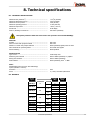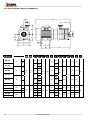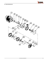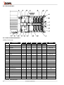
1
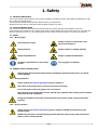
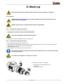
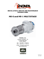
INSTALLATION, SERVICE AND MAINTENANCE
INSTRUCTIONS
MS-0 and MS-1 MULTISTAGE
INOXPA, S.A.
c/Telers, 54 Aptdo. 174
E-17820 Banyoles
Girona (Spain)
Tel. : (34) 972 - 57 52 00
Fax. : (34) 972 - 57 55 02
Email: [email protected]
www.inoxpa.com
MIMS-01_EN
ED.05.08/04
MANUFACTURER DECLARATION
According the EC directive about machines
98/37/CE, Annex II B
The manufacturer:
INOXPA, S. A.
c/ Telers, 54
17820 Banyoles (Girona) - Spain
Hereby declares, that the pumps
MULTI-STAGE TURBINE
Denomination
MS-0 / MS-1
Type
2004
Manufacturing year
Comply with the pertinent disposition, in the execution supplied by INOXPA, S.A. for
the incorporation in a machine or installation, or for the assembly with other machines
as a subunit of other higher order machine.
Harmonized norms used, particularly:
EN 292 part 1 and 2, EN 809
The machine above must not be put into service until the machinery into which it has
been incorporated have been declared in conformity with the EC Machinery Directive.
It must meet, particularly, the standards EN 294, EN 563, EN 809 y EN 953 in its
respective current editions.
Year of CE marking: CE 95
Banyoles, January 1995
EC DECLARATION OF CONFORMITY
According the EC directive about machines
98/37/CE, Annex II A
The manufacturer:
INOXPA, S. A.
c/ Telers, 54
17820 Banyoles (Girona) - Spain
Hereby declares, that the pump
MULTI-STAGE TURBINE
Denomination
MS-0 / MS-1
Type
2004
Manufacturing year
Are in conformity with the essential requirements of the Machinery Directive 98/37/CE
(latest modifications included) and according the following Council Direcitves and
harmonized norms:
- 72/23/CE Directive “low voltage”
- Norms EN 292 part 1 and 2, EN 809
Year of CE marking: CE 95
Banyoles, January 1995
1. Safety
1.1. INSTRUCTIONS MANUAL
This manual contains information about the reception, installation, operation, assembly, disassembly and maintenance of the
MS-0 / MS-1 MULTISTAGE pumps.
The information provided in this Instructions Manual is based on updated facts.
INOXPA reserves the right to modify this Instructions Manual without prior notice.
1.2. START-UP INSTRUCTIONS
This Instructions Manual contains vital and useful information for properly operating and maintaining your pump.
Read carefully these instructions before starting up the pump; become familiar with the operation and use of your pump and
follow the instructions closely. It is very important that a copy of these Instructions is kept in a set place near the plant.
1.3. SAFETY
1.3.1. Warning signs
General danger of injury
Danger of injuries caused by the rotary
parts of the equipment
Electrical hazard
Danger! Caustics or etching materials
Danger! Suspended load
Danger of equipment malfunction
Compulsory requirement to ensure safety
at work
Use of goggles is compulsory
1.4. GENERAL SAFETY INSTRUCTIONS
Read carefully this Instructions Manual before installing the pump and starting it up. If in doubt,
contact INOXPA.
1.4.1. During installation
Always observe the Technical Specification given in Chapter 8.
Never start up the pump before it has been connected to the piping.
Do not start up the pump if the pump cover is not in place.
Check that the motor specifications are the required ones, especially when working under conditions
that involve the risk of explosion.
During the installation of the pump, all the electrical work must be carried out by an authorized
operative.
1.4.2. During operation
Always observe the Technical Specification given in Chapter 8. NEVER exceed the limit of the
specified values.
NEVER touch the pump or the pipes during operation when the pump is being used to decant hot
fluids or when it is being cleaned.
1.Safety
3
The pump contains moving parts. Never introduce your fingers into the pump while the pump is in
operation.
NEVER operate the pump with the inlet and discharge valves closed.
NEVER clean the electrical motor with water. The standard protection of the motor is IP-55:
Protection against dust and spraying water.
1.4.3. During maintenance
Always observe the Technical Specification given in Chapter 8.
NEVER disassemble the pump before the pipes have been emptied. Remember that some of the fluid
will always remain in the pumpcasing (when no drainage is provided). Note that the pumped fluid
may be dangerous or very hot. Please refer to the regulations applicable in the respective country.
Do not leave detached parts on the floor.
ALWAYS disconnect the pump from the power before beginning the maintenance. Remove the fuses
and disconnect the cables from the motor terminals.
All the electrical work must be carried out by an authorized operative.
1.4.4. Compliance with the instructions
Any failure to comply with the instructions might entail risks to the operators, the environment and the equipment, and result
in the loss of the right to claim for damages.
Such non-compliance might entail the following risks:
•
Failure of important functions of the equipment / plant.
•
Failure of specific maintenance and repair procedures.
•
Threat of electrical, mechanical and chemical risks.
•
Environmental risks caused by the release of substances.
1.4.5. Warranty
Any warranty provided shall immediately and ipso jure become void, and INOXPA shall be indemnified against any product
liability claim from third parties, if:
•
the service and maintenance work was not carried out in accordance to the service instructions, or the repair work has
not been carried out by our personnel or it has been carried without our written authorization;
•
our materials have been changed without prior written authorization;
•
the parts or lubricants used are not original INOXPA parts and products;
•
the materials were used improperly or carelessly, or not in accordance to these instructions and their intended use;
•
pump parts were damaged by strong pressure for lack of a safety valve.
The General Delivery Terms already furnished to you also apply.
No change can be made to the equipment without prior discussion with the manufacturer. For your
safety, please use original spare parts and accessories.
The use of other parts will release the manufacturer from any liability.
The service terms can only be changed with prior written authorisation from INOXPA.
When in doubt, or if you would like more detailed information on specific matters (adjustment, assembly, disassembly), please
do not hesitate to contact us.
4
1.Safety
2. Index
1.
Safety
1.1. Instructions manual......................................................................................................... 3
1.2. Start-up instructions ........................................................................................................ 3
1.3. Safety............................................................................................................................. 3
1.4. General safety instructions ............................................................................................... 3
2.
Index
3.
General information
3.1. Description...................................................................................................................... 6
3.2. Operating principle .......................................................................................................... 6
3.3. Use................................................................................................................................. 6
4.
Installation
4.1. Reception of the pump .................................................................................................... 7
4.2. Handling and storage....................................................................................................... 7
4.3. Location.......................................................................................................................... 8
4.4. Pipes .............................................................................................................................. 8
4.5. Electric wiring.................................................................................................................. 8
5.
Start-up
5.1. Start-up .......................................................................................................................... 9
6.
Operating problems
7.
Maintenance
7.1. General..........................................................................................................................11
7.2. Storage..........................................................................................................................11
7.3. Cleaning ........................................................................................................................11
7.4. Disassembly / Assembly of the pump...............................................................................12
8.
Technical specifications
8.1. Technical specifications...................................................................................................17
8.2. Weights .........................................................................................................................17
8.3. Multistage MS-0 and MS-1 dimensions .............................................................................18
8.4. Multistage MS-0..............................................................................................................19
8.5. Multistage MS-1..............................................................................................................20
8.6. Multistage MS-0..............................................................................................................21
8.7. Parts list Multistage MS-0 ................................................................................................21
8.8. Multistage MS-1..............................................................................................................22
8.9. Parts list multistage MS-1................................................................................................22
2.Index
5
3. General information
3.1. DESCRIPTION
INOXPA’s MS-01 and MS-1 multistage pumps are manufactured in stamped AISI 316L stainless steel sheet.
The MS-0 and MS-1 multistage pumps are compact, closed-coupled pumps with axial suction and radial discharge and they use
health-safe connections and DIN 11851 adapters. The impellers are of closed and stamped construction. The mechanical seal is
interior and its working surfaces are made of silicon carbide, silicon carbide with EPDM gaskets in the standard version.
The motor conforms to IEC standards. IP-55 protection. Class-F isolation. Three-phase power 220-240 / 380-420 V @ 50 Hz.
On demand, motors suitable for operating in explosive environments can be provided. Depending on the environmental
conditions, the motors can be flameproof (EExd) or enhanced-safety (EExe) motors.
The design of the multistage MS-0 and MS-1 pumps makes them suitable for handling low-viscosity fluids, preferably without
solid particles.
3.2. OPERATING PRINCIPLE
The impellers, each of them housed inside its respective venturi casing, rotate in conjunction with the multistage shaft. The
coaxial venturi transfers the fluid flowing out from each impeller to the suction opening of the following stage.
Each impeller and its respective venturi casing comprise a pumping stage. These stages follow the operation principle of
centrifugal pumps.
Each stage increases the pressure of the fluid, and the successive increases are cumulative.
3.3. USE
As a general rule, standard multistage pumps are mainly used in the food-processing industry for the transfer of fluids, filters
systems, filling heat-exchanging.
Because of their design, multistage pumps are especially suitable for plants requiring high pressure at low flow, achieving
efficiency higher than single stage centrifugal pump.
3.3.1. Range of applications
The range of application for each type of pump is limited. The pump was selected for a given set of
pumping conditions when the order was placed. INOXPA shall not be liable for any damage resulting
from the incompleteness of the information provided by the purchaser (nature of the fluid, RPM,
etc.).
6
3.General information
4. Installation
4.1. RECEPTION OF THE PUMP
INOXPA cannot be held responsible for the damage sustained by the equipment during transport or
unpacking. Please visually check that the packaging is not damaged.
The pump package includes the following documents:
•
Dispatch sheets.
•
Instruction and Service Manual of the pump.
•
Instruction and Service Manual of the motor (*)
(*) when the pump is supplied with an motor by INOXPA.
Unpack the pump and check the following:
• The suction and discharge connections of the pump,
removing any rest of packaging materials.
• The pump and the motor are not damaged.
• If the equipment is not in good condition and/or any part is
missing, the carrier should report accordingly as soon as
possible.
4.1.1. Identification of the pump
Serial number
Pump plate
4.2. HANDLING AND STORAGE
Multistage pumps are often too heavy to be handled and stored manually.
Lift the pump as shown below:
4.Installation
7
4.3. LOCATION
Place the pump as close as possible to the suction tank, and if possible below the fluid level.
Place the pump so as to allow around it space enough to access the pump and the motor. (See Chapter 8 Technical
Specification for dimensions and weight).
Mount the pump on a flat, level surface.
The foundation must be rigid, horizontal, level and vibration-proof.
Install the pump so as to allow proper ventilation.
If the pump is installed outdoors, it should be covered by a roof. Its location should allow easy
access for inspection or maintenance operations.
4.4. PIPES
• As general rule, fit the suction and discharge pipes in straight sections, with the least possible number of bends and
accessories in order to reduce as much as possible any loss of load caused by friction.
• Ensure that the nozzles of the pump are properly aligned to the pipe and their diameter is similar to that of the pump
connections.
• Place the pump as close as possible to the suction tank, if possible below the fluid level, or even below the tank, so that the
manometric head of the static suction is highest.
• Place pipe supports as close as possible to the suction and discharge nozzles of the pump.
4.4.1. Cut-off valves
The pump can be isolated for maintenance purposes. To such end, cut-off valves must be fitted to the suction and discharge
nozzles of the pump.
These valves must ALWAYS be open during operation of the pump.
4.5. ELECTRIC WIRING
The connection of the electrical motors must be performed by a qualified operative.
Take all necessary precautions to prevent the failure of connections and cables.
The electrical equipment, the terminals and the components of the control systems may still bear
electrical current when powered off. Contact with them may be dangerous for operators or cause
irreversible damage to equipment.
Before handling the pump, make sure that the switchboard is not powered on.
•
•
Connect the motor following the manufacturer’s instructions.
Check the direction of rotation (see the label on the pump).
Start the pump motor briefly. Ensure the pumping direction is
the right one. If the pump operates in the wrong direction it
may cause severe damage.
ALWAYS check the direction of rotation of motor with fluid inside de pump.
For models with a seal chamber, ALWAYS ensure that the chamber is full of fluid before checking the
direction of rotation.
8
4.Installation
5. Start-up
Before starting the pump, carefully read the instructions given in Chapter 4. Installation.
5.1. START-UP
Read Chapter 8 Technical Specification carefully. INOXPA cannot be held responsible for the
improper use of the equipment.
NEVER touch the pump or the pipes when hot fluid is being pumped.
5.1.1. Checks before starting up the pump
• Fully open the cut-off valves on the suction and discharge pipes.
• If the fluid does not flow into the pump, fill the pump with fluid.
The pump must NEVER rotate without fluid inside it.
• Check that the direction of rotation of motor is the right one.
5.1.2. Checks when starting up the pump
• Check whether the pump makes strange sounds.
• Check whether the absolute inlet pressure is enough to avoid cavitation in the pump. See the curve to determine the
minimum pressure required above steam pressure (NPSHr).
• Control discharge pressure.
• Check that there are no leaks through the sealed areas.
A cut-off valve on the suction pipe must no be used to regulate flow. Cut-off valves must be fully
open during operation.
Control motor consumption to avoid power overload.
To reduce flow and motor consumption:
• Regulate flow on the discharge area of
the pump.
• Reduce motor speed.
5.Start-up
9
6. Operating problems
The following table provides solutions to problems that might arise during the operation of the pump. The pump is assumed to
have been properly installed and be suitable for the relevant application.
Please contact INOXPA if technical assistance is required.
Operating problems
Probable causes
Motor overload
The pump does not provide enough flow or pressure
No pressure on the discharge side
Uneven discharge flow / pressure
Noise and vibration
The pump gets clogged
Overheated pump
Excessive wear
The mechanical seal leaks
8, 9, 13.
1, 2, 4, 5, 7, 9, 10, 17,19.
2, 3, 6, 18,19.
1, 2, 4, 5, 6, 9.
2, 4, 5, 6, 7, 8, 9, 10, 13, 14, 15, 20, 21.
9, 10, 13, 14, 15, 20, 21.
8, 9, 10, 13, 14, 20, 21.
4, 5, 10, 14, 15, 20, 21.
11, 12, 16.
Probable causes
1
2
Wrong direction of rotation
NPSH is not high enough
3
4
5
6
7
Pump not drained
Cavitation
Air is suctioned by the pump.
Clogged suction pipe
Discharge pressure too high
8
9
10
11
12
13
Flow too high
Fluid viscosity too high
Fluid temperature too high
Mechanical seal damaged or worn out
O-rings unsuitable for the fluid
Excessive impeller expansion
14
15
16
17
18
19
20
21
Stressed pipes
Foreign matter in the fluid
The mechanical seal tension is too low
Pump speed too low
The cut-off valve on the suction side is closed
Pump too small
Solutions
Bearings are worn out
Pump and/or motor not attached to the bedplate.
Reverse the direction of rotation
Increase the available NPSH:
- Place the suction tank higher
- Place the pump lower
- Reduce steam pressure
- Increase the diameter of the suction pipe
- Shorten and simplify the suction pipe
Drain or fill
Increase suction pressure (see also 2)
Check the suction pipe and all its connections
Check the suction pipe and all its filters, if any
If necessary, reduce load losses, e.g. by increasing the diameter
of the pipe
Reduce speed
Reduce the viscosity, e.g. by heating the fluid
Reduce the temperature by cooling the fluid
Replace the seal
Fit suitable O-rings. Consult the manufacturer.
- Reduce temperature
- Change the impeller
Connect the pipes to the pump so as to avoid stress
Fit a filter to the suction pipe
Adjust according the instructions of this Manual
Increase speed
Check and open
Choose a larger pump size
Replace bearings; review the pump
Attach the pump and/or motor and check whether the pipes are
connected without stress
If the problem persists, use of the pump must cease immediately. Contact the pump’s manufacturers
or their representative.
10
6.Operating problems
7. Maintenance
7.1. GENERAL
Like any other machine, this pump requires maintenance. The instructions included in this manual cover the identification and
replacement of spare parts. These instructions are intended for the maintenance personnel and those responsible for the
supply of spare parts.
Please carefully read Chapter 8 Technical Specification.
All replaced materials must be disposed of /recycled in accordance to the applicable local
regulations.
ALWAYS disconnect the pump from the power before performing the maintenance.
7.1.1. Check the mechanical seal
Regularly check that there are no leaks in the shaft area. If there are leaks through the mechanical seal, replace it following the
instructions given under the Disassembly and Assembly section.
7.2. STORAGE
The pump must be completely emptied of fluid before storage. If possible, avoid exposing the components of the pump to
excessively humid environments.
7.3. CLEANING
The use of aggressive cleaning products, such as caustic soda and nitric acid, can cause skin burns.
Use rubber gloves during cleaning procedures.
Always use protective goggles.
If the pump is installed in a system with a CIP process, it is not necessary to disassemble the pump.
If the automatic cleaning process is not provided, proceed to disassemble the pump as indicated in the Disassembly and
Assembly section.
Cleaning solutions for CIP processes
Use only clear water (without chlorides) for mixing with the cleaning agents:
a) Alkaline solution:
1% in weight of caustic soda (NaOH) at 70ºC (150ºF)
1 Kg NaOH + 100 l. water = cleaning solution
or
2.2 l. NaOH at 33% + 100 l. water = cleaning solution
b) Acid solution:
0.5% in weight of nitric acid (HNO3) at 70ºC (150ºF)
0.7 liters HNO3 at 53% + 100 l. water = cleaning solution
Control the concentration of the cleaning solutions to avoid deterioration of the pump seals.
To remove the remaining cleaning products, ALWAYS perform a final rinse with clean water on completion of the cleaning
process.
7.Maintenance
11
7.4. DISASSEMBLY / ASSEMBLY OF THE PUMP
7.4.1. Cover, impellers and casings (MS-0)
Disassembly MS-0
Loosen and remove the blind nuts (54), nuts (54A) and washers (53), thus the cover (03) can be removed.
Pull out the gasket (80).
Remove the tie bars (29) of the lantern (04).
Remove the blind nut (45).
Pull out all the impellers (02, 02A, and 02B), casings (01), gaskets (80) and rings (30).
Remove the key (61) from the shaft (05).
Assembly MS-0/1
Insert the key (61) into the shaft (05).
Slide the impeller (02A) over the shaft (05) to the stop.
Fasten the blind nut (45).
Place the gasket (80) on the casing (01).
Mount the appropriate tie bars (29) to the lantern (04).
Mount the cover (03) to the casing (01).
Mount the washers (53) and blind nuts (54) to the tie bars (29), making sure that the assembly dimension matches the table
below. See detail.
Assembly MS-0/2
Insert the key (61) into the shaft (05).
Slide the impeller (02A) over the shaft (05) to the stop.
Place gasket (80) into the impeller casing (01A) and mount the casing (01) to the impeller casing (01A).
Mount the suction impeller (02B).
Fasten the blind nut (45).
Place the gasket (80) on the casing (01).
Mount the appropriate tie bars (29) to the lantern (04).
Mount the cover (03) to the casing (01).
Mount the washers (53) and blind nuts (54) to the tie bars (29).
12
7.Maintenance
Assembly MS-0/3, MS-0/4, MS-0/5, MS-0/6
Insert the key (61) into the shaft (05).
Slide the impeller (02A) over the shaft (05) to the stop.
Place the gasket (80) into the impeller casing (01A) and mount the casing (01) to the impeller casing (01A).
Mount the successive pumping stages following this procedure:
Mount the impeller (02)
Place the ring (30) and the gasket (80) on the impeller casing (01A).
Mount the casing (01) to the casing (01) of the preceding stage.
Mount the suction impeller (02B).
Fasten the blind nut (45).
Place the gasket (80) on the casing (01).
Mount the appropriate tie bars (29) to the lantern (04).
Mount the cover (03) to the casing (01).
Mount the washers (53) and blind nuts (54) to the tie bars (29), making sure that the assembly dimension matches the table
below. See detail.
7.Maintenance
13
7.4.2. Cover, impellers and casings MS-1
Disassembly
Loosen and remove the blind nuts (54), nuts (54A), thus the washers (53), the pump cover ring (30A) and the cover (03) can
be removed.
Pull out the gasket (80).
Remove the tie bars (29) of the lantern (04).
Remove the blind nut (45).
Pull out all the impellers (02, 02A), casings (01) and gaskets (80).
Remove the key (61) from the shaft (05).
Assembly
Insert the key (61) into the shaft (05).
Slide the impeller (02A) over the shaft (05) to the stop.
Place the gasket (80) on the impeller casing (01A).
Mount the successive pumping stages following this procedure:
Mount the casing (01) to the impeller casing (01A) or to the casing (01).
Place the ring (30) and the gasket (80) on the casing.
Fasten the blind nut (45).
Mount the tie bars (29) to the lantern (04).
Mount the cover (03) and the pump cover ring (30A) to the casing (01).
Mount the washers (53), nuts (54A) and blind nuts (54) to the tie bars (29), making sure that the assembly dimension matches
the table below. See detail.
14
7.Maintenance
7.4.3. Mechanical seal
Previously, disassemble the pump as shown in.
Disassembly
Remove the rotary part of the seal (08).
Remover the impeller casing (01A); the stationary part of the seal will come out along with it.
Remove the stationary part of the seal from the inside of the impeller casing.
Assembly
Before performing the assembly, check that the assembly dimension of the shaft (05) in respect to the lantern (04) is the right
one (see detail).
Slide the impeller casing (01A) over the shaft until it makes contact with the lantern. Try to achieve the right alignment of the
discharge hole.
Slide the stationary part of the seal (08) over the shaft until it makes contact with the impeller casing.
Slide the rotary part of the seal (08) over the shaft until it makes contact with the stationary part of the seal.
CAUTION! When mounting the new seal, plunge the parts and seals in soapy
water to facilitate sliding of both the stationary and the rotary parts.
7.Maintenance
15
7.4.4. Change of drive
Previously, disassemble the pump as shown in.
Disassembly
Remove the protections (47) by loosening the screws (50A), for models with motor size 90, 100, and 112.
Loosen and remove the screws that attach the lantern (04) to the motor (93). Hexagonal screws (52) for motor sizes 71 and
80, and Allen screws (51) for motor sizes 90, 100 and 112. Thus, the lantern (04) can be removed.
Remove the splash ring (82) from the shaft (05).
Remove the elastic pin (56) that makes the motor shaft and the pump shaft (05) rotate in conjunction.
Pull out the pump shaft (05) from the motor shaft.
Assembly
Drill a hole in the drive shaft according to the dimension shown in the figure below
Mount the pump shaft (05) to the shaft of the motor (93).
Insert the elastic pin (56) into the shaft, thus attaching the motor shaft to the pump shaft.
Slide the splash ring (82) over the shaft (05) into position.
Place the lantern (04) in position and attach it to the motor (93) using the screws. Hexagonal screws (52) for models with
motor sizes 71 and 80, and Allen screws (51) for models with motor sizes 90, 100 and 112.
Check the assembly dimension of the shaft. See the parts list detail.
Fit the protections (47) to the lantern using the screws (50A), for models with motor size 90, 100, and 112.
CAUTION! When mounting the new seal, plunge the parts and seals in soapy
water to facilitate sliding of both the stationary and the rotary parts.
16
7.Maintenance
8. Technical specifications
8.1. TECHNICAL SPECIFICATIONS
Maximum flow (2900 min-1) ....................................................
Maximum differential pressure ................................................
Maximum suction pressure .....................................................
Maximum operating pressure ..................................................
Maximum temperature ............................................................
Sound level ............................................................................
Suction / discharge connections ..............................................
21 m3/h (92 GPM)
15 bar (218 PSI)
4 bar (58 PSI)
15 bar (218 PSI)
+95ºC (+203 ºF)
60-80 dB(A)
DIN 11851 (standard)
Use special protection when the noise level in the operation area exceeds 85 dB(A).
Materials
Impeller ................................................................................
Parts in contact with pumped material .....................................
Gaskets in contact with pumped material ................................
Other materials for optional gaskets ........................................
Surface finishing ....................................................................
AISI 316L
AISI 316L
EPDM (standard) Quality FDA 177.2600
Check with the supplier
Electropolished
Mechanical seal
Type of seal ...........................................................................
Stationary parts material ........................................................
Rotary parts material ..............................................................
Seals material ........................................................................
Inside single seal
Silicon carbide (standard) or graphite
Silicon carbide (standard)
EPDM (standard), Viton® or NBR.
Motor
Standard IEC B34 motor (legs and small flange)
2 poles (2900min-1 at 50 Hz)
Protection ..............................................................................
Power ...................................................................................
IP55
3~, 50Hz, 220-240V∆/380-420VY
8.2. WEIGHTS
Pump
type
MS-0/1
Motor
Size
KW.
0.37
71
0.55
MS-0/2
0.75
MS-0/3
80
1.1
MS-0/4
1.5
MS-0/5
MS-0/6
MS-1/2
MS-1/3
MS-1/4
MS-1/5
MS-1/6
90
2.2
100
1.5
2.2
3
112
4
90
8.Technical specifications
Weight
[Kg]
Weight
[lbs]
8
9
9.5
12
13
15.5
16
20.5
21
23
24
26.5
30
38
40
41.5
17.5
20
21
26.5
29
34
35
45
46
51
53
58
66
83.5
88
91
17
8.3. MULTISTAGE MS-0 AND MS-1 DIMENSIONS
Pump type
MS-0/1
Motor
DNa
Size
KW.
DNi
0.37
71
A
B
62
327
0.55
MS-0/2
81
0.75
MS-0/3
80
1.1
40
11/2”
25
1”
MS-0/4
99
118
1.5
MS-0/5
2.2
MS-0/6
MS-1/2
MS-1/3
MS-1/4
MS-1/5
MS-1/6
18
136
90
90
406
120
80
454
265
473
90
508
117
488
143
552
169
608
195
634
58
122
8.Technical specifications
100
112
H
φI
J
K
90
110
7
112
136
125
154
140
170
140
170
160
197
190
222
125
100
150
100
278
125
320
380
74
125
252
354
L
10
284
302
90
G
231
249
2.2
4
40
424
438
112
164
212
91
25
1”
71
F
387
1.5
40
11/2”
E
182
526
3
D
345
155
100
C
150
10
172
140
168
12
91
8.4. MULTISTAGE MS-0
8.Technical specifications
19
8.5. MULTISTAGE MS-1
20
8.Technical specifications
8.6. MULTISTAGE MS-0
8.7. PARTS LIST MULTISTAGE MS-0
Quantity per pump type
Position
Description
MS-0/1 MS-0/2 MS-0/3
MS-0/4 MS-0/4
MS-0/5 MS-0/6
t. 80
t.90
Material
01
Pump casing
0
1
2
3
3
4
5
AISI 316L
01A
Impeller casing
1
1
1
1
1
1
1
AISI 316L
02
Impeller
0
0
1
2
2
3
4
AISI 316L
02A
Discharge impeller
1
1
1
1
1
1
1
AISI 316L
02B
Suction impeller
0
1
1
1
1
1
1
AISI 316L
03
Pump cover
1
1
1
1
1
1
1
AISI 316L
04
Lantern
1
1
1
1
1
1
1
GG-22
05
Shaft
1
1
1
1
1
1
1
AISI 316L
Mechanical seal
1
1
1
1
1
1
1
SiC/SiC/EPDM
29
Tie bar
4
4
4
4
4
4
4
AISI 316
45
Blind nut
1
1
1
1
1
1
1
AISI 316L
47
Protection
0
0
0
0
2
2
2
Plastic
50A
Screw
0
0
0
0
4
4
4
A2
08 *
51
Allen screw
4
4
4
4
0
0
0
8.8
52
Hexagonal screw
0
0
0
0
4
4
4
8.8
53
Spring washer
4
4
4
4
4
4
4
A2
53C
Spring washer
0
0
0
0
4
4
4
8.8
54
Blind nut
4
4
4
4
4
4
4
A2
56
Elastic pin
1
1
1
1
1
1
1
A2
61
Key
1
1
1
1
1
1
1
A2
O-ring
1
2
3
4
4
5
6
EPDM
82
Splash ring
1
1
1
1
1
1
1
EPDM
93
Motor
1
1
1
1
1
1
1
-
80 *
(*) Recommended spare parts
8.Technical specifications
21
8.8. MULTISTAGE MS-1
8.9. PARTS LIST MULTISTAGE MS-1
Quantity per pump type
Position
Description
MS-1/2
MS-1/3
MS-1/4
MS-1/5
MS-1/6
Material
01
Pump casing
1
2
3
4
5
AISI 316L
01A
Impeller casing
1
1
1
1
1
AISI 316L
02
Impeller
1
2
3
4
5
AISI 316L
02A
Discharge impeller
1
1
1
1
1
AISI 316L
03
Pump cover
1
1
1
1
1
AISI 316L
04
Lantern
1
1
1
1
1
GG-22
05
Shaft
1
1
1
1
1
AISI 316L
08 *
Mechanical seal
1
1
1
1
1
SiC/SiC/EPDM
29
Tie bar
4
4
4
4
4
AISI 316
30A
Pump cover ring
1
1
1
1
1
AISI 316
45
Blind nut
1
1
1
1
1
AISI 316L
47
Protection
2
2
2
2
2
Plastic
50A
Screw
4
4
4
4
4
A2
52
Hexagonal screw
4
4
4
4
4
8.8
53
Spring washer
4
4
4
4
4
A2
53A
Spring washer
4
4
4
4
4
8.8
54
Blind nut
4
4
4
4
4
A2
56
Elastic pin
1
1
1
1
1
A2
61
Key
1
1
1
1
1
A2
O-ring
2
3
4
5
6
EPDM
82
Splash ring
1
1
1
1
1
EPDM
93
Motor
1
1
1
1
1
-
80 *
(*) Recommended spare parts
22
8.Technical specifications
NOTES
INOXPA, S.A.
C/ Telers, 54 - PO Box: 174
Tel: (+34) 972 575 200
Email: [email protected]
17820 BANYOLES (Girona - Spain)
Fax: (+34) 972 575 502
Web: www.inoxpa.com
Gsm: (+34) 629 807 300
BARCELONA – FLUAL, S.L.
Tel: 937 297 280
Email: [email protected]
MADRID – INOXFLUID, S.L
Tel: 918 716 084
Email: [email protected]
BILBAO – STA,S.L.
Tel: 944 572 058
Email: [email protected]
VALENCIA – INOXDIN, S.L.
Tel: 963 170 101
Email: [email protected]
VALLADOLID – ALTAFLUID, S.L.
Tel: 983 403 197
Email: [email protected]
JEREZ – CORFLUID, S.L.
Tel: 956 140 193
Email: [email protected]
ZARAGOZA – FLUAL, S.L.
Tel: 976 591 942
Email: [email protected]
LA RIOJA – STA, S.L.
Tel: 941 228 622
Email: [email protected]
SEVILLA – CORFLUID, S.L.
Tel: 954 296 852
Email: [email protected]
CÓRDOBA – CORFLUID, S.L.
Tel: 957 326 542
Email: [email protected]
LA MANCHA – INOXFLUID, S.L.
Tel: 926 514 190
Email: [email protected]
INOXPA FRANCE, S.A. - AGENCE NORD
AGENCE RHÔNE-ALPES
2, Avenue Saint Pierre
59118 WAMBRECHIES (France)
Tel: 33(0)320 631000
Fax: 33(0)320 631001
Email: [email protected]
Z.l. Chapotin Nord
CHAPONNAY 69970 (France)
Tel: 33(0)472 709090
Fax: 33(0)472 709091
Email: [email protected]
AGENCE SUD EST
Route d’Olonzac
11200 HOMPS (France)
Tel: 33(0)468 278680
Fax: 33(0)468 278681
Email: [email protected]
AGENCE OUEST
ZA des Roitelières
44330 LE PALLET (France)
Tel: 33(0)228 010172
Fax: 33(0)228 010173
Email: [email protected]
INOXPA SKANDINAVIEN A/S
H∅egh Guldbergsgade 27
HORSENS DK-8700 (Denmark)
Tel: (45) 76 28 69 00
Fax: (45) 76 28 69 09
Email: [email protected]
INOXPA ITALIA S.R.L.
Via Kennedy, 13
RODANO (MILAN) 20090 (Italia)
Tel: 39(0)02 95327292
Fax: 39(0)02 95327168
Email: [email protected]
INOXPA SWEDEN
Stationsvägen 2
430 63 HINDÅS
Tel. +46 (0) 301 21122
Fax +46 (0) 301 21125
Email: [email protected]
INOXPA (UK) LTD
Unit 2, Ashfield Close, Whitehall
Industrial Estate LEEDS
WEST YORKSHIRE, LS12 5JB
(United Kingdom)
Tel: 44(0) 1132 636367
Fax: 44(0) 1132 636384
Email: [email protected]
INOXPA SOUTH AFRICA (PTY) LTD
48 Marconi Road Montague Gardens
CAPE TOWN 7441
(Republic of South Africa)
Tel: 27(0)21 5514533 / 1571
Fax: 27(0)21 5514534
Email: [email protected]
S.T.A. PORTUGUESA LDA.
Zona Industrial - Lugar do Guardal
ALGERIZ. 3730-266 VALE DE CAMBRA
(Portugal)
Tel: 351 256 472722
Fax: 351 256 425697
Email: [email protected]
INOXPA POLAND sp z o.o.
Ul. Arkonska, 54
80-392 Gdansk
(Poland)
Tel. +48 58 511 00 05
Fax +48 58 556 72 51
Email: [email protected]
INOXPA USA, Inc
3715 Santa Rosa Avenue Suite A4
Santa Rosa, CA95409
(California)
Tel. 1.707.585.3900
Fax 1.707.585.3908
Email: [email protected]
INOXPA DEUTSCHLAND
Email: [email protected]
.
INOXPA products are available from our branch offices and through a network of independent distributors covering more than 50 countries
around the World.
For more information, visit our Web site:
www.inoxpa.com
This information is given for guidance only. We reserve the right to change any materials or characteristics without prior notice.