1
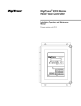
11.03/
Operating Manual
BR 70.3011/1
Compact microprocessor controller
DigiTrace TCONTROL-CONT-02
E
!
!
Please note that we can not be held liable for any damages caused by ESD (electrostatic
discharges).
When returning chassis, assemblies or components, the rules of EN 100 015 “Protection of
electrostatically endangered components” have to be observed. Use only the appropriate
ESD packaging material for transport.
All necessary settings are described in this Operating Manual. If any difficulties should still
arise during start-up, you are asked not to carry out any manipulations on the unit which are
not permitted. You could endanger your rights under the warranty. Please contact the nearest office or the main factory.
Please read this Manual carefully before starting up the instrument. Keep this Manual in a
place which is at all times accessible to all users. Please assist us to improve this Manual
where necessary. Your suggestions will be most welcome.
26, 41
0
80
0
0
Al 2
Pb 1
Pb 2a
22, 41
350
20.0
20.0
0
rt
Cy 1
Cy 21
db
24, 41
24, 41
16, 41
100
-100
0.6
0
Y1
Y2
dF
rASd
31, 41
23, 41
0
23, 41
HYS 21 1.0
Y0
23, 41
HYS 1 2
1.0
23, 41
22, 41
22, 41
22, 41
22, 41
80
>2sec dt
P
26, 41
2
Al 1
22, 41
Page
Parameter level
Default Settings
SCL
1
0
0
850
600
-200
40
250
-50
0104
0013
2004
8714
0000
26, 40
17, 40
18, 40
18, 40
17, 40
17, 40
24, 28, 31,
39
26, 27, 29,
38
16, 20, 27,
37
Page
a. This parameter appears only if a double
setpoint controller has been configured
as controller type.
k= factory setting
HySt
OFFS
SPH
>2sec SCH
SPL
P
C114
C113
C112
C111
Configuration level
5
4
1
2
3
Description . . . . . . . . . . . . . . . . . . . . . . . . . . . . . . . . . . . . . . . . . . . . . . . . . . . . . . . . . . . . . . 4
TCONTROL-CONT-02 Factory Settings . . . . . . . . . . . . . . . . . . . . . . . . . . . . . . . . . . . . . . . . 5
Installation . . . . . . . . . . . . . . . . . . . . . . . . . . . . . . . . . . . . . . . . . . . . . . . . . . . . . . . . . . . . . . . 6
3.1 Dimensions . . . . . . . . . . . . . . . . . . . . . . . . . . . . . . . . . . . . . . . . . . . . . . . . . . . . . . . . . . 6
3.2 Fitting in position and removing the controller chassis . . . . . . . . . . . . . . . . . . . . . . . . . 7
3.3 Cleaning the front panel . . . . . . . . . . . . . . . . . . . . . . . . . . . . . . . . . . . . . . . . . . . . . . . . . 7
Electrical connection . . . . . . . . . . . . . . . . . . . . . . . . . . . . . . . . . . . . . . . . . . . . . . . . . . . . . . 8
4.1 Notes on installation . . . . . . . . . . . . . . . . . . . . . . . . . . . . . . . . . . . . . . . . . . . . . . . . . . . 8
4.2 Connection diagram . . . . . . . . . . . . . . . . . . . . . . . . . . . . . . . . . . . . . . . . . . . . . . . . . . 10
Operation . . . . . . . . . . . . . . . . . . . . . . . . . . . . . . . . . . . . . . . . . . . . . . . . . . . . . . . . . . . . . . 11
5.1 Displays and keys . . . . . . . . . . . . . . . . . . . . . . . . . . . . . . . . . . . . . . . . . . . . . . . . . . . . 11
5.2 Principle of operation . . . . . . . . . . . . . . . . . . . . . . . . . . . . . . . . . . . . . . . . . . . . . . . . . . 12
5.3 Entering setpoints and parameters . . . . . . . . . . . . . . . . . . . . . . . . . . . . . . . . . . . . . . . 14
5.4 Entering the configuration codes . . . . . . . . . . . . . . . . . . . . . . . . . . . . . . . . . . . . . . . . . 14
Contents
Contents
7
6
Configuration . . . . . . . . . . . . . . . . . . . . . . . . . . . . . . . . . . . . . . . . . . . . . . . . . . . . . . . . . . . 15
6.1 Process value input . . . . . . . . . . . . . . . . . . . . . . . . . . . . . . . . . . . . . . . . . . . . . . . . . . . 16
6.2 Setpoint limits . . . . . . . . . . . . . . . . . . . . . . . . . . . . . . . . . . . . . . . . . . . . . . . . . . . . . . . 18
6.3 Logic inputs . . . . . . . . . . . . . . . . . . . . . . . . . . . . . . . . . . . . . . . . . . . . . . . . . . . . . . . . . 19
6.4 Controller . . . . . . . . . . . . . . . . . . . . . . . . . . . . . . . . . . . . . . . . . . . . . . . . . . . . . . . . . . . 21
6.5 Limit comparators . . . . . . . . . . . . . . . . . . . . . . . . . . . . . . . . . . . . . . . . . . . . . . . . . . . . 25
6.6 Outputs . . . . . . . . . . . . . . . . . . . . . . . . . . . . . . . . . . . . . . . . . . . . . . . . . . . . . . . . . . . . 27
6.7 Display . . . . . . . . . . . . . . . . . . . . . . . . . . . . . . . . . . . . . . . . . . . . . . . . . . . . . . . . . . . . . 29
6.8 Ramp function . . . . . . . . . . . . . . . . . . . . . . . . . . . . . . . . . . . . . . . . . . . . . . . . . . . . . . . 30
6.9 Programme controller . . . . . . . . . . . . . . . . . . . . . . . . . . . . . . . . . . . . . . . . . . . . . . . . . 32
6.10 Self-optimisation . . . . . . . . . . . . . . . . . . . . . . . . . . . . . . . . . . . . . . . . . . . . . . . . . . . . . 35
Appendix . . . . . . . . . . . . . . . . . . . . . . . . . . . . . . . . . . . . . . . . . . . . . . . . . . . . . . . . . . . . . . . 37
7.1 Configuration code and parameter tables . . . . . . . . . . . . . . . . . . . . . . . . . . . . . . . . . . 37
7.2 Alarm messages . . . . . . . . . . . . . . . . . . . . . . . . . . . . . . . . . . . . . . . . . . . . . . . . . . . . . 42
7.3 Technical data . . . . . . . . . . . . . . . . . . . . . . . . . . . . . . . . . . . . . . . . . . . . . . . . . . . . . . . 43
Contents
Description
■ 2 parameter sets with
parameter set switching
■ 2 setpoints with
setpoint switching
■ 1 limit comparator
■ Programmable input filter
■ Programme function
■ Ramp function
■ Self-optimisation
■ Programmable single / double
setpoint controller or
proportional controller with
PID structure.
1
or
or
Logic input 1
for floating contact
Logic input 2
for floating contact
110-240 V AC 48-63 Hz
Process value input
for Pt 100, Pt 1000,
thermocouples or
standard signals
Output 5
- logic 5V
Output 4
- logic 5V
Output 3
- relay
Output 2
- relay
Output 1
- relay
4
1 Description
Control Mode:
Input:
Output Relay K1
See Section 6.5
lk1 — lk8
Delivery package:
- controller
- 1 seal
- 1 mounting frame
- Operating Manual BR 70.3011
Alarms
Limit Comparators
TCONTROL-CONT-02 Factory Settings
O function for process heating
Pt 100 (3 wire)
Control Output
(setpoint 5°C, hysteresis 2)
Relay K2
Alarm (Limit Comparator)
(set as low temperatur alarm
2° C, hysteresis 0)
Alarm
(limit comparator)
Relay K3
(set as high temperature
alarm 80°C, hysteresis 0)
Supply Voltage
110 - 240 V + 10/-15 %
Control Funktion
See48
Section
AC
- 63 Hz6.4
Single Control
O Funktion on/off
Software
Selectable Settings
Single Control
S Funktion on/off
PID Control
Control
ProcessFunktion
value Input
See
SeeSection
Section6.1
6.4
Linearised
transducers
Pt 100Control
Single
Funktion
4O—
20 mA on/off
Pt 1000
Single
S Funktion on/off
Fe-ConControl
J
PID
Control
Cu-Con
U
Fe-Con Lvalue Input
Process
See Section 6.1
NiCr-Ni K
Pt 100
Linearised transducers
Pt 1000
4 - 20mA
Fe-Con J
Cu-Con U
Fe-Con L
NiCr-Ni K
2
5
2 TCONTROL-CONT-02 Factory Settings
Installation
Dimensions
3
3.1
6
3 Installation
Cleaning the front panel
The front panel can be cleaned with the usual wash and rinse agents and cleaners. It has a limited
degree of resistance to organic solvents (e. g. petrol, benzene, P1, xylene and similar). Do not use
any high-pressure cleaners.
3.3
h Press together the knurled areas (top and
bottom) on the front panel and pull out the
controller chassis.
h From the back of the panel, push the
mounting frame onto the instrument
housing and press it against the back of
the panel, compressing the springs, until
the latches snap into the notches provided
and it is securely fixed in position.
h Insert the controller from the front into the
panel cut-out.
Seal
Fitting in position and removing the controller chassis
h Fit the seal provided onto the instrument
housing
3.2
7
3 Installation
Notes on installation
4.1
- Run input, output and supply lines separately and not parallel to each other.
- Electromagnetic compatibility conforms to the standards and regulations listed under
Technical Data.
- A current limiting resistor interrupts the supply circuit in case of a short-circuit. The external
fuse of the supply should not be rated above 1 A (slow). The load circuit must be fused for the
maximum relay current in order to prevent welding of the output relay contacts in case of an
external short-circuit.
- If contact with live parts is possible when working on the instrument, it has to be isolated on
both poles from the supply.
- The electrical connection must only be carried out by properly qualified personnel.
- The choice of cable, the installation and the electrical connection must conform to the requirements of VDE 0100 “Regulations on the Installation of Power Circuits with nominal
voltages below 1000 V” or the appropriate local regulations.
Electrical connection
4
8
4 Electrical connection
- Apart from faulty installation, there is a possibility of interference or damage to controlled
processes due to incorrect settings on the controller (setpoint, data of parameter and
configuration levels, internal adjustments). Safety devices independent of the controller, such
as overpressure valves or temperature limiters /monitors, should always be provided and
should be capable of adjustment only by specialist personnel. Please refer to the appropriate
safety regulations in this connection. Since auto-tuning (self-optimisation) can not be expected to handle all possible control loops there is a theoretical possibility of unstable parameter
settings. The resulting process value should therefore be monitored for its stability.
- The instrument is not suitable for installation in hazardous areas.
- Do not connect any additional loads to the supply terminal of the instrument.
- Sensor and interface lines should be arranged as twisted and screened cables.
Do not run them close to current-carrying components or cables.
9
4 Electrical connection
Connection diagram
The electrical connection must
only be made by properly
qualified personnel.
4.2
V
Logic input 1+2/
Output 4+5
Process
value input
Alarm output
(K3, high temp.)
Control ouput
(K1)
Alarm output
(K2, low temp.)
AC 110-240V
Supply
10
4 Electrical connection
Operation
Displays and keys
5
5.1
Process value display
red, 10 mm, 4 digits
Setpoint display
green, 7 mm, 4 digits
PGM key
to select the parameters
Decrement key
to alter values
Increment key
to alter values
EXIT key
to quit the levels
LED for ramp / programme function
lights up when configured; green
LED for status indication
for outputs 1 to 3; yellow
(1)
(2)
(3)
(4)
(5)
(6)
(7)
(8)
11
5 Operation
Principle of operation
Operating level
Here the setpoints SP1 and SP2 are input and
the profile segments of the programme function
are programmed (if the programme function is
configured).
v Section 5.3
Standard display
The displays show the process value and the active setpoint or the programme / ramp setpoint.
The active setpoint can be changed here.
h Return to standard display with X
h Change to the next parameter with P
h Change to the next level with P
(Press key for at least 2 sec!)
Generally, the following applies:
5.2
12
5 Operation
Time-out
If no operation occurs, the controller returns automatically to standard display after approx.
30 sec.
Configuration level
The basic functions of the controller are set here.
Settings can only be made after leaving the
parameter level via the y.0 parameter.
v Section 6.4
Parameter level
The limit values of the limit comparators and the
controller parameters are programmed here.
The instrument has two parameter sets. Display
switching of the parameter sets is via parameter
Pb.1.
13
5 Operation
Entering setpoints and parameters
or
abort the input with X
Entering the configuration codes
h Select the digit with D (digit flashes!)
h Alter the value with I
h Confirm the code with P
5.4
v Section 6.2 (setpoint limits)
The value alters only within the permitted range of values.
The setpoint (parameter) is accepted automatically after approx. 2 sec; display flashes briefly
h Decrease the setpoint (parameter) with D
h Increase the setpoint (parameter) with I
Example: Altering the setpoint
in standard display
Parameters and setpoints are input and altered by continually altering the value. The change
speeds up the longer the key is held down.
5.3
14
5 Operation
Configuration
H
v Section 7.1
For the experienced user, the parameters and configuration codes are summarised in
the tables which are provided in the Appendix.
Presentation
The configuration codes have 4 positions. For functionally relevant positions, the kind of function
and its selection possibility is described in the appropriate column. Positions which are not relevant for the function are marked with an “X” in the column.
h Enter the parameters and configuration codes into the instrument
h Enter the parameter values and the configuration codes in the table provided for this
purpose on the back cover. The parameters and configuration codes are listed in the
order of their appearance.
h Familiarise yourself with the controller functions
The parameter and the configuration codes are listed in the sequence in which they appear within
the level structure. The following procedure is however recommended:
The following sections describe the functions of the instrument with their relevant parameters and
settings.
6
15
6 Configuration
Process value input
k= factory setting X = position functionally not relevant
C111 Transducer
Pt 100
Pt 1000
Fe-Con L
NiCr-Ni K
Pt10Rh-Pt S
Pt13Rh-Pt R
Pt30Rh-Pt B
Cu-Con U
NiCrSi-NiSi N
Fe-Con J
Standard signal 0 — 20 mA
Standard signal 4 — 20 mA
Filter time constant to adapt
the digital input filter (0 sec = filter off)
0.6 sec
dF
0.0—100.0 sec
factory-set Notes
Parameter Value range
The process variable is fed into the controller via the process value input.
6.1
0
1
2
3
4
5
6
7
8
9
A
b
X X X
16
6 Configuration
0
-1999 to +9999 digit1
OFFS
Process value correction (offset)
The offset can be used to correct the measured value by
a certain amount up or down.
Examples:
Measured value
Offset
Displayed value
294.7
+ 0.3
295.0
295.3
– 0.3
295.0
SCL and SCH are simultaneously the calibration
for the process value output
v Section 6.6
Start /end of value range for standard signals
Example: 0—20 mA→20 — 200 °C:
SCL = 20 / SCH = 200
On a display with one or two decimal places the value range and the factory setting
change accordingly (e. g. 1 decimal place → value range: -199.9 to +999.9).
250
-1999 to +9999 digit1
SCH
1.
-50
-1999 to +9999 digit1
factory-set Notes
SCL
Parameter Value range
17
6 Configuration
Setpoint limits
Setpoint limits
Setpoint inputs below or above these limits are not
accepted.
The value of SPL / SPH flashes on the display.
Display start /end with external setpoint input.
Low/high setpoint limit for SP1 and SP2.
Example: 4 — 20 mA → 0 — 250 °C:
SPL = 0, SPH = 250
On displays with one or two decimal places the value range and the factory setting
change accordingly (e. g. 1 decimal place → value range: -199.9 to +999.9).
600
-1999 to +9999 digit1
SPH
1.
-40
-1999 to +9999 digit1
factory-set Notes
SPL
Parameter Value range
6.2
18
6 Configuration
Logic inputs
No operation by keys
No access to parameter and
configuration level
No start of self-optimisation
Programme /ramp stopped
Programme /ramp (re)started
Setpoint SP2 is activated.
Parameter set 2 is activated.
(„ Pb.1)
Limit comparators are activated.
Operation is possible by keys
Access possible to parameter
and configuration level.
Start of self-optimisation is possible.
Programme /ramp running
(when configured!)
–
Setpoint SP1 is activated.
Parameter set 1 is activated.
(, Pb.1)
Limit comparators are off.
Key inhibit
Level inhibit
Programme/
ramp stop
Programme/
ramp start
Setpoint switching
Parameter set
switching
Enabling the
limit comparators
Various operating functions can be activated via the two logic inputs.
6.3
19
6 Configuration
H
Different functions can be combined.
k= factory setting X = position functionally not relevant
C111 Logic inputs 1 (BE1) and 2 (BE2)
no function
Key inhibit
Level inhibit
Programme /ramp stop
Programme /ramp start
Setpoint switching
Parameter set switching
Enabling limit comparators
X X BE1 BE2
0
0
1
1
2
2
3
3
4
4
5
5
6
6
7
7
20
6 Configuration
Controller
The parameter set which is displayed is shown by
lit-up segments on parameter Pb.1.
h Change between the display of the parameter sets with
P , when parameter Pb.1 is displayed
(hold key down for at least 2 sec!).
The controller has two parameter sets; a logic input can be
used to switch between them.
Both parameter sets can be displayed for setting the
parameters.
Selecting the parameter set
Controller functions
1 segment
2 segments
The controller type is set here, and the controller is adjusted to the process.
6.4
= parameter set 1
= parameter set 2
21
6 Configuration
0—9999 sec
0—9999 sec
0.5—999.9 sec
0.5—999.9 sec
dt
rt
Cy 1
Cy 2
1.
0
0—9999 digit1
Pb 2
Duration of switching cycle 1 (controller output 1)
Duration of switching cycle 2 (controller output 2)
Duration of switching cycle on switching outputs.
The cycle time should be selected so that the energy
supply to the process is virtually continuous while the
switching elements are not subject to excessive wear.
Reset time
Influences the I action of the controller.
If rt=0, the controller has no I action.
Derivative time
Influences the D action of the controller.
If dt=0, the controller has no D action.
Proportional band 1 (controller output 1)
Proportional band 2 (controller output 2)
Influences the P action of the controller
If Pb = 0, the controller structure is ineffective.
On the display with one or two decimal places the value range and the factory setting
change accordingly (e. g. 1 decimal place → value range: -199.9 to +999.9).
20.0 sec
20.0 sec
350 sec
80 sec
0
0—9999 digit1
factory-set Notes
Pb 1
Parameter Value range
Controller structure
The controller structure is defined through parameters Pb, dt and rt.
Example: PI → Pb≠0, dt=0, rt≠0
22
6 Configuration
2
1.0
1.0
0 — 9999 digit1
0 — 9999 digit1
-100 — 100 %
HYS 1
HYS 2
Y0
0%
0.0
0 — 1000 digit1
Working point
Output at x=w
Differential 1 (controller output 1)
Differential 2 (controller output 2)
For controllers with Pb=0
Contact spacing
For switching double-setpoint controllers
factory-set Notes
db
Parameter Value range
23
6 Configuration
-100 to +100 %
Y2
H
1.
On the display with one or two decimal places the value range and the factory setting
change accordingly (e. g. 1 decimal place → value range: -199.9 to +999.9).
k= factory setting X = position functionally not relevant
0
1
2
3
4
X X X
On controllers without controller structure
(Pb = 0) it is necessary that Y1 = 100% and
Y2 = -100%
C113 Controller type
Single-setpoint controller O function
Single-setpoint controller S function
Double-setpoint controller
Proportional controller with falling characteristic (indirect action)
Proportional controller with rising characteristic (direct action)
-100 %
100 %
0—100 %
Y1
Maximum /minimum output
Example: proportional controller with falling
characteristic (indirect action)
factory-set Notes
Parameter Value range
24
6 Configuration
Limit comparators
lk2
lk5
lk8
lk1
lk4
lk7
Functions of the limit comparators
lk1— lk6: Monitoring referred to
the setpoint
lk7 / lk8: Monitoring referred to
a fixed value AL.
lk6
lk3
The measurements of the two inputs can be monitored with reference to the setpoint or a fixed
value using two limit comparators.
6.5
25
6 Configuration
80
-1999 to +9999 digit1
AL 2
1.
-1999 to +9999 digit1
1
LK1 LK2 X X
0
00
1
1
2
2
2
3
3
4
4
5
5
6
6
7
77
8
8
Switching differential of the limit comparators
factory-set Notes
X = position functionally not relevant
Limit limit comparator 2
Limit limit comparator 1
In the display with one or two decimal places the value range and the factory setting
change accordingly (e. g. 1 decimal place → value range: -199.9 to +999.9).
HySt
Parameter Value range
k= factory setting
C112 Limit comparator 1 (LK1) and 2 (LK2)
no function
lk 1 (process value input)
lk 2 (process value input)
lk 3 (process value input)
lk 4 (process value input)
lk 5 (process value input)
lk 6 (process value input)
lk 7 (process value input)
lk 8 (process value input)
2
-1999 to +9999 digit1
factory-set Notes
AL 1
Parameter Value range
26
6 Configuration
Outputs
k= factory setting X = position functionally not relevant
C112 Output signal on overrange
Output 0 %, limit comparators OFF
Output 100 %, limit comparators OFF
Output -100 %, limit comparators OFF
Output 0 %, limit comparators ON
Output 100 %, limit comparators ON
Output -100 %, limit comparators ON
k= factory setting X = position functionally not relevant
C111 Output 4 (A4) and 5 (A5)
no function
Controller output 1
Controller output 2
Limit comparator output 1
Limit comparator output 2
Programme end
The five outputs can be freely assigned to the functions.
6.6
X X X
0
1
2
3
4
5
X X A4 A5
0
0
8
8
9
9
A A
b b
C C
27
6 Configuration
X = position functionally not relevant
= factory setting
X = position functionnally not relevant
no function
Controller output 1 (function: 0 - 20mA/0 - 10V/switching)
Controller output 2 (function: 0 - 20mA/0 - 10 V/switching)
Limit comparator output 1 (function: switching)
Limit comparator output 2 (function: switching)
Programme end (funciton: switching)
Controller output 1 (function: 4 - 20 mA/2 - 10V)
Controller output 2 (function: 4 - 20 mA/2 - 10V)
Process value output (function: 0 - 20 mA/0 - 10V)
Process value output (function: 4 - 20 mA/2 - 10V)
C114 Output 3 (K3)
k= factory setting
C113 Output 1 (K1; relay) and 2 (K2; relay)
no function
Controller output 1
Controller output 2
Limit comparator output 1
Limit comparator output 2
Programme end
X X X
X X K1
0
1
2
3
4
5
0
1
2
3
44
5
6
7
8
9
K3
K2
0
1
2
3
4
5
28
6 Configuration
Display
h Display the software version and unit of the process value
with P + I (hold keys down!)
Displaying the unit and software version
k= factory setting X = position functionally not relevant
C112 Decimal places /unit
no decimal place, degree Celsius
one decimal place, degree Celsius
two decimal places, degree Celsius
no decimal place, degree Fahrenheit
one decimal place, degree Fahrenheit
two decimal places, degree Fahrenheit
X X
0
1
2
3
4
5
X
The number of the decimal places when displaying process value and setpoint in the standard
display is defined here. In addition, the unit of the process value is determined.
6.7
29
6 Configuration
Ramp function
Action on power failure
When the supply is restored, the controller accepts the current process value as ramp setpoint
and continues the ramp function with the set parameters.
Action on sensor break
On sensor break the ramp function is interrupted. The outputs act as for overrange or underrange (can be configured). When the fault has been rectified,
the controller accepts the current process value as ramp setpoint and continues the ramp function.
A rising or falling ramp function is possible. When the power
is switched on, the ramp function starts with the current process value and the setpoint runs according to the selected
gradient until the ramp end point SP is reached. The ramp
end point is entered at the setpoint input (SP1, SP2). When
the ramp end point is reached, then the ramp setpoint is
equal to SP.
6.8
30
6 Configuration
k= factory setting X = position functionally not relevant
C113 Ramp function
Ramp function off
Ramp function (time base: minutes)
Ramp function (time base: hours)
X
1. In the display with one or two decimal places, the value range changes to 0.0 — 99.9 digit/h (digit/min.)
ramp gradient
0
rASd
0 —999 digit /h
or digit /min1
factory-set Notes
Parameter Value range
h Re-start the ramp with D + I or via the logic input
Re-starting the ramp
0
5
6
X X
Ramp stop
Activating the ramp stop via a logic input holds the ramp function. The setpoint display flashes.
After the ramp stop has been de-activated, the ramp function continues with the ramp setpoint
at the time of the ramp stop.
31
6 Configuration
Programme controller
It is possible to implement a setpoint programme with up to 4 profile segments. The segment setpoints (SP00 — SP03) and the segment times (t00 — t03) are set at the operating level. The time
base can be configured in seconds or minutes (max. segment time 9999 min.).
6.9
32
6 Configuration
Re-starting the programme
h Re-start the programme with D + I or via the logic input
Programme stop
The programme is held by activating the programme stop via a logic input. The setpoint display
flashes. After the programme stop has been de-activated, the programme continues with the setpoint at the time of the programme stop.
Action on power failure
When the supply is restored, the programme starts at the process value.
Action on sensor break
On sensor break the programme is interrupted. The outputs act as for overrange or underrange
(can be configured). When the fault has been rectified, the programme continues with the process
value.
v Section 6.6 “Outputs”
The programme starts at the process value, i. e. the profile is searched to find a setpoint which
corresponds to the process value at the instant of start or power-on. ((1), (2), (3)). The profile then
continues from this point. If the process value is outside the profile, a start is made at the first
profile segment and the segment setpoint is then approached with the gradient of the first segment (positive or negative). The programme can either be run through once or repeated cyclically.
In addition, a programme end signal can be output and the programme can be held.
33
6 Configuration
k= factory setting X = position functionally not relevant
C113 Programme function
Programme controller off
Programme controller (timebase: seconds)
Programme controller (timebase: seconds; cyclic)
Programme controller (timebase: minutes)
Programme controller (timebase: minutes; cyclic)
X
0
1
2
3
4
X X
34
6 Configuration
Self-optimisation
With a small deviation between setpoint and process value,
e.g. when the control loop has stabilised, a forced oscillation
about the setpoint is produced.
If there is a large deviation between process value and setpoint when SO is activated, a switching level is determined
about which the process variable performs a forced oscillation during the SO procedure. The switching level is chosen
so that the process value does not exceed the setpoint, if
possible.
The following controller parameters are defined: rt, dt, Pb1, Pb2, Cy1, Cy2, dF
Self-optimisation determines the controller parameters for PID or PI controllers.
6.10
35
6 Configuration
H
Starting SO is not possible with active level inhibit.
The active parameter set is optimised.
With active ramp /programme function, the ramp /programme sequence is stopped
during self-optimisation.
h Store the parameters with X
(Hold down key for at least 2 sec!)
If "tune" does not flash any longer, self-optimisation is terminated and the controller functions with the parameters which
have been established.
h Abort with X
(while self-optimisation is running)
h Start SO with X
(hold down key for at least 2 sec !)
Starting self-optimisation
36
6 Configuration
Appendix
0 0 0 0
k= factory-set
Process value input
Pt 100
Pt 1000
Fe-Con
L
NiCr-Ni
K
Pt10Rh-Pt S
Pt13Rh-Pt R
Pt30Rh-Pt B
Cu-Con
U
NiCrSi-NiSi N
Fe-Con
J
0 — 20 mA
4 — 20 mA
0
1
2
3
4
5
6
7
8
9
A
b
A4
8
9
A
b
C
Output 4 (A4) and 5 (A5)
Controller output 1
Controller output 2
Limit comparator output 1
Limit comparator output 2
Programme end
A5
8
9
A
b
C
BE1 BE2
0
0
1
1
2
2
3
3
4
4
5
5
6
6
7
7
Logic input 1 (BE1) and 2 (BE2)
no function
Key inhibit
Level inhibit
Programme/ramp stop
Programme/ramp start
Setpoint switching
Parameter set switching
Enabling the limit comparators
7.1
Configuration code and parameter tables
C111
7
37
7 Appendix
k= factory-set
Limit comparator 1 (LK1) LK1 LK2
and 2 (LK2)
no function
0
0
lk 1 (process value input)
1
1
2
lk 2 (process value input)
2
lk 3 (process value input)
3
3
lk 4 (process value input)
4
4
lk 5 (process value input)
5
5
lk 6 (process value input)
6
6
7
lk 7 (process value input)
7
8
lk 8 (process value input)
8
C112
Decimal places/
unit
XXXX / °C
XXX.X / °C
XX.XX / °C
XXXX / °F
XXX.X / °F
XX.XX / °F
28 07 01 44
0
1
2
3
4
5
Output 0 %, LK1+2 OFF
Output 100 %, LK1+2 OFF
Output -100 %, LK1+2 OFF
Output 0 %, LK1+2 ON
Output 100 %, LK1+2 ON
Output -100 %, LK1+2 ON
Output signal on overrange
0
1
2
3
4
5
38
7 Appendix
k= factory-set
Controller type
1-setpt. controller O function
1-setpt. controller S function
2-setpoint controller
Proportional controller
with falling characteristic
Proportional controller
with rising characteristic
C113
4
0
1
2
3
Ramp function
Ramp function
time base: minutes
Ramp function
time base: hours
Programme function
Programme controller/
ramp function off
Programme controller
time base: seconds
Programme controller
time base: seconds; cyclic
Programme controller
time base: minutes
Programme controller
time base: minutes; cyclic
0 0 1 3
6
5
4
3
2
1
0
Output 1 (K1; relay)
and 2 (K2; relay)
no function
Controller output 1
Controller output 2
Limit comparator output 1
Limit comparator output 2
Programme end
0
1
2
3
4
5
0
1
2
3
4
5
K1 K2
39
7 Appendix
!
0 0
0 1
.
.
9 9
= factory-set
9600 baud, no parity
9600 baud, odd parity
9600 baud, even parity
4800 baud, no parity
4800 baud, odd parity
4800 baud, even parity
Schnittstellenparameter
E
!
Geräteadresse
Address 0
Address 1
.
.
Address 99
C114
0
1
2
3
4
5
0
1
4
Ausgang 3 (K3; Relais)
no function
Controller output (0...20mA/0...10V/switching)
Controller output (0...20mA/0...10V/switching)
Limit comparator output 1 (switching)
Limit comparator output 2 (switching)
Programme end (switching)
Controller output (4...20mA/2...10V)
Controller output (4...20mA/2...10V)
Process value input (0...20mA/0...10V)
Process value input (4...20mA/2...10V)
0
K3
00
1
2
3
4
5
6
7
8
9
40
-40
600
0
1
-1999 to +9999 digit1
-1999 to +9999 digit1
-1999 to +9999 digit1
-1999 to +9999 digit1
SPL
SPH
OFFS
HySt
Switching differential of limit comparators
Process value correction (offset)
Display end with external setpoint input
Display start with external setpoint input
End value of value range for standard signals
Start value of value range for standard signals
On displays with one or two decimal places the value range and the factory setting
change accordingly (e. g. 1 decimal place → value range: -199.9 to +999.9).
250
-1999 to +9999 digit1
SCH
1.
-50
-1999 to +9999 digit1
factory-set Notes
SCL
Parameter Value range
The parameters of the configuration level
41
40
7 Appendix
0
0
20.0 s
0.0
1.0
1.0
0.6 s
0
0—9999 digit1
0—9999 digit1
0— 9999 sec
0— 9999 sec
0.5— 999.9 sec
0.5— 999.9 sec
0—1000 digit 1
0— 9999 digit 1
0— 9999 digit 1
-100— 100 %
0— 100 %
-100 to +100 %
0.0— 100.0 sec
0 — 999 digit 1
Pb 1
Pb 2
dt
rt
Cy 1
Cy 2
db
HYS 1
HYS 2
Y0
Y1
Y2
dF
raSd
1.
80
-1999 to +9999 digit1
AL 2
Ramp gradient
Filter time constant for adaptation
Output limitation: minimum output
Output limitation: maximum output
Working point
Switching differential 2 (controller output 2)
Switching differential 1 (controller output 1)
Contact spacing
Switching cycle time 2 (controller output 2)
Switching cycle time 1 (controller output 1)
Reset time
Derivative time
Proportional band 2 (controller output 2)
Proportional band 1 (controller output 1)
Limit for limit comparator 2
Limit for limit comparator 1
On displays with one or two decimal places the value range and the factory setting change accordingly
(e. g. 1 decimal place → value range: -199.9 to +999.9)
-100 %
100 %
0%
20.0 s
350 s
80 s
2
-1999 to +9999 digit1
factory-set Notes
AL 1
Parameter Value range
Parameter level
42
41
7 Appendix
H
Display
7.2
The following events come under the heading over /underrange:
- Sensor break /short-circuit
- Measurement is outside the control range of the connected sensor
- Display overflow
The setpoint display
flashes “1999”.
The process value display
indicates the process value.
Over /underrange of the external setpoint.
Limit comparators referred to the input for
the external setpoint act according to the
configuration of the outputs.
Over /underrange of the process value.
Controller and limit comparators referred to
the process value input act in accordance
with the configuration of the outputs.
The process value display
flashes “1999”.
The setpoint display
indicates the active setpoint
Cause/response
Description
Alarm messages
43
42
7 Appendix
Technical data
Control range
-200 +850 °C
-200 +850 °C
-200 +900 °C
-200 +1200 °C
-200 +1372 °C
-200 +600 °C
-100 +1300 °C
0 — 1768 °C
0 — 1768 °C
0 — 1820 °C
scalable
scalable
Transducer
Process value input
Pt 1002
Pt 10002
Fe-Con L3
Fe-Con J3
NiCr-Ni K3
Cu-Con U3
NiCrSi-NiSi N3
Pt10Rh-Pt S3
Pt13Rh-Pt R3
Pt30Rh-Pt6Rh B3
0 — 20 mA5
4 — 20 mA5
≤ 0.1 % /≤ 25 ppm /°C
≤ 0.1 % / ≤ 25 ppm / °C
≤ 0.25 % / ≤ 100 ppm / °C
≤ 0.25 % / ≤ 100 ppm / °C
≤ 0.25 % / ≤ 100 ppm / °C
≤ 0.25 % / ≤ 100 ppm / °C
≤ 0.25 % / ≤ 100 ppm / °C
≤ 0.25 % / ≤ 100 ppm / °C
≤ 0.25 % / ≤ 100 ppm / °C
≤ 0.25 % / ≤ 100 ppm / °C4
≤ 0.1 % / ≤ 100 ppm / °C
≤ 0.1 % / ≤ 100 ppm / °C
Measurement accuracy/
Ambient
temperature error
These values include the linearisation tolerances.
Inputs
7.3
X
X
X
X
X
X
X
X
X
X
–
X
X
X
–
–
–
–
–
–
–
–
–
X
monitoring1
Sensor break Short-circuit
Measurement circuit
44
43
7 Appendix
3.
4.
5.
2.
1.
X = recognised, – = not recognised
The outputs move to a defined status.
Pt 100, Pt 1000 in 2- or 3-wire circuit
Lead compensation:
Not required for 3-wire circuit. When used with a resistance thermometer in 2-wire circuit, lead compensation can be provided by an external lead compensation resistor.
(Rcomp = Rline). In addition, the lead resistance can be compensated in software through process value correction.
Temperature compensation: internal
Within the range of 300 — 1820 °C
Voltage drop ∆ue less than 1 V
45
44
7 Appendix
0 /5 V
Rload 250 Ω min.
Permitted storage temperature range: -40 to +70 °C
Permitted ambient temperature range: 0 to + 55 °C
Electrical connection: through screw terminals for wires up to 1.5 mm2 and core end sleeves
Power consumption: 5 VA approx.
Supply: 110 — 240 V +10/-15 % AC 48 — 63 Hz
Data back-up: EEPROM
Sampling time: 210 msec
250 msec on programme controller
Controller type: can be configured as single / double setpoint or proportional controller
A/D converter: resolution better than 15 bit
General controller data
2. Logic outputs:
n.o. (make)
1. Relay
Relay outputs
1.
outputs K1/K2:
K1 / K2:n.o.
(make)contact)
contact)
Rating 3A, 250 V AC on resistive
load
5
Rating 3 A, 250 V AC on resistive
load
Contact life more than 5 10 5operations at rated load
life more
5 •Contact)
10 operations at rated load
(SPST)
1b.Contact
Relay output
K3:than
3 relay outputs, 2 logic outputs
Outputs
46
45
7 Appendix
Weight: 140 g
Operating position: unrestricted
for flush panel mounting to DIN 43 700, base material PC, with plug-in controller chassis
Housing
to NAMUR recommendation NE21, EN 50 081 Part 1, EN 50 082 Part 2
Electromagnetic compatibility
to EN 61 010
clearances and creepage distances for
- overvoltage category II
- pollution degree 2
Electrical safety
Protection: to EN 60 529
front IP65, rear IP20
Climatic conditions: relative humidity not to exceed 75 %, no condensation
47
46
7 Appendix
Danmark
Tyco Thermal Controls Nordic AB
Stationsvägen 4
S-430 63 Hindås
Tel. 70 11 04 00
Fax 70 11 04 01
Çeská Republika
Raychem HTS s.r.o.
Novodvorská 82
14200 Praha 4
Phone (02) 41 00 92 15
Fax (02) 41 00 92 19
België / Belgique
Tyco Thermal Controls
Staatsbaan 4A
3210 Lubbeek
Tel. (016) 213 511
Fax (016) 213 610
Tyco offices
Hrvatska
ELGRI d.o.o.
S. Mihalica 2
10000 Zagreb
Tel. (1) 6050188
Fax (1) 6050187
France
Tyco thermal Controls SA
B.P. 738
95004 Cergy-Pontoise Cedex
Tél. 0800 906045
Fax 0800 906003
Apdo. 1326-43080
43007 Tarragona
43007
Tarragona
Tel. (34) 977 290 039
Fax (34) 977 290 032
España
Tracelec
C/Josep V. Foix 10
Deutschland
Tyco Thermal Controls GmbH
Kölner Strasse 46
57555 Mudersbach
Tel. 0800 1818205
Fax 0800 1818204
Nederland
Tyco Thermal Controls b.v.
Van Heuven Goedhartlaan 121
1181 KK Amstelveen
Tel. 0800 0224978
Fax 0800 0224993
Magyaroszág
Raychem Ges.m.b.H.
Magyarországi Közvetlen Képviselet
Grassalkovich ut 255.
1239 Budapest
Tel. (1) 289 20 40
Fax (1) 289 20 45
Italia
Tyco Electronics Raychem SPA
Centro Direzionale Milanofiori
Palazzo E5
20090 Assago, Milano
Tel. (02) 57 57 61
Fax (02) 57 57 62 01
Polska
Raychem Polska Sp. z.o.o.
Tyco Thermal Controls
ul. Farbiarska 69 C
02-862 Warszawa
Tel. (022) 54 52 950
Fax (022) 54 52 951
Österreich
Tyco Thermal Controls N.V. Lubbeek
Office
Wien
Office
Wien
Brown-Boveri Strasse 6/14
2351 Wiener Neudorf
Tel. (0 22 36) 86 00 77
Fax (0 22 36) 86 00 77-5
Norge
Tyco Thermal Controls Norway AS
Malerhaugveien 25
Postboks 6076 - Etterstad
0602 Oslo
Tel. +47 66 81 79 90
Fax +47 66 80 83 92
Sverige
Tyco Thermal Controls Nordic AB
Stationsvägen 4
S-430 63 Hindås
Tel. 0301-228 00
Fax 0301-212-10
www.tycothermal.com
ROSSIÅ i drugie strany SNG
RAJXEM
125315, g. Moskva
Leningradskij prospekt, dom 72,
ofis 807
Tel.: (095) 7211888
Faks: (095) 7211891
Suomi
Tyco Thermal Controls Nordic AB
Stationsvägen 4
S-430 63 Hindås
Puh. 0800 11 67 99
Telekopio 0800 11 86 74
Tel. (041) 766 30 80
Fax (041) 733 30 81
United Kingdom
Tyco Thermal Controls (UK) Ltd
3 Rutherford Road,
Stephenson Industrial Estate
Washington, Tyne & Wear
NE37
United
Kingdom
NE373HX,
3HX,
United
Kingdom
Phone 0800 96 90 13
Fax 0800 96 86 24
Schweiz / Suisse
Tyco Thermal Controls N.V.
Office Baar
Haldenstrasse 5
Postfach 2724
6342Baar
Baar
6342