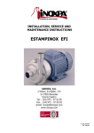
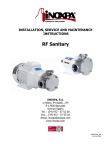
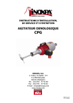
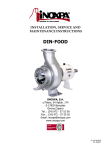
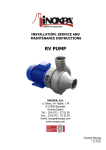
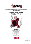
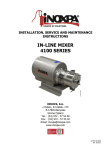
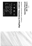
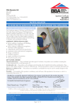
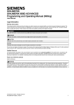
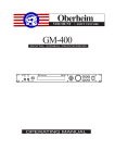
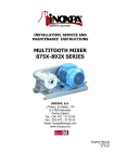
1
INSTALLATION, SERVICE AND
MAINTENANCE INSTRUCTIONS
DIN-FOOD
INOXPA, S.A.
c/Telers, 54 Aptdo. 174
E-17820 Banyoles
Girona (Spain)
Tel. : (34) 972 - 57 52 00
Fax. : (34) 972 - 57 55 02
Email: [email protected]
www.inoxpa.com
MIDF-01_EN
ED. 18.07/05
MANUFACTURER DECLARATION
According the EC directive about machines
98/37/CE, Annex II B
The manufacturer:
INOXPA, S. A.
c/ Telers, 54
17820 Banyoles (Girona) - Spain
Hereby declares, that the pumps
DIN-FOOD
CENTRIFUGAL PUMP
Denomination
Type
2005
Manufacturing year
Comply with the pertinent disposition, in the execution supplied by INOXPA, S.A. for
the incorporation in a machine or installation, or for the assembly with other machines
as a subunit of other higher order machine.
Harmonized norms used, particularly:
EN ISO 12100-1/2, EN 809
The machine above must not be put into service until the machinery into which it has
been incorporated have been declared in conformity with the EC Machinery Directive.
It must meet, particularly, the standards EN 294, EN 563, EN 809 y EN 953 in its
respective current editions.
Year of CE marking: CE 95
Banyoles, January 1995
EC DECLARATION OF CONFORMITY
According the EC directive about machines
98/37/CE, Annex II A
The manufacturer:
INOXPA, S. A.
c/ Telers, 54
17820 Banyoles (Girona) - Spain
Hereby declares, that the pump
CENTRIFUGAL PUMP
Denomination
DIN-FOOD
Type
2005
Manufacturing year
Are in conformity with the essential requirements of the Machinery Directive 98/37/CE
(latest modifications included) and according the following Council Direcitves and
harmonized norms:
- 73/23/CE Directive “low voltage”
- Norms EN ISO 12100-1/2, EN 809
Year of CE marking: CE 95
Banyoles, January 1995
1. Safety
1.1. INSTRUCTION MANUAL
This instruction manual contains information on the reception, installation, operation, fitting, stripping and maintenance for the
DIN-FOOD pump.
The information given herein is based on the most up-to-date data available.
INOXPA reserves the right to modify this instructions manual without having to give prior notice.
1.2. START-UP INSTRUCTIONS
This instruction manual contains vital and useful information for properly operating the pump and for keeping it in good
running condition.
Not only should the safety instructions set forth in this chapter be carefully read before putting the pump into operation, but
those concerned must also familiarise themselves with the operating features of the pump and strictly adhere to the
instructions given herein. It is extremely important that these instructions be kept in a set place near the installation.
1.3. SAFETY
1.3.1. Warning signs
Danger for people in general.
Danger of injury caused by rotating parts
of the equipment.
Danger! Electricity.
Danger! Caustic or corrosive agents.
Danger! Suspended loads.
Danger to the proper operating of the
machine.
Obligation to ensure safety at work.
Use of safety goggles obligatory.
1.4. GENERAL SAFETY INSTRUCTIONS
Please read the instruction manual carefully before installing and commissioning the pump. Should
you have any doubts or queries, contact INOXPA.
1.4.1. During the installation
You must always bear in mind the Technical Specifications set forth in Chapter 8.
Do not put the pump into operation before connecting it to the pipes.
Do not put the pump into operation if the cover of the pump has not been fitted and the impeller
fixed in the pump.
Check that the motor specifications are correct, especially if there is a special risk of explosion due
to the work conditions.
During the installation procedure, all the electrical work must be carried out by duly authorised
personnel.
1.4.2. During operation
You must always bear in mind the Technical Specifications set forth in Chapter 8. The limit values
that have been set must NEVER be exceeded.
NEVER touch the pump or pipes whenever the pump is being used to decant hot liquids or during the
cleaning procedure.
ED. 18.07/05
1.Safety
3
The pump has moving parts. Do not put your fingers into the pump when it is operating.
NEVER work with the suction and the delivery valves shut off.
NEVER directly sprinkle the electric motor with water. Standard motor protection is IP-55: dust and
water sprinkling protection.
1.4.3. During maintenance
You must always bear in mind the Technical Specifications set forth in Chapter 8.
NEVER strip the pump down until the pipes have been drained. Remember that there will always be
some liquid left in the pump casing (if it has not been fitted with a drain). Always remember that the
liquid that has been pumped may be dangerous or subject to high temperatures. For situations of
this type, please consult the prevailing regulations in the country in question.
Do not leave loose parts on the floor.
ALWAYS turn the power supply to the pump off before embarking on maintenance work. Take out
the fuses and disconnect the wires from the motor terminals.
All electrical work must be carried out by duly authorised personnel.
1.4.4. In accordance with the instructions
Any failure to comply with the instructions could lead to a hazard for the operators, the atmospheric conditions of the room,
and the machine, and it could lead to a loss to any right to make a claim for damages.
Such non-compliance could bring with it the following risks:
•
Important operating failures of the machine / plant.
•
Failure to comply with specific maintenance and repair procedures.
•
Potential electrical, mechanical and chemical hazards.
•
Atmospheric conditions in the room could be hazardous due to the release of chemical substances.
1.4.5. Warranty
We wish to point out that any warranty issued will be null and void and that we are entitled to an indemnity for any civil liability
claim for products which might be filed by third parties if:
•
Operation and maintenance work has not been done following the corresponding instructions; the repairs have not
been made by our personnel or have been made without our written authorization;
•
Modifications are made to our material without prior written authorization;
•
The parts or lubricants used are not original INOXPA parts/lubricants;
•
The material has been improperly used due to error or negligence or have not been used according to the indications
and the intended purpose.
•
The parts of the pump have been damaged as a result of having been exposed to strong pressure as there was no
safety valve.
The General Delivery Terms which you have already received are also applicable.
No modification can be made to the machine without the prior consent of the manufacturer. For your
safety, use spare parts and original accessories. The use of other parts exempts the manufacturer
from any and all responsibility.
Any change in operating conditions can only be done with the prior written consent of INOXPA.
In the event of doubt or should you require a fuller explanation on particular data (adjustment, assembly, disassembly...),
please do not hesitate to contact us
4
1.Safety
ED. 18.07/05
2. Index
1.
Safety
1.1. INSTRUCTION MANUAL ................................................................................................... 3
1.2. START-UP INSTRUCTIONS............................................................................................... 3
1.3. SAFETY........................................................................................................................... 3
1.4. GENERAL SAFETY INSTRUCTIONS.................................................................................... 3
2.
Index
3.
General Information
3.1. DESCRIPTION ................................................................................................................. 7
3.2. OPERATING PRINCIPLE ................................................................................................... 7
3.3. APPLICATION.................................................................................................................. 7
4.
Installation
4.1. PUMP RECEPTION ........................................................................................................... 9
4.2. TRANSPORT AND STORAGE............................................................................................. 9
4.3. LOCATION .....................................................................................................................10
4.4. COUPLING .....................................................................................................................10
4.5. PIPES ............................................................................................................................11
4.6. PRESSURE TANK ............................................................................................................11
4.7. ELECTRICAL INSTALLATION ...........................................................................................11
5.
Start-up
5.1. START-UP ......................................................................................................................13
6.
Operating problems
7.
Maintenance
7.1. GENERAL MAINTENANCE ................................................................................................15
7.2. DRY THREAD TORQUE ...................................................................................................15
7.3. OILING ..........................................................................................................................15
7.4. STORAGE.......................................................................................................................15
7.5. CLEANING......................................................................................................................16
7.6. PUMP DISASSEMBLY/ASSEMBLY......................................................................................17
8.
Technical Specifications
8.1. TECHNICAL SPECIFICATIONS .........................................................................................22
8.2. WEIGHTS.......................................................................................................................22
8.3. DIN-FOOD DIMENSIONS (BARESHAFT) ...........................................................................23
8.4. DIN-FOOD DIMENSIONS (BARESHAFT WITH BASE PLATE)...............................................24
8.5. DIN-FOOD DIMENSIONS (MONOBLOCK)..........................................................................24
8.6. DIN-FOOD DIMENSIONS (MONOBLOCK WITH CAPOT) .....................................................26
8.7. DIN-FOOD PUMP (BARESHAFT).......................................................................................27
ED. 18.07/05
2.Index
5
8.8. DIN-FOOD PUMP (MONOBLOCK) .................................................................................... 28
8.9. DIN-FOOD PUMP SECTION (BARESHAFT) ....................................................................... 29
8.10. PARTS LIST DIN-FOOD PUMP (BARESHAFT) ................................................................. 30
8.11. DIN-FOOD PUMP SECTION (MONOBLOCK).................................................................... 31
8.12. PARTS LIST DIN-FOOD PUMP (MONOBLOCK)................................................................ 32
8.13. DIN-FOOD FLUSHED MECHANICAL SEAL....................................................................... 33
8.14. DIN-FOOD DOUBLE MECHANICAL SEAL ........................................................................ 34
6
2.Index
ED. 18.07/05
3. General Information
3.1. DESCRIPTION
INOXPA DIN-FOOD series centrifugal pumps with volute that made of a pump housing of thick plate, which has been cold
pressed. The parts that come in contact with the product are made of AISI316L stainless steel with a Ra = 0.8µm interior
finish.
The DIN-FOOD pump is built as monoblock unit with volute motor casing, axial suction and radial impeller, while the
connections are DIN-11864-2-B PN-10 flanges. The pump impeller has been designed as a single-bodied, half-open doublecurved part. The mechanical seal is balanced and completely sanitary, the springs are protected in order to prevent their
contact with the product. The friction surfaces are made of silicon carbide, graphite and EPDM joints in the standard version.
The motor is designed in accordance with IEC Standards, has IP-55 protection and Class F insulation. Three-phase 220-240 /
380-420 or 380-420 / 660 V feed at 50 Hz, in accordance with power supply. Motors adapted to operate under explosive
conditions can be supplied upon request. In accordance with the prevailing environmental conditions, the motors can be
explosion proof (EExd) or have increased safety features (EExe).
The DIN-FOOD series has been especially designed to comply with all the hygienic demands required by the food industry.
As far as hygiene, reliability and robustness are concerned, the whole range meets all of the requisites demanded by
aforementioned industries. Due to its design qualities, optimum interchangeability is to be had between parts.
3.2. OPERATING PRINCIPLE
The pump impeller, housed in the pump housing, turns along with the pump shaft. It is fitted with a certain number of blades
in accordance with the model of pump chosen.
Given this design, the impeller blades transmit both pressure and kinetic energy to the fluid in question.
The pump cannot be reversed by simply changing of the rotation direction. The rotation direction, to be seen from the rear of
the motor, should be clockwise.
3.3. APPLICATION
In general terms, DIN-FOOD pumps, at least in their standard version, are mainly used in the food industry to decant liquids.
Each different type of pump has special hydraulic features in accordance with the pump impeller diameter and various speeds.
In the curves reflecting the characteristics, we are also given the required NPSH and the absorbed power.
3.3.1. Field of application
ED. 18.07/05
3.General Information
7
Each pump has a limited field of application. The pump in question was selected for certain pumping
conditions at the time the order was made. INOXPA is not liable for any damages that might arise if
the information furnished by the purchaser is incomplete (nature of the liquid, RPM…).
8
3.General Information
ED. 18.07/05
4. Installation
4.1. PUMP RECEPTION
INOXPA is not responsible for any deterioration of the material as a result of its transportation or
unpacking. Visually check that the packing has not suffered any damage.
The pump will be accompanied by the following documentation:
•
Dispatch notes.
•
Pump Instruction and Service Manual.
•
Motor Instruction and Service Manual (*).
•
(*) If the pump has been supplied with a motor from INOXPA.
Unpack the pump and check the following:
• The pump suction and delivery connections, removing the
remains of any packing material.
• Check that the pump and the motor have not suffered any
damage.
• Should the pump not be in proper condition and/or does
not have all the parts, the haulier must draw up a report as
soon as possible with regard to the same.
4.1.1. Pump identification and marking
Serial number
Pump plate
4.2. TRANSPORT AND STORAGE
DIN-FOOD pumps are quite often too heavy to be put into their storage space manually.
Lift the pump as is shown below:
ED. 18.07/05
4.Installation
9
4.3. LOCATION
•
Position the pump as near as possible to the suction tank, and whenever possible below the level of the liquid.
•
Place the pump in such a way that there is enough space around it to provide access both to the same and to the motor.
(See Chapter 8. Technical Specifications to consult dimensions and weights).
•
Place the pump on a level and flat surface.
•
The basement must be rigid, horizontal and against any vibration.
Install the pump in such a way that it can be properly ventilated. If the pump is to be installed
outside, it must be done so under cover. Its positioning must enable easy access for any inspection
and maintenance operations that may need to be carried out.
4.4. COUPLING
For the couplings selection and assembly consult to the supplier manual. Sometimes the torque of the positive displacement
pumps can be high enough. Therefore, a coupling have been chosen 1.5 to 2 the adequate torque.
Alignment.
The pump and motor shaft of complete units have been accurately pre-aligned in our factory.
After installations of the pump unit, the pump and motor shaft should be re-aligned.
Place a straight-edge (A) on top of the coupling: the straight should make contact with both halves of the coupling over their
entire length. See figure.
Repeat the check, but this time on both sides of the coupling near the shaft. For the sake of accuracy, this chech should also
be done using an outside caliper (B) at two diametrically opposite points on the outside surfaces of the two halves of the
coupling.
Maximum alignment deviations:
Outside diameter of
the coupling [mm.]
70 - 80
81 - 95
96 - 110
111 - 130
131 - 140
141 - 160
161 - 180
181 - 200
201 - 225
10
Va min.
[mm.]
2
2
2
2
2
2
2
2
2
Va max.
[mm.]
4
4
4
4
4
6
6
6
6
4.Installation
Va max. - Va min.
[mm.]
0,13
0,15
0,18
0,21
0,24
0,27
0,3
0,34
0,38
Vr. [mm.]
0,13
0,15
0,18
0,21
0,24
0,27
0,3
0,34
0,38
ED. 18.07/05
4.5. PIPES
• In general, suction and delivery pipes should be fitted in straight stretches, with the minimum amount of elbows and
accessories, in order reduce, as far as possible, any load loss that might be produced by friction.
• Make sure that the pump mouths are well aligned with respect to the piping, and that they are similar in diameter to that of
the pipe connections.
• Position the pump are near as possible to the suction tank, and whenever possible below the level of the liquid, or even
lower with respect to the tank in order for the static suction head be at its maximum.
• Place brackets for the piping as near as possible to the suction and delivery mouths of the pump.
4.5.1. Shut-off valves
The pump can be isolated for the purpose of carrying out maintenance work. To this end, shut-off valves should be fitted at the
pump’s suction and delivery connections.
These valves must ALWAYS be open whenever the pump is operating.
4.6. PRESSURE TANK
For models with double mechanical seal will be necessary the installation of a pressure tank.
Install ALWAYS the pressure tank between 1 and 2 meters above the mechanical seals. See the
figure 4.6.1.
1...2m
Connect ALWAYS the refrigeration liquid input connection with the bottom chamber seal connection.
So, the refrigeration liquid outlet will be carried out by the top chamber connection. See the figure
4.6.1.
Mechanical seal
Figure 4.6.1: Pressure tank connection lay out
To obtain further information about the pressure tank (installation, operation, maintenance, … ), consult the instruction manual
supplied by the manufacturer.
4.7. ELECTRICAL INSTALLATION
Leave the connecting of the electrical motors to qualified personnel. Take the necessary measures to
prevent any breakdowns in the connections and wires.
The electrical equipment, the terminals and the components of the control systems may still carry an
electric charge even when disconnected. Contact with them may put the safety of operators at risk,
or cause irreparable damage to the material.
Before manoeuvring the pump, make sure that the electric box is switched off.
ED. 18.07/05
4.Installation
11
•
•
Connect the motor in accordance with the instructions supplied by the manufacturer of the same.
Check the direction of the rotation (see the signaling label on the pump).
Put the pump motor into operation momentarily. Make sure, by looking at the pump from
the rear, that the motor’s ventilator is rotating in a clockwise direction.
Check ALWAYS the direction of the motor’s rotation with liquid inside the pump.
For the models with sealing chamber, make sure always that it is filed of liquid before checking the
rotating direction.
12
4.Installation
ED. 18.07/05
5. Start-up
Before putting the pump into operation read carefully the instructions on installation given in
Chapter 4. Installation.
5.1. START-UP
Read Chapter 8. Technical Specifications carefully. INOXPA will not assume responsibility for any
improper or incorrect use of the equipment.
Do not touch the pump or the piping while it is pumping products at a high temperature.
5.1.1. Checks to be carried out before putting the pump into operation
• Completely open the pipes’ suction and delivery shut-off valves.
• Check oil level of the pump. Add correct grade of oil as necessary to maintain level in center of oil sight glass (In the case of
first start-up: pumps are shipped with oil in the gearbox, nevertheless this check may be skipped).
• If the liquid fails to flow toward the pump, fill it with the liquid to be pumped.
The pump must NEVER rotate without liquid.
• Check that the rotation direction of the motor is correct.
5.1.2. Checks to be carried out on putting the pump into operation
• Check to make sure that the pump is not making any strange noises.
• Check to see if the absolute inlet pressure is sufficient, in order to avoid cavitations in the pump. Consult the curve for the
minimum required pressure above the steam pressure (NPSHr).
• Monitor the delivery pressure.
• Check that there are no leaks in the sealed areas.
A shut-off valve should not be used in the suction pipe to regulate the flow rate. It must be
completely open during operation.
Monitor motor consumption in order to avoid a circuit overload.
Reduce the flow and the power consumed by the motor:
• Regulating the flow to the pump delivery.
• Decreasing motor speed.
ED. 18.07/05
5.Start-up
13
6. Operating problems
The table given below provides solutions to problems that might arise during pump operation. With respect to the same, it is
assumed that the pump has been properly installed and has been correctly selected for the application in question.
Should there be a need for technical service please contact INOXPA.
Operating problems
Probable causes
Overloading of motor.
Insufficient flow rate or pressure in pump.
No pressure on the discharge side.
Irregular discharge flow rate / pressure.
Noise and vibrations.
The pump gets clogged.
Overheating of the pump.
Abnormal wear.
Leak in mechanical seal.
8, 9, 13, 20, 21, 22, 23, 24.
1, 2, 4, 5, 7, 9, 10, 17, 19.
2, 3, 6, 18.
1, 2, 4, 5, 6, 9.
2, 4, 5, 6, 7, 8, 9, 10, 13, 14,15, 20, 21, 22, 23, 24.
9, 10, 13, 15, 20, 21, 22, 24.
8, 9, 10, 13, 15, 20, 21, 22, 23, 24.
4, 5, 10, 15, 20, 24.
11, 12, 16.
Probable causes
Solutions
1
2
Wrong rotation direction.
Insufficient NPSH.
3
4
5
6
7
Non-purged pump.
Cavitation.
The pump is sucking air.
Obstructed suction piping.
Delivery pressure is too high.
8
Flow is too high.
9
10
11
12
The viscosity of the liquid is too high.
The temperature of the liquid is too high.
Mechanical seal either damaged or worn.
Unsuitable O-ring for the liquid in question.
13
The impeller is rubbing.
14
15
16
17
18
19
Pressure in the pipes.
There are foreign bodies in the liquid.
The tension of the mechanical seal spring is too low.
The pump speed is too low.
The suction shutoff valve is closed.
Delivery pressure is too low.
20
21
22
23
24
Worn bearing.
Not enough lubricating oil.
Unsuitable lubricating oil.
Non aligned coupling.
Pump and/or motor not fixed to the base-plate.
Change the direction of the rotation.
Increase the NPSH available:
- Raise the suction tank.
- Lower the pump.
- Decrease the steam tension.
- Increase the diameter of the suction piping.
- Shorten and simplify the suction piping.
Purge or fill.
Increase the suction pressure.( See Number 2 also)
Check the suction piping and all of its connections.
Check the suction piping and the filters, if there are any.
If necessary, decrease the load losses by increasing the diameter
of the piping, for example.
Decrease the flow:
- Reduce the flow by means of a diaphragm.
- Partially close off the delivery valve.
- Trim the impeller.
- Decrease the speed.
Decrease the viscosity by heating the liquid, for example.
Decrease the temperature of the liquid by cooling it.
Replace the seal.
Fit more suitable O-ring by consulting the supplier with respect to
the same.
- Lower the temperature.
- Lower suction pressure.
- Adjust impeller / cover set.
Connect the pipes to the pump without pressure.
Place a filter at the suction piping.
Adjust in accordance with the instructions given herein.
Increase the speed.
Check and open.
Increase the pressure:
- Increase the diameter of the impeller.
- Increase pump speed.
Replace the bearings; check the pump.
Fill with oil.
Use adequate oil.
Align coupling.
Affix the pump and/or the motor to the base-plate, check to see if
the pipes are connected without pressure and align the coupling.
If the problems persist stop using the pump immediately. Contact the pump manufacturer or his
representative.
14
6.Operating problems
ED. 18.07/05
7. Maintenance
7.1. GENERAL MAINTENANCE
This pump, as with any other machine, needs to be maintained. The instructions contained in this manual deal with the
identification and replacement of the spare parts. These instructions have been drawn up by maintenance staff and are
destined for those people who are responsible for supplying spare parts.
Read carefully Chapter 8. Technical specifications.
All the parts or materials that are changed must be duly eliminated/recycled in accordance with the
prevailing directives in each area.
ALWAYS disconnect the pump before starting out on any maintenance work.
7.1.1. Check the mechanical seal
Periodically check that there are no leaks in the shaft area. Should there be any leaks in the mechanical seal area, replace the
same pursuant to the instructions given in the section entitled Stripping and Assembly of the pump.
7.2. DRY THREAD TORQUE
Material
Dry thread torque [N.m.]
M5
M6
M8
M10
M12
M14
M16
M18
M20
8.8
6
10
25
49
86
135
210
290
410
A2
5
9
21
42
74
112
160
210
300
7.3. OILING
The bearings are oiled by immersion in an oil bath.
The pumps are supplied with oil.
• Regularly check the oil level, for example, weekly or eery 150 operating hours.
• The first oil change must be carried out after 150 hours of operation.
• Afterwards, it can be changed every 2500 operating hours or at least once a year when operating under normal conditions.
When change the oil: the oil sump must be filled up to the level in the middle of the peephole.
Do not pour too much oil into the sump.
Leave the pump switched off for a while and then re-check the oil level; if necessary, add a little oil.
Oils for environment temperatures of 5 to 50ºC: ISO VG 68
PUMP TYPE
Quantity of oil in
the support (l.)
125-100-250
125-100-315
125-100-400
150-125-250
150-125-315
150-125-400
200-150-250
1,75
200-150-315
200-150-400
2
7.4. STORAGE
Before being stored the pump must be completely emptied of liquids. Avoid, as far as possible, the exposure of the parts to
excessively damp atmospheres.
ED. 18.07/05
7.Maintenance
15
7.5. CLEANING
The use of aggressive cleaning products such as caustic soda and nitric acid may give rise to skin
burns.
Use rubber gloves during the cleaning process.
Always use protective goggles.
If the pump is installed in a system fitted with a CIP process, there will be no need for stripping.
If it is not fitted with an automatic cleaning process, strip the pump pursuant to the instructions given in the section entitled
Stripping and Assembly of the pump.
Cleaning solutions for CIP processes.
Only use clear water (chloride free) to mix with the cleaning agents:
a) Alkaline solution:
1% in weight of caustic soda (NaOH) to 70ºC (150ºF)
1 Kg NaOH + 100 l. water = cleaning solution
or
2.2 l. NaOH al 33% + 100 l. of water = cleaning solution
b) Acid solution:
0.5% in weight of nitric acid (HNO3) to 70ºC (150ºF)
0.7 liters HNO3 to 53% + 100 l. water = cleaning solution
Monitor the concentration of cleaning solutions, it could give rise to the deterioration of the pump
sealing gaskets.
In order to remove any remains of cleaning products, ALWAYS rinse the element in question with clean water after completing
the cleaning process.
16
7.Maintenance
ED. 18.07/05
7.6. PUMP DISASSEMBLY/ASSEMBLY
7.6.1. Pump casing and impeller
Disassembly
Remove the hexagonal screws (52) and washers (53) that fix the pump housing (01) to the lantern (04). Remove the impeller
blind nut (45) and the O-ring (80D), then take the impeller out (02).
Assembly
Slip the impeller (02) onto the shaft (05) until it reaches the rotational part of the mechanical seal (08), fit the O-ring (80D)
into the blind nut slot (45) and tighten the nut (45). Fit the pump housing (01) and fix it to the lantern (04) with the hexagonal
screws (52) and the washers (53).
¡IMPORTANT! When assembling the new seal, be careful and mount the
parts and the O-rings with soapy water in order to allow an easy glide of the
parts, either the stationary part and the rotary part on the shaft.
ED. 18.07/05
7.Maintenance
17
7.6.2. Simple mechanical seal
Disassembly
Remove the rotational part from the mechanical seal (08).
Take off the pump cover (03), the fixed part of the mechanical seal (08) will remain housed in the cover.
Remove the fixed part of the mechanical seal (08).
Assembly
Check the situation of the shaft (05) in relation to the pump cover (03). See the chapter 7.6.5. Shaft pump fitting.
Fit the pump cover (03) to the lantern (04).
Place the fixed part of the mechanical seal in the cover housing (03) taking the stud into account.
Check to make sure that the assembly measurement is that which is given below:
Slide the rotating part of the mechanical seal (08) over the shaft (05) until it
can go no further.
18
Seal
diameter
53
34,5
60
37,5
A
7.Maintenance
ED. 18.07/05
7.6.3. Flushed mechanical seal
Disassembly
Remove the rotating part of the mechanical seal (08).
Take off the pump cover (03) leaving the ring (30) and the lid (10) as they are. The fixed parts of the mechanical seal (08,
08B) will remain housed in the group.
Remove the fixed part from the inner seal (08) taking the stud into account.
Remove the screws (52C), the fixed part of the outer seal will come out (08B).
Loosen the studs (55A) in order to remove the rotating part from the outer seal (08A) with the sleeve (13).
Assembly
Check the situation of the shaft (05) in relation to the pump cover (03). See the chapter 7.6.5. Shaft pump fitting.
Fit the sleeve (13) until it can go no further on the shaft (05).
Fit the rotating part of the outer mechanical seal (08A) with the gasket and spring on the sleeve (13) and fix the shaft (05) by
means of the studs (55A).
Position the O-ring (80B) on the pump cover centering (03).
Fit the lid (10) in this centering, the fixed part of the outer seal
(08B), the cool seal ring (30) and fix the whole to the pump cover
(03) by means of the hexagonal screws (52C).
Carefully fit this whole group to the lantern center (04). At the same
time, the two rub faces of the outer seal will touch (08A, 08B).
See the section on the assembly of the simple mechanical seal in
order to fit the inner mechanical seal.
ED. 18.07/05
Seal
diameter
53
34,5
60
37,5
A
7.Maintenance
19
7.6.4. Double mechanical seal
Disassembly
Remove the shaft separator (17).
Remove the screws (52C), thus freeing the external cover (10B).
Remove the group of the three fitted covers (03A, 10A and 10C), the fixed part of the inner mechanical seal (08) will remain
housed in the internal cover (10C).
Loosen the screws (52D) to strip the internal cover (10C) and the double seal lid (10A) from the pump cover (03A).
Loosen the studs from the rotating parts of the seals. Then, remove these rotating parts from the mechanical seals (08, 08A) of
the shaft (05A).
Remove the external cover (10B), the fixed part of the exterior mechanical seal (08A) will remain housed in the cover.
Assembly
Check the situation of the shaft (05) in relation to the pump cover (03). See the chapter 7.6.5. Shaft pump fitting.
Position the fixed part of the mechanical seal (08A) in the cover housing (10B), taking the stud into account.
Fit into the external cover (10B), leaving it loose at the end of the shaft (05A).
Slip on the rotating part of the outer mechanical seal (08A). Fix in
accordance with the assembly dimensions indicated.
Fit the rotating part of the internal mechanical seal (08) up to the
outer seal (08A), and then fix it.
Place the fixed part of the internal seal (08) into the cover housing
(10C), taking the stud into account.
Fit the covers (03A, 10A and 10C) by means of the screws (52D).
Position the aforementioned covers in the lantern (04) and fix the
external cover (10B) with the screws (52C).
Fit the separator (17) up to the back of the shaft (05A).
20
Seal
diameter
53
A
62,5
60
68
7.Maintenance
ED. 18.07/05
7.6.5. Shaft pump fitting
Check that the shaft (05) assembly dimension in relation to the pump cover (03) is in accordance with the indicated below:
Tipo
bomba
250
Diámetro
cierre
53
16
300
53
8
400
60
20
A
Otherwise adjust the assembly dimension in accordance with the indicated below.
• For monoblock models; loosen the studs (55) and slide the shaft (05) until it can go no further. Finally, fix the studs.
• For bareshaft models; loosen the hexagonal screws (52A) and the nuts (54), adjust the assembly dimension by means of
the studs (55). Once time it has been adjusted, fix the studs (54) and the screws (52A).
7.6.6. Lantern and motor (MONOBLOCK)
Disassembly
Remove the hexagonal screws (52A), the nuts (54) and the washers (53, 53A). Then, the lantern (04) could be removed.
Loosen the studs (55) and remove the shaft (05).
Remove the screws (52B), the nuts (54A) and the washers (53B). Then, the motor (93) could be removed from the base plate.
Assembly
Place the motor (93) on the base plate (38) and fix them by means of the screws (52B), the nuts (54) and the washers (53B).
Slide the shaft (05) over the motor shaft (93) until it can go no further. Fix the studs (55).
Place the lantern (04) on the motor (93) and fix them by means of hexagonal screws (52A), the nuts (54) and the washers
(53) and (53A).
ED. 18.07/05
7.Maintenance
21
8. Technical Specifications
8.1. TECHNICAL SPECIFICATIONS
50Hz
-1
Maximum flow rate (1450 min ) ..............................................
Maximum differential pressure ................................................
Maximum suction pressure ......................................................
Maximum operating pressure ..................................................
Operating temperature ...........................................................
Maximum speed .....................................................................
Suction / delivery connections .................................................
60Hz
3
1000 m /h
6 bar (87 PSI)
14 bar (203 PSI)
20 bar (290 PSI)
-10 ºC a +140ºC (EPDM)
14 ºF a 284 ºF (EPDM)
1450 min-1
DIN 11864-2 (estándar)
1000 m3/h
9 bar (131 PSI)
11 bar (160 PSI)
20 bar (290 PSI)
-10 ºC a +140ºC (EPDM)
14 ºF a 284 ºF (EPDM)
1750 min-1
DIN 11864-2 (estándar)
Whenever the noise level in the area of operation exceeds 85 dB(A) use special protection.
Materials
Parts in contact with the product ...............................................
Other parts in stainless steel .....................................................
Gaskets and joints in contact with the product ...........................
Other optional joints materials ..................................................
Surface finish ..........................................................................
Mechanical seal
Seal type ................................................................................
Flushed mechanical seal
Maximum pressure ..................................................................
Flow .......................................................................................
Double mechanical seal
Operating pressure..................................................................
Mechanical seal
materials
AISI 316L
AISI 304
EPDM (standard)
Consult your supplier
Standard finish
Single internal mechanical seal
1 bar (14,5 PSI)
6-10 l/min
1,5~2 bar (22~29 PSI) over the pump
operating pressure
Type of mechanical seal
Flushed
Double [ atmospheric side ]
Graphite
Silicon carbide
Single internal
Stationary part
Rotary part
Double [ product side ]
Silicon carbide
8.2. WEIGHTS
Pump Type
- bareshaft -
22
125-100-250
Weight
[Kg]
113
Weight
[lbs]
249
125-100-315
127
280
125-100-400
135
298
150-125-250
118
260
150-125-315
133
293
150-125-400
149
329
200-150-250
124
273
200-150-315
194
428
200-150-400
210
463
Pump Type
- monoblock 125-100-250
150-125-250
200-150-250
8.Technical Specifications
MOTOR
Weight
[Kg]
Weight
[lbs]
160
204
449
180
239
526
160
210
462
180
256
563
180
263
579
200
360
792
ED. 18.07/05
8.3. DIN-FOOD DIMENSIONS (BARESHAFT)
DIN 11864-2-A flange dimensions
PUMP TYPE
DN
D
k
d4
100
159
137
117
125
183
161
142
150
213
188
168
200
263
238
218
DNa
DNi
d
l
125-100-250
125-100-315
125
100
42
110
a
121
125-100-400
130
150-125-250
128
150-125-315
150
125
42
110
150-125-400
140
200-150-250
200-150-315
200-150-400
ED. 18.07/05
137
42
200
150
48
142
110
153
d2
8 x ∅11
8 x ∅14
f
h1
h2
522
250
316
280
352
330
402
250
355
280
372
330
422
537
250
375
670
280
402
667
330
452
510
530
518
b
m1
m2
90
160
120
100
200
90
100
90
100
8.Technical Specifications
n1
n2
440
350
490
400
150
550
450
23
160
120
440
350
18
200
150
490
400
550
450
440
350
490
400
550
450
200
150
n3
110
110
s1
18
23
110
140
s2
363
14
350
370
14
14
23
w
18
358
378
500
498
23
8.4. DIN-FOOD DIMENSIONS (BARESHAFT WITH BASE PLATE)
PUMP TYPE MOTOR DNa
125-100-250
150-125-250
200-150-250
125-100-315
150-125-315
200-150-315
125-100-400
150-125-400
200-150-400
24
160
160
180
160
160
180
180
160
180
180
200
160
160
180
180
200
160
180
180
200
225
160
180
200
225
250
280
200
225
250
280
225
250
280
280
315
225
250
280
280
315
315
315
M
L
M
M
L
M
L
L
M
L
L
M
L
M
L
L
L
M
L
L
L
M
L
125
150
200
125
150
200
DNi
100
125
150
100
125
150
a
121
128
142
121
137
153
M
S
L
M
S
M
S
M
S
M
S
M
S
M
L
125
150
200
100
125
150
130
140
153
f
1250
1290
1330
1265
1305
1345
1365
1330
1365
1385
1405
1240
1280
1315
1335
1355
1305
1340
1360
1380
1490
1470
1510
1550
1660
1725
1820
1365
1475
1540
1705
1495
1560
1725
1785
1790
1655
1720
1885
1945
1950
2090
2120
h1
h2
b
316
35
l
550
m1
m2
m3
n1
n2
1300
1020
620
565
1350
990
s
w
1335
565
550
355
40
1340
565
340
140
550
375
35
565
620
1335
580
352
35
595
1385
650
580
372
30
370
45
595
650
670
580
595
650
180
1380
23
1395
720
1545
1500
1140
1735
1700
1300
1370
1350
990
1520
1710
1380
1530
1500
1700
1350
1500
1140
1300
990
1140
870
1720
1700
1300
935
1820
1800
1400
720
1545
1500
1140
665
670
402
35
20
420
820
700
720
10
870
30
720
422
20
430
45
420
452
870
1735
1700
1300
935
1835
1800
1400
200
180
200
180
200
820
765
720
665
820
765
180
35
430
200
8.Technical Specifications
ED. 18.07/05
8.5. DIN-FOOD DIMENSIONS (MONOBLOCK)
DIN 11864-2-A flange dimensions
DN
D
k
d4
100
159
137
117
125
183
161
142
150
213
188
168
200
263
238
218
PUMP TYPE
125-100-250
MOTOR DNa DNi
160
a
125 100 121
180
150-125-250
160
180
200
ED. 18.07/05
8 x ∅11
8 x ∅14
f
h1
850
h2
b
c
c1
150 125 128
865
l
475
250
90
68
355
965
1005 340
m1
m2
n1
n2
n3
n4
s1
s2
160 120
367
18
440 350 415 470
18
200
68
88
400 305 585 210
8.Technical Specifications
349
374
475
375
w
342
360 260 460
945
200 150 142
c2
460
316
930
180
200-150-250
d2
150
381
23
600 545 545 600
23
384
25
8.6. DIN-FOOD DIMENSIONS (MONOBLOCK WITH CAPOT)
DIN 11864-2-A flange dimensions
DN
D
k
d4
100
159
137
117
125
183
161
142
150
213
188
168
200
263
238
218
PUMP TYPE
125-100-250
MOTOR DNa DNi
160
a
125 100 121
d2
8 x ∅11
8 x ∅14
f
h1
960
h2
b
c
c1
c2
l
160
m2
n1
n2
n3
n4
s2
250
975
90
68
360 260 525
369
18
440 350 415 470
18
355
180
200-150-250
180
200
26
w
344
160 120
150 125 128
s1
316
180
150-125-250
m1
351
376
200 150 142
995
1105 340
200
375
68
88
400 305 690 210
8.Technical Specifications
150
383
23
600 545 545 600
23
386
ED. 18.07/05
8.7. DIN-FOOD PUMP (BARESHAFT)
ED. 18.07/05
8.Technical Specifications
27
8.8. DIN-FOOD PUMP (MONOBLOCK)
28
8.Technical Specifications
ED. 18.07/05
8.9. DIN-FOOD PUMP SECTION (BARESHAFT)
ED. 18.07/05
8.Technical Specifications
29
8.10. PARTS LIST DIN-FOOD PUMP (BARESHAFT)
Position
Description
Quantity
Material
01
Pump housing
1
AISI 316L
02
Impeller
1
AISI 316L
03
Pump cover
1
AISI 316L
04
Lantern
1
GG-15
05
Shaft
1
AISI 316L
06
Bearing support
1
GG-15
07
Leg
1
GG-15
08
Mechanical seal
1
-
12
Bearing house
1
F-114
12A
Bearing cover
1
F-114
18
Front cover gasket
1
Paper gasket
45
Blind nut
1
AISI 316L
47A
Protection
2
AISI 304
50A
Screw
4
A2
51
Allen screw
6
8.8
51A
Allen screw
4
8.8
52
Hexagonal screw
12
A2
52A
Hexagonal screw
6
8.8
52B
Hexagonal screw
2
A2
53
Grower washer
12
A2
53A
Grower washer
2
A2
54
Hexagonal nut
3
8.8
55
Stud
3
8.8
61
Key
1
A2
61A
Key
1
F-114
62
Safety nut
1
Steel
63
Safety washer
1
Steel
66
Elastic ring
1
Steel
70
Double angular contact bearing
1
Steel
Cylindrical roller bearing
1
Steel
O-ring
1
EPDM
70A
80
30
80A
O-ring
1
EPDM
80B
O-ring
1
NBR
80D
O-ring
1
EPDM
85
Oil plug
1
AISI 303
86
Peephole
1
Plastic
87
Bleeder
1
Plastic
88
Lip seal
1
NBR
88A
Lip seal
1
NBR
8.Technical Specifications
ED. 18.07/05
8.11. DIN-FOOD PUMP SECTION (MONOBLOCK)
ED. 18.07/05
8.Technical Specifications
31
8.12. PARTS LIST DIN-FOOD PUMP (MONOBLOCK)
32
Position
Description
Quantity
Material
01
Pump housing
1
AISI 316L
02
Impeller
1
AISI 316L
03
Pump cover
1
AISI 316L
04
Lantern
1
GG-15
05
Shaft
1
AISI 316L
08
Mechanical seal
1
-
38
Base plate
1
AISI 304
45
Blind nut
1
AISI 316L
47A
Protection
2
AISI 304
50A
Screw
8
A2
52
Hexagonal screw
8
A2
52A
Hexagonal screw
4
A2
52B
Hexagonal screw
4
A2
53
Grower washer
12
A2
53A
Flat washer
4
A2
53B
Flat washer
4
A2
54
Hexagonal nut
4
A2
54A
Hexagonal nut
4
A2
55
Stud
2
A2
61
Key
1
A2
80A
O-ring
1
EPDM
80D
O-ring
1
EPDM
93
Motor
1
-
8.Technical Specifications
ED. 18.07/05
8.13. DIN-FOOD FLUSHED MECHANICAL SEAL
ED. 18.07/05
Position
Quantity
Description
08A
1
Mechanical seal - rotary part -
-
08B
1
Mechanical seal - stationary part -
-
10
1
Lid
AISI 316L
13
1
Flushed mechanical seal sleeve
AISI 316L
30
1
Flushed mechanical seal ring
AISI 316L
52C
4
Hexagonal screw
A2
55A
3
Stud
A2
80B
1
O-ring
92
2
Elbow connection
8.Technical Specifications
Material
EPDM
AISI 316
33
8.14. DIN-FOOD DOUBLE MECHANICAL SEAL
34
Position
Quantity
Description
Material
03A
1
Pump cover
AISI 316L
05A
1
Shaft
AISI 316L
08
1
Internal mechanical seal
-
08A
1
External mechanical seal
-
10A
1
Double mechanical seal lid
AISI 316L
10B
1
External cover
AISI 316L
10C
1
Internal cover
AISI 316L
AISI 316L
17
1
Separator
52C
4
Hexagonal screw
A2
52D
4
Hexagonal screw
A2
80B
2
O-ring
EPDM
80C
1
O-ring
EPDM
80D
2
O-ring
EPDM
92
2
Elbow connection
8.Technical Specifications
AISI 316
ED. 18.07/05
NOTES
INOXPA, S.A.
C/ Telers, 54 - PO Box: 174
Tel: (+34) 972 575 200
Email: [email protected]
17820 BANYOLES (Girona - Spain)
Fax: (+34) 972 575 502
Web: www.inoxpa.com
Gsm: (+34) 629 807 300
BARCELONA – FLUAL, S.L.
Tel: 937 297 280
Email: [email protected]
MADRID – INOXFLUID, S.L
Tel: 918 716 084
Email: [email protected]
BILBAO – STA, S.L.
Tel: 944 572 058
Email: [email protected]
VALENCIA – INOXDIN, S.L.
Tel: 963 170 101
Email: [email protected]
VALLADOLID – ALTAFLUID, S.L.
Tel: 983 403 197
Email: [email protected]
JEREZ – CORFLUID, S.L.
Tel: 956 140 193
Email: [email protected]
ZARAGOZA – FLUAL, S.L.
Tel: 976 591 942
Email: [email protected]
LA RIOJA – STA, S.L.
Tel: 941 228 622
Email: [email protected]
SEVILLA – CORFLUID, S.L.
Tel: 954 296 852
Email: [email protected]
CÓRDOBA – CORFLUID, S.L.
Tel: 957 326 542
Email: [email protected]
LA MANCHA – INOXFLUID, S.L.
Tel: 926 514 190
Email: [email protected]
ASTURIAS – STA, S.L.
Tel: 985 267 553
Email: [email protected]
INOXPA FRANCE, S.A. - AGENCE NORD
AGENCE RHÔNE-ALPES
2, Avenue Saint Pierre
59118 WAMBRECHIES (France)
Tel: 33(0)320 631000
Fax: 33(0)320 631001
Email: [email protected]
Z.l. Chapotin Nord
CHAPONNAY 69970 (France)
Tel: 33(0)472 709090
Fax: 33(0)472 709091
Email: [email protected]
AGENCE SUD EST
Route d’Olonzac
11200 HOMPS (France)
Tel: 33(0)468 278680
Fax: 33(0)468 278681
Email: [email protected]
AGENCE OUEST
ZA des Roitelières
44330 LE PALLET (France)
Tel: 33(0)228 010172
Fax: 33(0)228 010173
Email: [email protected]
INOXPA SKANDINAVIEN A/S
H∅egh Guldbergsgade 27
HORSENS DK-8700 (Denmark)
Tel: (45) 76 28 69 00
Fax: (45) 76 28 69 09
Email: [email protected]
INOXPA ITALIA S.R.L.
Via Kennedy, 13
RODANO (MILAN) 20090 (Italia)
Tel: 39(0)02 95327292
Fax: 39(0)02 95327168
Email: [email protected]
INOXPA SWEDEN
Stationsvägen 2
430 63 HINDÅS
Tel. +46 (0) 301 21122
Fax +46 (0) 301 21125
Email: [email protected]
INOXPA (UK) LTD
Unit 2, Ashfield Close, Whitehall
Industrial Estate LEEDS
WEST YORKSHIRE, LS12 5JB
(United Kingdom)
Tel: 44(0) 1132 636367
Fax: 44(0) 1132 636384
Email: [email protected]
INOXPA SOUTH AFRICA (PTY) LTD
48 Marconi Road Montague Gardens
CAPE TOWN 7441
(Republic of South Africa)
Tel: 27(0)21 5514533 / 1571
Fax: 27(0)21 5514534
Email: [email protected]
S.T.A. PORTUGUESA LDA.
Zona Industrial - Lugar do Guardal
ALGERIZ. 3730-266 VALE DE CAMBRA
(Portugal)
Tel: 351 256 472722
Fax: 351 256 425697
Email: [email protected]
INOXPA POLAND sp z o.o.
Ul. Arkonska, 54
80-392 Gdansk
(Poland)
Tel. +48 58 511 00 05
Fax +48 58 556 72 51
Email: [email protected]
INOXPA USA, Inc
3715 Santa Rosa Avenue Suite A4
Santa Rosa, CA95407
(California)
Tel. 1.707.585.3900
Fax 1.707.585.3908
Email: [email protected]
INOXPA DEUTSCHLAND
Email: [email protected]
Además de nuestras delegaciones, INOXPA opera con una red de distribuidores independientes que comprende un total de más de 50 países en
todo el Mundo.
Para más información consulte nuestra página web.
www.inoxpa.com