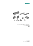
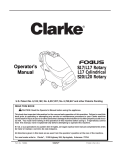
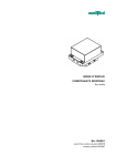
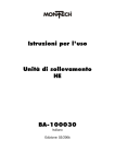
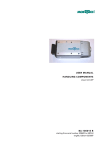
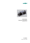
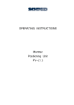
1
Safety Devices
OPERATING INSTRUCTIONS
Barrier:
SW
Edition:
BA-100026
03/2008
Contents
Important Information
EC Certificate of Conformity ..................................................1
Validity of these instructions...................................................2
Technical data and instructions for operation ..........................3
Maintenance .........................................................................3
Commissioning
Transport guard ...................................................................4
Handling the supporting posts ...............................................5
Erecting the barrier...............................................................5
Mounting the pane ...............................................................6
Mounting the synchronous shaft .............................................6
Actuating the protective pane ................................................7
Balancing weights.................................................................7
Altering the equalizing weight ...............................................8
Replacing the belts................................................................8
Mounting the safety switch ....................................................9
Spare parts with list of suppliers and materials
Supporting posts left/right...................................................10
Safety switch ......................................................................12
Bearing block left/right .......................................................14
Balancing ..........................................................................15
Accessories for barriers.......................................................16
General Notes
Environmental compatibility and disposal .............................17
Important information
EC Declaration of Conformity (to MRL Appendix II A)
Rules and standards complied with:
• Guidelines for machinery 89/932/EEC, 91/368/EEC
Manufacturer
Montech AG
Gewerbestrasse 12
CH-4552 Derendingen
Tel. 032 / 681 55 00
Fax. 032 / 682 19 77
Description of the product and its use
The barrier SW is a MOVABLE, SEPARATING PROTECTIVE
DEVICE as specified in EN 292-2, para. 4.2.2.3 and is used to
safeguard an action space which could give rise to a hazard.
Hazards
Under all circumstances, attention must be paid to the load limits given
under the heading “Technical data and hints for use”.
Additional information
The aim of the present User Manual is to enable users to employ
barrier SW correctly and safely. Should further information be required
in relation to your particular application, please contact the
manufacturer.
When reordering User Manuals, it is essential to quote the reference
number, the product name and serial number.
This document can be obtained from our homepage
www.montech.com.
1
Important information
Fig. 1-1: Description of type plate
Reference number
Product name
Serial number
Montech AG
Management
U. D. Wagner
C. Wullschleger
Validity of the User Manual
Our products are continually updated to reflect the latest state of the
art and practical experience. In line with product developments, our
User Manuals are continually updated.
Every User Manual has an order number (e.g. BA-100026) and an
edition number (e.g. 03/2008). The order number and the addition
number are shown on the title page.
2
Important Information / Maintenance
Technical data and instructions for operation
Nominal travel
(mm)
*
Weight per column
(kg)
*
Weight attached per column
(kg)
*
Ambient temperature
(°C)
10…50
* These data vary with the order and are shown on the nameplate (Fig.1)
mounted on the column (10, Fig. 6).
The attached weight additional to the weight of the column may not
exceed 9 kg.
The pane must be opened and closed in such a manner that no audible bump
can be heard.
Forced approach to the end-stops shortens the useful life and can lead to
failure of mechanical parts.
Maintennce
The barriers require no maintenance.
3
Commissioning
Transport guard
When delivered every supporting post of the barrier is secured in the closed
state by transport guard elements to prevent the supporting post profile
(30, Fig.6) from shifting.
Every time a barrier is transported the transport guard must be fitted to fix
moving parts.
Fitting the transport guards
The supporting post profile (30, Fig.6) is moved down as far as the lower travel limit (100u, 110u). Then the upper travel limit (100o, 110o, Fig.6) is pushed down on to the stop block (20, Fig. 6) and fixed in position (tighten the
screw with a torque of 6 Nm). The stop block (20) is thus jammed between the
two travel limits, and thereby secures the supporting post profile.
On each supporting post the counter-weight is fixed with the rod (180, FIg.6)
which has to be pushed through the hole in the bearing block (40, Fig.6) until
it makes contact with the counter-weight. The rod is then fixed in position by
tightening the screw (190, Fig.6).
Before removing the transport guard, the pane must be fully mounted so as to balance the weight.
Removing the transport guards
To remove a transport guard, the screw (190, Fig.6) has to be unscrewed, so
that the rod (180, Fig.6) can be pulled out upwards. Then the upper travel limiter (100o, 110o, Fig.6) is released, shifted to the desired position to suit the
travel and fixed there (tighten the screw with a torque of 6 Nm). When doing
so make sure the stop clamp (110, Fig.6) does not project beyond the underside of the clamping element (100).
4
Commissioning
Handling the supporting post
In order that the supporting post with
means of picking up loads may be
transported, a ring bolt (M8, DIN
580) as shown in Fig.2 must be
screwed into the tapped hole provided for the purpose in the bearing
block (40, Fig.6). The weight of the
post is shown on the nameplate
(240, Fig.6).
Fig. 2
Setting up the barrier
Since the barrier is only supported at two points it must be prevented from
toppling over by suitable measures.
Optimal stability is afforded by a structure in which the columns of the barrier
are integral parts of the machine sub-structure, e.g. as assembled with QuickSet elements.
Free-standing barriers can be suitably secured and fixed with the aid of QuickSet fixing elements.
To synchronize the supporting post profiles the an extruded aluminium profile
(47951, Fig.6) is used, which interconnects the two shafts (30, Fig.8) of the
bearing blocks.
5
Commissioning
Mounting the pane
Fig. 3
45489
502614
43943
505006
502614
43943
505006
Important: Only one adjusting nut (502614) and bolt (505006) are mounted
in the centre of the profile per end profile (43943).
Mounting the synchronous shaft
The synchronous shaft 47951 must be cut to the width of the protective pane.
The length of the synchronous shaft is: distance between the two column centres minus 100 mm.
Important: The square socket end of the synchronous shaft must be cleanly
deburred.
The synchronous shaft is mounted by first pushing it at one end over the square
part of the shaft (item 30, Fig. 8). The synchronous shaft must now be pressed
against the spring (item 90, Fig. 8) until it can be pushed over the square part
of the shaft of the opposite supporting spar. The synchronous shaft is centred
between the supporting spars by the spring force.
6
Commissioning
Actuating the protective pane
To actuate the protective pane the frame profile can be used.
Fig. 4
Equalizing weights
The equalizing weights (45461, Fig.6) are used to obtain a state of equilibrium
between the mass of the pane and the counter-weight.
When the state of equilibrium has been reached, the pane remains stationary
in any position to which it is pushed and can only be moved by the application
of external force.
If the pane descends of its own accord, the counter-weight is too light, i.e.
equalizing weights have to be inserted.
The equalizing weights (45461, Fig.6) are inserted or removed through the
openings in the sides of the columns (10, Fig.6). But first the covers (100,
Fig.6) fixed by two raised fillister-head screws (250, Fig.6) have to be screwed
out.
7
Commissioning
On removing the cover (90, Fig.6) there is an acute risk of fingers
being squeezed or cut by the openings in the column (10, Fig.6).
THEREFORE KEEP YOUR HANDS AWAY WHEN MOVING FROM
THE OPENINGS
The pane has now to be pushed until the upper edge of the group of weights is
roughly level with the middle of the opening. The equalizing weights can now
be removed singly by hand or inserted with the recess forwards. It is important
to make sure that the counter-weights are equal in both supporting posts.
Following each insertion or removal of weights check whether the pane
remains stationary in any position to which it is pushed. If it does, the pane
and the counter-weights are in equilibrium.
Finally the cover (90, Fig.6) must be put back in position.
Altering the equalizing weight
If equilibrium cannot be reached by adding or removing equalizing weights, the
additional weight (46142, 45462, 45463, 45464, 45465, Fig.9) must be
exchanged.
This operation may only be performed by the manufacturer.
Changing the belts
Material: Chlorbutadiene elastomer CR (polychloroprene) with glass-fibre
strands.
The belts are highly resistant to weathering and ozone, also to acids and alkalis, as well as most oils; but they are not resistant to aromatic substances. For
closer details see ISO 1817.
The belt is also resistant to abrasion and flameproof. It may not be inscribed or
marked in any way.
If a belt is damaged or if damage is observed, it must be replaced for safety's
sake.
Belts may only be replaced by the manufacturer.
8
Commissioning
Mounting the safety switch
On the left-hand supporting post of the barrier a safety switch can be fitted as
shown in Fig.5.
The safety switch (10, Fig.7) is fixed to a baseplate (20, Fig.7) with two screws.
The baseplate with the switch is fixed to the dovetail of the column by means of
the clamping element (40, Fig.7). Tighten the screws of the element with a torque of 6 Nm.
Fig. 5
When a "Guardmaster" safety switch is used, the actuating bracket is fastened
to the stop (20, Fig. 7) using the bracket (80, Fig. 7). When a "Schmersal"
safety switch is used, the actuating bracket is fastened directly to the stop
(20, Fig. 7).
The safety switch must be positioned in such a way that when the pane is closed (stop at the bottom limit) the actuating bracket is pushed into the slot in the
switch casing, thereby actuating the switch.
The safety switch must be electrically connected so that the dangerous parts of
the installation are immediately switched off when the pane is opened and the
installation can only be switched on when the pane is closed.
9
Spare parts
Supporting posts left/right (Fig.6)
150
47951
70
180
40
190
160
80
30
10
150
110 o
140
100 o
240
50
120
60
130
20
(links)
20
(rechts)
45461
46142 (1 kg)
45463 (2 kg)
45464 (4 kg)
45465 (6 kg)
45462 (7,5 kg)
10
230
220
210
110 u
100 u
200
170
90
170
220
Spare parts
No. Part
left
right
Art.No. Art.No. Supplier
Material
10 Säule
45501
45501 Montech AG
Aluminium
20 Stop with buffer
46361
46362 Montech AG
Steel/PVC
30 Supporting spar profile
45489
45490 Montech AG
Aluminium
40 Bearing block
48182
48183 Montech AG
Miscell.
50 Belt with holder
45492
45492 Montech AG
Miscell.
60 Clamping plate
45467
45467 Montech AG
Aluminium
70 Guide profile
45472
45472 Montech AG
PE
80 Cover strip
43677
43677 Montech AG
PS
90 Cover
45511
45511 Montech AG
ABS
100 Clamping element SLL-12
110 Stop clamp
44568N 44568N Montech AG
48362
48362 Montech AG
Alu/Steel
Aluminium
120 Csk screw
504372
504372 M6x12
Steel
130 Csk screw
504392
504392 M4x12
Steel
140 Chhd screw
503785
503785 M5x16
Steel
150 Set-screw
501890
501890 M3x12
Steel
160 Raised fillister-head screw 505335
505335 M4x6
Steel
170 Raised fillister-head screw 504376
504376 M4x8
Steel
180 Transport guard
43928
190 Chhd screw
501682
200 Base weight
45460
43928 Montech AG
501682 M8x30
45460 Montech AG
Steel
Steel
Steel
210 Set-screw
501938
501938 M8x30
Steel
220 O-ring
505334
505334 Busak+Shamban
NBR
230 Chhd screw
501683
501683 M8x35
Steel
240 Nameplate
45527
45527 Montech AG
Polyester metall.
11
Spare parts
Safety switch (Fig. 7)
30
70
actuating bracket
Betätigungsbügel
60
10
20
80
50
40
12
Spare parts
No. Part
Guardmaster Schmersal Supplier
Ref.No.
Ref.No.
10 Safety switch, locking
Ditto currentless locked
Ditto currentless released
505365
505405
505406
506399 Miscell.
506400 Miscell.
506401 Miscell.
Material
Miscell.
Miscell.
Miscell.
20 Baseplate
47048
48361 Montech AG
Aluminium
30 Bracket
47049
–– Montech AG
Aluminium
40 Clamping element SLL-55
40201N
40201N Montech AG
Alu/Steel
50 Chhd screw
503785
505900 Bossard AG
Steel
60 Chhd screw
––
504549 Montech AG
Steel
Csk screw
504340
–– Montech AG
Steel
70 Csk screw
504373
–– Montech AG
Steel
80 Washer
504343
–– Montech AG
Steel
13
Spare parts
Bearing block left/right
120
50
40
Fig. 8
10
100
40
110
70
130
50
60
90
100
30
80
20
No. Part
Ref.No.
Supplier
Material
10
20
30
40
50
60
70
80
90
100
110
120
130
48181
45477
48069
505219
48178
502489
505346
501910
506318
504763
45925
504997
505550
Montech AG
Montech AG
Montech AG
607 ZZ
Montech AG
Bossard AG
Bossard AG
M5 x 10
Kubo-Tech AG
Bossard AG
Montech AG
Bossard AG
Bossard AG
PE
Aluminium
Steel
Steel
Steel
Steel
Steel
Steel
Steel
Steel
Steel
Steel
Steel
14
Bearing block
Toothed wheel
Shaft
Ball bearing
Spacing ring
Circlip
Key
Set-screw
Compression spring
Tapped insert
Bush
Circlip
Pass-Scheibe
Spare parts
Equalizer
Fig. 9
40
60
30
20
10
80
70
50
45463 (2 kg)
45464 (4 kg)
45465 (6 kg)
45462 (8 kg)
70
No. Part
Ref.No.
Supplier
Material
10
Clamping bracket
45466
Montech AG
Aluminium
20
Clamping plate
45467
Montech AG
Aluminium
30
Toothed belt
45484
Montech AG
CR
40
Countersunk screw
501801
M4 x 14
Steel
15
Spare parts
Accessories for the pane
Part
Ref.No.
Supplier
Material
Remarks
Synchronous weight
47951
Montech AG
Aluminium
Fig. 6
Equalizing weight (1 kg)
46142
Montech AG
Steel
Fig. 6
Equalizing weight (2 kg)
45463
Montech AG
Steel
Fig. 6
Equalizing weight (4 kg)
45464
Montech AG
Steel
Fig. 6
Equalizing weight (6 kg)
45465
Montech AG
Steel
Fig. 6
Equalizing weight (7,5 kg)
45462
Montech AG
Steel
Fig. 6
Balancing weight (0.25 kg)
45461
Montech AG
Steel
Fig. 6
Frame profile
43943
Montech AG
Aluminium
Fig. 3
Rod
43928
Montech AG
Steel
Fig. 6
Adjustable foot
44018
Montech AG
Steel/POM
Cheesehead screw
501682
M8 x 30
Steel
Fig. 6
Countersunk screw
505006
Bossard AG
Steel
Fig. 3
Blind nut
502614
Bossard AG
Steel
Fig. 3
Instruction manual
506419
Montech AG
Paper
16
General Notes
Environmental compatiibility and disposal
Materials used
• Aluminium
• Steel
• ABS
acryl-nitrile butadiene styrene
• CR
polychloroprene
• NBR
acryl-nitrile butadiene rubber
• PE
polyethylene
• PMMA
polymethyl metacrylate (Altulex)
• PE-UHMW
polyethylene (Polydur)
• POM
polyoxymethylene (Polyacetal)
• PS
polystyrene
• PUR
polyurethane
• PVC
Polyvinyl chloride
Surface treatment
• Anodizing of aluminium
• Blackening of steel
• Chemically nickel-plated
Shaping processes
• Profile pressing of alulminium
• Machining of aluminium, steel, ABS, PE, PMMA, PE-UHMW, POM, PS, PUR
• Moulding NBR gaskets
• Extruding CR
Emissions when operating
• None
Disposal
Barriers that can no longer be used should not be disposed of as complete
units but dismantled into their components which can be disposed of according
to their material. The material of each part is listed in the spare parts lists.
Material that cannot be recycled should be disposed appropriately.
17
MONTECH AG
Gewerbestrasse 12, CH-4552 Derendingen
Fon +41 32 681 55 00, Fax +41 32 682 19 77
[email protected], www.montech.com