1
-J03589
REV. 2006-06-20
FRONT TURN SIGNAL RELOCATION KIT
68564-06
NOTE
When moving the fuel tank back, take care not to damage the
fuel gauge wires clipped to the frame under the left side of the
fuel tank.
Models
5.
Return to FUEL TANK: REMOVAL in the Service Manual.
Follow the steps to remove the front and rear fuel tank
mounting hardware. Move the fuel tank back on the frame
to gain access to the tabs on the steering head harness
shield.
6.
See Figure 1. Disengage the tabs (2) from the holes (3)
on each side of the frame, and remove the shield (1).
7.
Pull the wire harness down from inside the frame enough
to disconnect the white (left) and black (right) 3-place turn
signal connectors. Set aside the frame-side connector
halves.
8.
Refer to the AMP MULTILOCK ELECTRICAL CONNECTORS section of the Service Manual to remove the socket
terminals from the lamp-side connector halves. Make note
of the wire colors installed in the cavities of each connector, which should be:
GENERAL
Kit Number
This kit fits 2006 and later Dyna model motorcycles (except
FXDSE), relocating the front turn signal from the handlebars
to the lower fork bracket.
Additional Parts Required
The rider's safety depends upon the correct installation
of this kit. Use the appropriate service manual procedures.
If the procedure is not within your capabilities or you do
not have the correct tools, have a Harley-Davidson dealer
perform the installation. Improper installation of this kit
could result in death or serious injury. (00333a)
NOTE
This instruction sheet references Service Manual information.
A Service Manual for your model motorcycle is required for
this installation and is available from a Harley-Davidson Dealer.
a.
Black wire in cavity 1,
b.
Violet wire in cavity 2, and
Kit Contents
c.
Blue wire (if installed) in cavity 3.
See Figure 4 and Table 1.
is00692
INSTALLATION
1.
2.
3
Support the vehicle upright on a center stand with the front
wheel raised slightly off the ground.
4
See FUEL TANK: REMOVAL in the Service Manual.
Follow the steps to purge the fuel line of high pressure
gasoline, and disconnect the fuel line.
2
2
To prevent accidental vehicle start-up, which could cause
death or serious injury, remove maxi-fuse before proceeding. (00251a)
3.
4.
Follow the instructions in the Service Manual to remove
the maxi-fuse.
Refer to the Service Manual and follow the instructions to
remove the seat. Retain all seat mounting hardware.
1
1.
2.
3.
4.
Harness shield
Harness shield tab (2)
Hole in frame (2)
Steering head plug (2)
Figure 1. Harness Shield Removal
When servicing the fuel system, do not smoke or allow
open flame or sparks in the vicinity. Gasoline is extremely
flammable and highly explosive, which could result in
death or serious injury. (00330a)
-J03589
1 of 5
is00693
is00694a
7
7
9
9
5
6
4
5
4
3
6
3
8
2
2
8
1
1
1.
2.
3.
4.
5.
6.
7.
8.
9.
Right-side turn signal
Jam nut
Ball stud
Ball stud clamp
Retainer
Lock washer
Rear-view mirror stalk
Acorn nut
Brake master cylinder housing
Figure 2. Right-Side Turn Signal Removal
9.
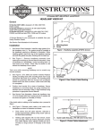
See Figure 2. Using 5/8 in. and 1/2 in. wrenches, hold the
right-side ball stud clamp (4) and loosen the jam nut (2).
10. Hold the retainer (5) with the 5/8 in. wrench, and unscrew
the ball stud clamp from the retainer. Discard the ball stud
clamp.
11. Unscrew and discard the ball stud (3) and jam nut from
the right-side turn signal (1). Remove the turn signal lamp
and allow it to hang down, taking care not to damage the
fuel tank or lamp housing.
12. Remove the retainer (5) and internal-tooth lock washer
(6) from the rear-view mirror stalk (7). Discard the lock
washer and retainer.
13. See Figure 3. Hold the left-side ball stud clamp (4) and
loosen the jam nut (2).
14. Unscrew the ball stud clamp from the ball receptacle (5).
Discard the ball stud clamp. Unscrew and discard the ball
stud (3) and jam nut from the left-side turn signal (1).
Remove the turn signal lamp and allow it to hang down,
taking care not to damage the fuel tank or lamp housing.
-J03589
1.
2.
3.
4.
5.
6.
7.
8.
9.
Left-side turn signal
Jam nut
Ball stud
Ball stud clamp
Ball receptacle
Lock washer
Rear-view mirror stalk
Acorn nut
Clutch hand lever bracket
Figure 3. Left-Side Turn Signal Removal
15. Remove the acorn nut (8), ball receptacle and internaltooth lock washer (6) from the rear-view mirror stalk (7).
Discard the ball receptacle, lock washer and acorn nut.
NOTES
FXD, FXDC and FXDL models: The turn signal wires are
routed alongside the hand-control wires through retainers fastened to the outside of the handlebar.
FXDB models: The turn signal wires are routed through
grommets on the underside of the handlebar switch housings,
then inside a sleeve along with the hand-control wires through
retainers fastened to the outside of the handlebar.
FXDWG models: The turn signal wires are routed through
grommets on the underside of the handlebar switch housings,
then inside the handlebars.
ALL models: To make removal easier, a smooth tape (such
as electrical tape) can be used to cover the socket terminals
at the ends of the turn signal wires.
16. Completely remove the turn signals and wires from the
handlebar.
2 of 5
Models with turn-signal wires OUTSIDE the handlebar
switch housings (FXD, FXDC and FXDL models): While
supporting the turn signal lamp, pull the turn signal wires
upward and outward through the wire retainers.
Set the signal lamps and wires aside for re-installation.
Models with turn-signal wires INSIDE the handlebar
switch housings (FXDB and FXDWG models):
a.
b.
c.
See the HANDLEBAR SWITCH ASSEMBLIES section
of the Service Manual. Remove one of the handlebar
switch housings from the handlebar, following the
correct (RIGHT or LEFT) HANDLEBAR SWITCH;
REMOVAL instructions. Support the hand lever so it
is not damaged,
Follow the DISASSEMBLY instructions to separate
the upper and lower switch housings. Carefully cut
the wire tie inside the switch housing, and identify the
wires coming from the turn signal lamp (not the turnsignal switch on the handlebar control pod).
While supporting the turn signal lamp, pull the turn
signal wires upward and outward through the handlebar wire harness bundle until the turn signal wires
are free of the others up to the switch housing
grommet.
d.
Remove the tape used to cover the socket terminals
at the ends of the turn signal wires. Pull the wire harness through the hole in the switch housing along
with the grommet.
e.
Remove the grommet from the turn signal wire harness, and install it back in the hole in the switch
housing. Set the signal lamp and wires aside for reinstallation.
f.
Remove the wire tie cut earlier inside the switch
housing, and re-assemble the wire bundle to the metal
bracket at the bottom of the housing using a new wire
tie from the kit. It may be necessary to use a T-15
TORX ® drive head to loosen the bracket in order to
install the wire tie.
g.
h.
Re-assemble the upper and lower switch housings
per the ASSEMBLY instructions in the Service
Manual. Install the switch housing to the handlebar
per the INSTALLATION instructions in the Manual.
Repeat for the opposite-side switch housing.
17. ALL models: See Figure 2. Obtain the acorn nut (8) and
a new lock washer (6) from the kit. Fasten the mirror stalk
to the front brake master cylinder housing (9) with the
acorn nut and lock washer, but do not fully tighten at this
time.
18. See Figure 3. Obtain the acorn nut (8) and a new lock
washer (6) from the kit. Fasten the mirror stalk to the clutch
hand lever bracket (9) with the acorn nut and lock washer,
but do not fully tighten at this time.
19. See Figure 4. Obtain the turn signal stalks from the kit.
The left-side (1) and right-side (2) stalks can be identified
by the part numbers found at the wide end, or by positioning the stalk, with the wire notch (A) at the bottom,
against the mounting location on the lower fork bracket.
NOTES
Both left-side and right-side turn signal lamps are identical.
-J03589
The wire harness coming from the turn-signal lamp has a flat
cross-section, similar to the wire slot (B) near the lamp end of
the stalk.
For best appearance, align the harness along its full length to
determine the flat side that will lie against the stalk when the
lamp is attached. Insert the harness into the slot in that orientation to avoid a half-twist in the wire harness at the lamp.
20. Carefully feed the length of wire from the turn-signal lamp
into the stalk through the wire slot (B) near the lamp end.
21. Obtain a socket head cap screw (3) and split lock washer
(4) from the kit. Place the lock washer onto the screw
threads, and insert the screw into the deep recess in the
stalk and through the hole. Position the turn-signal lamp
against the end of the stalk, and thread the screw into the
lamp housing.
22. Place the assembled stalk and lamp in the mounting
position on the lower fork bracket (C), and align the lamp
to face forward, and parallel to the ground. While holding
the alignment, remove the assembly and tighten the lamp
mounting screw to 72-84 in-lbs (8.1-9.5 Nm).
23. Verify that the front suspension is unloaded (front wheel
raised slightly off the ground), then remove and discard
the pinch screw (D) from the lower fork bracket.
24. Fasten the stalk assembly to the lower fork bracket with
a new, longer pinch screw (5) from the kit, taking notice
of the following:
a.
This is a thread-cutting screw and can be prone to
cross-threading if not careful! Finger-tighten the first
few threads as far as possible to feel for and avoid
cross-threading.
b.
With the stalk centered relative to the fork bracket,
verify that the lamp is facing forward and parallel to
the ground. If not, repeat step 22.
c.
Verify that the stalk wire notch is facing downward. If
not, switch this assembly to the other side of the
vehicle, and repeat steps 19 to 24b with the remaining
lamp and kit items.
d.
Verify that the exiting wire is centered in the wirenotch at the stalk base and is not being pinched by
the stalk against the fork bracket.
25. With the stalk centered on the fork bracket, all orientations
correct AND the exiting wire centered in the stalk wire
notch, torque the pinch bolt to 30-35 ft-lbs (40.7-47.5 Nm).
26. Repeat the lamp and stalk installation for the opposite side
of the vehicle.
27. Remove the cap screw and washer (E) that mount the
front brake line(s) to the underside of the lower fork
bracket, and set it aside.
28. Obtain the "P"-clamp (6) from the kit, and loosely install it
with the cap screw removed from the previous step. Insert
the screw through the new "P"-clamp and the brake line
mounting to the underside of the fork bracket.
NOTE
"P"-clamp orientation should be opposite of the brake-line
mounting.
29. See Figure 4. Route the wires behind the fork tubes. Feed
both signal wires through the new "P"-clamp in the direc3 of 5
tion (F) opposite that from which they originated, so the
wire is heading back toward its own turn signal lamp.
Pull the wires through the "P"-clamp so they are just pulled
taut, and torque the cap screw to 8.3-10.0 ft-lbs (11.3-13.6
Nm).
The wires from the right-side turn signal should now be
toward the right side of the vehicle, and the left-side wires
toward the left.
30. Obtain the white (left, item G) and black (right, item H) 3place turn signal connectors removed from the turn signal
harnesses earlier.
31. Refer to the AMP MULTILOCK ELECTRICAL CONNECTORS section of the Service Manual to install the socket
terminals from the the turn signal harnesses into the correct lamp-side connector halves. Unless noted differently
on removal,
a.
install the Black wire into cavity 1,
b.
the Violet wire to cavity 2, and
c.
the Blue wire (if installed) to cavity 3
32. See Figure 1. Feed the assembled right-side (black) turnsignal connector, from the outside, through the grommet
(4) in the right side of the frame, behind the steering head.
Feed the assembled left-side (white) connector through
the grommet in the left side of the frame.
33. Re-connect the left and right connector halves to the samecolor mating connector halves coming from the frame.
36. Use wire ties from the kit as needed to secure the harnesses so they do not interfere with steering function, or
become entangled or pinched.Wire tie any excess harness
length so it can be stowed inside the steering head.
37. Push the wire harness back up inside the frame, behind
the steering head. Position the harness shield (1) to the
underside of the top bar with the tabs (2) inside, and push
upward until the tabs engage the holes (3) on each side
of the frame.
To prevent accidental vehicle start-up, which could cause
death or serious injury, remove maxi-fuse before proceeding. (00251a)
When servicing the fuel system, do not smoke or allow
open flame or sparks in the vicinity. Gasoline is extremely
flammable and highly explosive, which could result in
death or serious injury. (00330a)
38. See FUEL TANK: INSTALLATION in the Service Manual.
Follow the steps to re-install the fuel tank and re-connect
the fuel line.
39. Refer to the Service Manual and follow the instructions
given to re-install the maxi-fuse.
40. Follow the instructions in the Service Manual to re-install
the seat.
34. Refer to the Service Manual and follow the instructions
given to temporarily re-install the maxi-fuse.
35. Test the turn signals to ensure they function correctly.
Be sure that steering is smooth and free without interference. Interference with steering could result in loss of
vehicle control and death or serious injury. (00371a)
•
Be sure wires do not pull tight when handlebars are
turned fully to left or right fork stops.
-J03589
After installing seat, pull upward on seat to be sure it is
locked in position. While riding, a loose seat can shift
causing loss of control, which could result in death or
serious injury. (00070b)
41. Adjust the mirrors for proper field of vision and tighten the
acorn nuts to 12 ft-lbs (16 Nm). Check mirror adjustment
and reposition if necessary.
4 of 5
SERVICE PARTS
is00698a
5
B
7
4
68538-06
H
F
G
1
A
3
8
8
D
9
C
9
5
6
2
E
Figure 4. Service Parts, Front Turn Signal Relocation Kit
Table 1. Service Parts Table
Item
Description (Quantity)
Part Number
1
Stalk, front turn-signal relocation (left)
68538-06
2
Stalk, front turn-signal relocation (right)
68697-06
3
Socket head cap screw, 5-16-24 x 5/8 in., Grade 8 (2)
2698A
4
Lock washer, split, 5/16 in. (2)
7042
5
Button head self-tapping screw, 3/8-16 x 2-1/4 in., Grade 8 (2)
4047
6
"P"-clamp, 5/16 in., cushioned
10059A
7
Wire tie (8)
10065
8
Lock washer, internal tooth, 5/16 in. (2)
7127
9
Acorn nut, tall, 5/16-24, chrome (2)
7720
Items mentioned in text, but not included in kit:
A
Wire notch
B
Wire slot
C
Lower fork bracket
D
Original equipment pinch screw (2)
E
Brake line retaining cap screw and washer
F
Feed turn-signal wires through "P"-clamp as shown
G
White 3-place left-turn signal connector
H
Black 3-place right-turn signal connector
-J03589
5 of 5