1
Body Builders Layout Book
4
PART II (Cont’d)
5.
These instructions must be followed in the vehicle
alteration:
•
The following components, as installed by Ford
Motor Company, are not to be removed, relocated,
altered, or modified in any way:
Example
A vehicle alterer wants to remove the pickup box and
rear step bumper from a Super Duty F-250 Regular Cab
(4x4), 137-inch WB model with a 5.4L engine, automatic
transmission, and air conditioning having a curb weight
of 6200 lb and install a 600-pound Second Unit Body
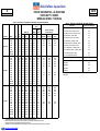
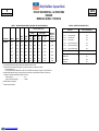
(SUB). First, Table A (on page 7 ) specifies that the
maximum SUB weight is 1800 lb. Since the SUB weight
is 600 lb, this condition is satisfied.
Second, the SUB weight must not exceed the SUB
WEIGHT LIMIT calculated below:
SUB WEIGHT LIMIT = Maximum Complete Unloaded
Vehicle Weight (UVW) minus
the unloaded vehicle weight as
delivered (OEM) curb weight
plus pickup box weight removed
plus weight of removed options.
SUB WEIGHT LIMIT = 6900 – 6200 + 380 + 74
SUB WEIGHT LIMIT = 1154 lb
The 600 lb SUB is less than 1154 lb and, accordingly,
may appropriately be installed as planned.
The vehicle alterer must either select a lighter weight
SUB, reduce the OEM accessory weights for the vehicle,
or both if the SUB is heavier than the maximum limit.
1.
OEM Curb Weight includes Base Vehicle Weight
(with full fuel), engine and transmission weight, and
all OEM accessory weights ordered or installed
(Refer to the appropriate Truck Source Book or the
CD version of this publication for weight data).
2.
Options removed include step bumpers or similar
OEM options permanently removed from the
vehicle.
3.
The center of gravity height and overall height of the
second unit body installed by the alterer must not
exceed the values specified in Table A, pages 361362 corresponding to the particular pickup model.
Center of gravity height and overall height of the
second unit body are measured from the top surface
of the frame at the rear of the cab.
4.
The altered vehicle’s unloaded vehicle weight (see
Definitions in Safety/Emission section) must not
exceed the values designated in Table A pages 361362 corresponding to the pickup truck’s model and
non-California engine-transmission combination.
2010
PICKUP BOX REMOVAL / ALTERATIONS
DESIGN RECOMMENDATIONS (Cont'd)
PICKUP BOX REMOVAL
•
– Steering column, steering shaft, steering wheel,
and related structural
components and
attachment hardware
– Windshield and windshield mounting system
positions (as defined in F/CMVSS No. 208)(2); any
additional loss of windshield retention (as defined in
F/CMVSS No 212)(3); any change in the
performance requirements of F/CMVSS 214(3)(4);
any penetration of the inner surface of the
windshield or intrusion into the protected zone (as
defined in F/CMVSS No. 219)(3); or loss of fuel
system integrity (as defined in F/CMVSS No.
301)(3); when the vehicle is tested in any manner
specified by applicable provisions of F/CMVSS Nos.
105(5), 135(5), 204(1), 208(2), 212(3), 214(3(4), 219(3),
and 301(3), respectively.
– Cab and front end structural components,
including
the
roof, pillars,
cowl,
cowl
reinforcements, hood, doors, fenders, hood
restrictors and apron reinforcements, and frame
and frame reinforcements
– Radio antenna
– Doors and hood mounting, hinging, and latching
systems
– Hood and fender ornamentation
– Fuel tank and attachment hardware, including
sending unit and vapor valve, fuel tank shield, and
in-tank electric fuel pump (for gasoline engine
only)
– Fuel lines, routing, and attachments, excluding
fuel filler cap, filler pipe, filler hose(s), and filler
system attachment hardware, which must be
removed and replaced
– Vapor line(s) and carbon canister(s)
– Fuel pump
– Fuel filter and attachment
– Air cleaner assembly
– Safety belts
– Front seat head restraints
– Electrical grounds on all components (must be
retained)
– The Powertrain Control Module (PCM), and
– Catalyst and Exhaust System.
Any alteration or modification made to the vehicle,
as manufactured by Ford Motor Company, and any
components or structure installed by the vehicle
alterer must not result in steering column rearward
displacement of more than 5 inches (as defined in
F/CMVSS No. 204)(1); no modification to the
Hydraulic Brake System that would affect
compliance to F/CMVSS No 105 or 135(5); an
increase in injury potential for front outboard seating
NOTE: Federal Motor Vehicle Safety Standard (FMVSS)
and Canadian Motor Vehicle Safety Standard (CMVSS)
No 204 are not applicable to a vehicle with an unloaded
vehicle weight greater than 5500 lb. F/CMVSS No. 208
injury criteria are applicable only to vehicles with a
GVWR of 8500 lb or less and an unloaded vehicle
weight of 5500 lb or less. Conformity to Federal Motor
Vehicle Safety Standard (FMVSS) and Canadian Motor
Vehicle Safety Standard (CMVSS) No. 212 and 219 for
vehicles having a gross vehicle weight rating (as defined
in 49 CFR, Part 571.3) no greater than 10,000 lb, is
established for representative vehicles at a vehicle
weight provided by Sections S6.1(b) and S7.7(b) of
FMVSS No. 212 and 219, respectively, and provided by
Sections 5.1 and 8 of CMVSS No. 212 and 219,
respectively.
•
– Trailer hitch receiver
•
The second unit body installed shall be mounted
securely and so designed that when the altered
vehicle is impacted in any manner specified by
applicable provisions of F/CMVSS No. 212(3) and
219(3), second unit body deformation or movement
relative to the frame does not result in any
separation or loss of body attachment to the frame.
The second unit body installed and the required fuel
system components (identified below) shall be
located and mounted as follows:
MODEL YEAR
– The second unit body shall be mounted securely
and is so designed that when the altered vehicle
is tested in any manner specified by applicable
provisions of F/CMVSS No. 301(3):
(a) Second unit body components shall not
contact any fuel system component (other
than at the points where the fuel system is
permanently attached to the second unit
body) and
(b) Second unit body deformation or movement
relative to the frame shall not cause any fuel
system component to be penetrated,
disconnected, or otherwise damaged.
– The rear end of the second unit body (excluding
the rear bumper) installed shall not extend
beyond (overhang) the rear edge of the vehicle
frame or frame extension. Any extension of the
vehicle frame must be constructed and attached
so as to perform as a continuation of the vehicle
frame when the altered vehicle is tested in any
manner specified by applicable provisions of F/
CMVSS No. 301(3).
– See the Design Recommendations, Second Unit
Body (SUB) attachment section of this book
for additional information.
– The fuel filler cap, filler pipe, filler hose(s), and
filler system attachment hardware for vehicles
with diesel engines and for vehicles with gas
engines shall be installed, as shown in the Super
Duty F-Series section and shall be securely
retained to remain intact when the vehicle is
tested in any manner specified by applicable
provisions of F/CMVSS No. 301(3).
NOTES —
(1) For vehicles with a GVWR of 10,000 lb or less and an
unloaded vehicle weight of 5500 lb or less.
(2) Injury criteria is applicable to vehicles with a GVWR of
8500 lb or less and an unloaded vehicle weight of 5500
lb or less.
(3) Applicable to vehicles with a GVWR of 10,000 lb or less.
(4) Dynamic Performance Requirements apply to MPV,
Truck, or a Bus with a GVWR of 2722 Kg (6000lb) or
less for FMVSS only.
(5) Standard 135 applied to vehicles with a GVWR of 3500
Kg (7716 lb) or less. Standard 105 applies to vehicles
with a GVWR over 3500 Kg (7716 lb).
(Cont'd next page)
www.fleet.ford.com/truckbbas