1
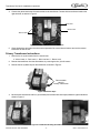
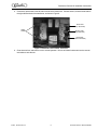
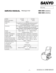
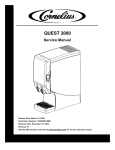
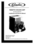
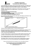
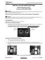
Transformer Service Kit Installation Instructions INSTALLATION INSTRUCTIONS TRANSFORMER SERVICE KIT CORNELIUS P/N 620710739S ! WARNING: Disconnect power to the unit before servicing. Follow all lock out/tag out procedures established by the user. Verify all power is off to the unit before performing any work. Failure to comply could result in serious injury, death or damage to the equipment. ! CAUTION: Before replacing the Secondary Transformer on a Viper unit be sure to read and understand all safety labels, and safety warnings on the machine and safety warnings in owners and service manuals. Tools Required: Phillips screw driver - Needle-nose pliers - 5/16” Nut driver Perform the following procedure: 1. Open the electrical box, and locate the transformer to be replaced (shown in Figure 1). The transformers are located in the upper left hand corner of the electrical box. If the secondary transformer needs to be replaced, follow the Secondary Transfomer Instructions. If the primary transformer needs to be replaced, follow the Primary Transformer Instructions. Secondary Transformer Primary Transformer Figure 1. Transformer Locations Secondary Transformer Instructions 1. Remove the four (4) wire leads from the transformer: 2- Yellow Leads, 1- Blue Lead and 1 - Brown Lead 2. Remove the transformer from the electrical box by removing the four (4) 8-32 screws holding it in place. 3. Mount the new transformer with four (4) terminals (two terminals with black caps) toward the right side as shown in Figure 2. Figure 2. Transformer Mounting Orientation Release Date: March1, 2011 © 2011, IMI Cornelius Inc. www.cornelius.com -1- Revision: A Publication Number: 620710739SINS Transformer Service Kit Installation Instructions 4. Connect the yellow lead to the left hand terminal on the transformer. Connect the blue and brown leads to the right terminals, as shown in Figure 3. Blue Lead Brown Lead Yellow Leads Figure 3. Transformer Lead Location and Colors 5. Close electrical box and return the unit to normal operation. Be sure to follow all owners and service manual instructions to start the unit. Primary Transformer Instructions 1. Remove the six (6) wire leads from the transformer: 2- Yellow Leads, 2 - Red Leads, 1- Blue Lead and 1 - Brown Lead 2. Remove the transformer from the electrical box, by removing the four (4) 8-32 screws. 3. Remove the two (2) black caps on the transformer, as shown in Figure 4. Remove black caps for Primary Transformer Figure 4. Protective Caps 4. Mount the new transformer with four (4) terminals (two terminals with black caps) toward the right hand side as shown in Figure 5. Figure 5. Transformer Mounting Orientation Publication Number: 620710739SINS -2- © 2011, IMI Cornelius Inc. Transformer Service Kit Installation Instructions 5. Connect the yellow leads to the left side terminals on the transformer. Connect the blue, brown and red leads to the right side terminals of the transformer, as shown in Figure 6. Blue Lead (Top Terminals) Yellow Leads Brown Lead (Top Terminals) Red Leads (Bottom Terminals) Figure 6. Transformer Lead Location and Colors 6. Close electrical box, and return the unit to normal operation. Be sure to follow all owners and service manual instructions to start the unit. © 2011, IMI Cornelius Inc. -3- Publication Number: 620710739SINS