1
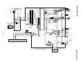
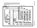
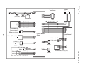
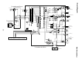
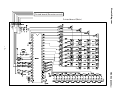
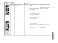
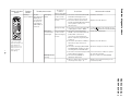
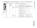
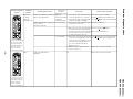
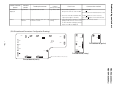
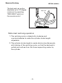
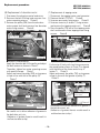
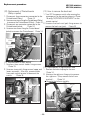
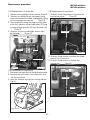
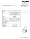
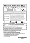
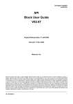
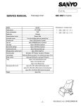
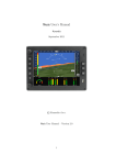
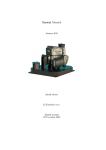
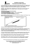
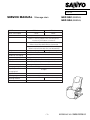
FILE No.
SERVICE MANUAL Massage chair
HEC-902 (GENERAL)
HEC-904 (GENERAL)
MODEL
Power consumption
Rated time
Timer
Dimension
Weight
Exterior cloth
Number of massagings
Number of tappings
Tapping width
HEC-902
HEC-904
90 W
130 W
30 min
[manual]about 15 minutes,[automatic]neck / shoulder
about 11 minutes,[upper half of the body]about
13 minutes,[waist]about 13 minutes.
660 mm(width) X 1,000 mm(depth) X 1,030 mm(height)
*When not reclined(with foot rest retracted)
660 mm(width) X 1,650 mm(depth) X 570 mm(height)
*When reclined (with foot rest set horizontally)
Approx. 50 kg
Approx. 52 kg
Polyester chloride 100 %
3 stages 20 times/min., 25 times/min., 30 times/min.
3 stages 360 times/min., 480 times/min., 600 times/min.
3 stages Approx. 70 mm, 100 mm, 130 mm
Vertical movement speed
One reciprocating motion in approx. 27 sec.
Backborn stretching width
3 stages Approx. 70 mm, 100 mm, 130 mm
Massaging ball up/down range
Approx. 600 mm
Height adjustment of
3 stages
massaging ball.
Leg vibration
Reclining angIe
Reclining method
Accessory
Vibration type
Approx. 120~170
Manual method
Motor-driven type
Head cover
- 1-
REFERENCE NO. SM6510035-00
CN10
Switch
Transfomer
CN201
CN13
Printed board
(Main)
Printed board
(Relay)
CN203
Limit switch
CN14
CN4
Condenser
(10 F 250V)
CN3
Motor (Elevation)
CN2
- 2-
Motor (Leg vibrator)
CN6 CN8
CN11
CN101
Printed board
(Remote control)
CN9
CN1
Fuse
(250V 3.15A)
(Massage)
Transfomer
Wiring Diagram
Motor
Limit switch
CN301
CN202
Reactor
HEC-902 (GENERAL)
CN7
Printed board (Massage pulse)
Reactor
Reactor
Limit switch
Motor (Tapping)
Reactor
Circuit Diagram
Printed board (Relay)
Motor (Massaging)
IC 202
Massaging pulse
Printed board
(Pulse)
Tapping pulse
IC 301
Condenser
( 10 F 250 V )
Reclining motor
- 3Motor (Leg vibrator)
Fuse
Switch
( 250 V 3.15 A )
Printed board (Remote control)
Transfomer
HEC-902 (GENERAL)
Printed board (Main)
RESET
SO
SI
SCLK
5V
GND
Printed board (Main)
Circuit Diagram
Printed board (Remote control)
- 4HEC-902 (GENERAL)
CN10
Switch
Transfomer
Printed board
(Main)
Printed board
(Relay)
Limit switch
CN301
Reclining motor
CN7
Reactor
HEC-904 (GENERAL)
Switch
Printed board (Massage pulse)
CN12
Switch
CN5
Motor
CN202
Reactor
CN203
Limit switch
CN14
CN4
Condenser
(10 F 250V)
CN201
CN3
Motor (Elevation)
CN13
CN2
- 5-
Motor (Leg vibrator)
CN6 CN8
CN11
CN101
Printed board
(Remote control)
CN9
CN1
Fuse
(250V 3.15A)
(Massage)
Wiring Diagram
Motor
Transfomer
Reactor
Limit switch
Limit switch
Motor (Tapping)
Reactor
Circuit Diagram
Printed board (Relay)
Motor (Massaging)
IC 202
Massaging pulse
Reclining motor
Printed board
(Pulse)
Tapping pulse
IC 301
Condenser
( 10 F 250 V )
-6-
Reclining motor
Motor (Leg vibrator)
Fuse
Switch
( 250 V 3.15 A )
Printed board (Remote control)
Transfomer
HEC-904 (GENERAL)
Printed board (Main)
RESET
SO
SI
SCLK
5V
GND
Printed board (Main)
Circuit Diagram
Printed board (Remote control)
- 7HEC-904 (GENERAL)
Troubled
portion
Trouble phenomenon
Power and
Nothing is displayed after the
remote control power ON.
relations
Nothing is displayed
-8-
Remote control Trouble described left is
relations
displayed immediately or 3
seconds after the power switch
is turned ON.
3. Check Printed board (Main) CN9
output (AC100V).
4. Check power transformer output
CN10 (approx. 12V).
5. Check Printed board (main) CN11 and
Printed board (remote control) CN101
for connector come-off.
Check pins (both No.5 (brown) and
No.7 (black), or No.1 (white) and
No.2 (red) for come-off.)
6. Check the remote control cable for
disconnection or shorting.
(both brown and black wires or
white and red wires)
7. When no fault is detected upon
checking in Step 1 - 6;
Immediately or 3 1. Check the Printed board (main) CN11
and Printed board (remote control)
seconds later
CN101 connector pins for
come-off. (Pin No. 3 (blue), 4
(yellow), and 6 (orange)
2. Check the remote control cable for
disconnection or shorting.
(Blue, yellow and orange wires)
3. When no fault is detected upon
above check;
Counteraction method
Replace the current fuse (3.15A).
Check the power switch and power cord
and transfomer for normal conductivity and
replace them if necessary upon check.
Replace the Printed board (main).
Replace the power transformer.
Insert the connector and pins.
Replace the remote control cable.
Replace the Printed board (remote control)
or Printed board (main).
Insert the connector pins.
Replace the remote control cable.
Replace the Printed board (remote control)
or Printed board (main).
HEC-902 (GENERAL)
HEC-904 (GENERAL)
The power lamp,and
massage red lamp,
tapping red lamps,
stretch 1 red lamps,
stretch 2 red lamps,
combi red lamps lighting.
Occurrence
condition
Check item
(after power "ON")
Immediate
1. Check current fuse (3.15A) for
fusion.
2. Check Printed board (Main) CN1
output (AC100V).
Problem diagnosis chart
Trouble indication
pattern
Troubled
portion
Trouble phenomenon
Counteraction method
Insert the connector.
Replace the main harness
If output Replace the massage motor.
If no output Replace the Printed board (main).
Insert each lead wire pin.
Problem diagnosis chart
Occurrence
condition
Check item
(after power "ON")
Massage
Trouble
Massaging
15 seconds later 1. Check the Printed board (main) CN6
motor relations described left is failure
or 15 seconds
and CN7 and massage motor
displayed 15
after massaging
junction connector for come-off.
seconds after
motion
2. Check the harness between the
the power is
Printed board (main) CN6 and massage
turned ON or
motor junction connector for
"MASSAGE" is
disconnection.
selected.
during massage 3. Check the Printed board (main) CN6
output (approx. DC57 - 100V).
Massaging
15 seconds later 4. Check the Printed board (relay)
CN201 connector and Printed board
mode remains or 15 seconds
(main) CN13 connector for
unchanged.
after massaging
come-off of each lead wire pin
motion
(Pin No. 3 (brown), 4 (yellow) and
7 (white).)
The power lamp, the
5. Check the main harness CN201 to
center of the width
CN13 line for disconnection or
lamp and massage red
shorting.
lamp, tapping red
lamps, stretch 1 red
6. Check the massaging "POSITION"
lamps, stretch 2 red
and "ROTATION" magnets for their
lamps, combi red
mounting direction and fall-down.
lamps lighting.
7. Check the Printed board (relay) IC 201
and IC 202 for inclination.
Massage motor
8. Check the belt (MOMI) for
running
dislocation and cut-off.
9. When no fault is detected upon
checking in the Step 1 - 8;
Trouble indication
pattern
Replace the main harness
Mount the magnet in normal condition.
- 9-
Correct the tilted condition or replace
the Printed board (relay).
Mount or replace the belt (MOMI).
Replace the Printed board (relay) or the
Printed board (main).
HEC-902 (GENERAL)
HEC-904 (GENERAL)
Troubled
portion
Trouble phenomenon
Tapping motor Trouble
Tapping failure
described left is
relations
displayed 15
seconds after
the power is
turned ON or
"TAPPING" is
selected.
Tapping mode
remains
unchanged.
- 10-
The power lamp, the
center of the width
lamp and massage red
lamp, tapping red
lamps, stretch 1 red
lamps, stretch 2 red
lamps, combi red
lamps lighting.
Tapping motor
running
Occurrence
condition
Check item
(after power "ON")
15 seconds later 1. Check the Printed board (main) CN8
and CN14 and the tapping motor
or 15 seconds
junction connector for come-off.
after tapping
2. Check the Printed board (main) CN8
motion
to tapping motor connector harness
for disconnection.
during tapping
3. Check the Printed board (main) CN8
output (approx. DC57 100V).
15 seconds after 4. Check the Printed board (relay)
CN202 connector for come-off and
tapping motion
pins for come-off.
5. Check the Printed board (pulse)
CN301 connector for come-off and
pins for come-off.
6. Check the Printed board (relay)
CN201 and Printed board (main) CN13
connectors for come-off of each
lead wire pin (No.2).
7. Check the junction harness (CN202
- CN301 circuit) for disconnection
or shorting.
8. Check the tapping magnet for its
mounting direction and fall-down.
9. Check the Printed board (pulse)
IC 301 for inclination.
10. Check the belt (TATAKI) for
dislocation and cut-off.
11. When no fault is detected upon
check in Step 1 - Step 10;
Counteraction method
Insert the connector.
Replace the main harness
If output Replace The tapping motor.
If no output Replace the Printed board (main).
Insert the connector and pins.
Insert the connector and pins.
Problem diagnosis chart
Trouble indication
pattern
Insert each lead wire pin.
Replace the junction harness
Mount the magnet in normal condition.
Correct the tilted condition or replace
the Printed board (pulse).
Mount or replace the belt (TATAKI).
Replace the Printed board (relay or pulse)
or the Printed board (main).
HEC-902 (GENERAL)
HEC-904 (GENERAL)
Troubled
portion
Trouble phenomenon
Counteraction method
Insert the connector and pins.
If output from the both
Replace the elevation motor.
If either or neither from the both
Replace the Printed board (main).
Problem diagnosis chart
Occurrence
condition
Check item
(after power "ON")
Elevation
Elevation failure
During elevation 1. Check the Printed board (main) CN3
motor relations
or 30 seconds
and CN4 connectors for come-off
later
and pins for come-off.
2. Pull out CN3 on the Printed board
(main) and check for the red pin to
white pin output and blue pin to
white pin output of the Printed board
side CN3 (to be approx. AC100V
respectively).
*For checking, turn ON the
massager from the remote control
and keep either vertical adjust
button "UP" or "DOWN" as pressed.
3 seconds later
3. Check the Printed board (relay)
Trouble described left is
CN201 connector for come-off.
displayed 3 seconds after the
The power lamp, the
4. Check the Printed board (relay)
power is turned ON.
center of the speed
CN203 connector for come-off.
(The upward motion is effected
lamp, and massage red
immediately
only
after
the
power
5.
Check the Printed board (main) CN13
lamp, tapping red
connector for come-off.
is turned ON.)
lamps, stretch 1 red
lamps, stretch 2 red
6. Check the Printed board (relay)
lamps, combi red
CN201 connector and Printed board
lamps lighting.
(main) CN13 connector for
come-off of each lead wire pin
thereof (both No.1 (black) and No.6
(red), or No.5 (blue).
7. Check the main harness (CN201 to
CN13) for disconnection or shorting.
(No.1 (black), No.6 (red) and No.5
(blue) )
Trouble indication
pattern
Insert the connector.
Insert the connector.
Insert the connector.
Insert each lead wire pin.
- 11 -
Replace the main harness.
HEC-902 (GENERAL)
HEC-904 (GENERAL)
Troubled
portion
Trouble phenomenon
Elevation
Trouble described left is
motor relations displayed 3 seconds after the
power is turned ON or after
starting elevation.
(Start elevation.)
Occurrence
condition
Check item
(after power "ON")
3 seconds later or 8. Check the upper and lower limit
30 seconds after
switches for trouble
elevation
(micro switch and harness).
< Under normal condition >
1. Stop at the highest position
Counteraction method
Replace the connector ass'y (upper and
lower limit switches).
(upper limit switch ON, lower limit switch OFF)
Pin 1 - 2 (white - red) of CN203 connector
(open)
Pin 3 - 4 (green - yellow) of CN203
0
(close)
2. Stop at the middle position.
Problem diagnosis chart
Trouble indication
pattern
(Upper limit switch OFF, lower limit switch OFF)
Pin 1 - 2 (white - red) of CN203 connector
- 12-
The power lamp, the
center of the speed
lamp, and massage
red lamp, tapping red
lamps, stretch 1 red
lamps, stretch 2 red
lamps, combi red
lamps lighting.
0
(close)
Pin 3 - 4 (green - yellow) of CN203
0
(close)
3. Stop at the lowest position.
(Upper limit switch OFF, lower limit switch ON)
Pin 1 - 2 (white - red) of CN203 connector
0
(close)
Pin 3 - 4 (green - yellow) of CN203 connector
(open)
30 seconds after 9. Check the elevation magnet for the Mount the magnet in normal condition.
When "STRETCH 2" mode is
mounting direction and fall-down.
selected, "STRETCH 1" motion is elevation
10. Check the Printed board (main) IC4 Correct the tilted condition or replace the
effected and trouble described
left is displayed.
for tilt.
Printed board (main).
Trouble described left is displayed
11. Check the belt (ROLLING) for
Mount or replace the belt (ROLLING).
with no elevating motion. (The
dislocation and cut-off.
elevation motor running)
12. When no fault is detected upon Replace the Printed board (relay or pulse)
check in Step 1 ~ 11;
or the Printed board (main).
HEC-902 (GENERAL)
HEC-904 (GENERAL)
Troubled
portion
Trouble phenomenon
Problem diagnosis chart
Occurrence
condition
Check item
Counteraction method
(after power "ON")
1. Check the Printed board (main) CN5 Insert the connector and pins.
Trouble described left is displayed When the
Motorized
with no reclining motion.
motorized reclining connector and pins for come-off. If output, Replace the reclining motor.
reclining
operation is
relations
2. Check the Printed board (main) CN5 If no output Replace the Printed board (main).
effected normally;
(HEC-904 only)
output (to be approx. DC90V).
Trouble described left is displayed 3 seconds later
3. Check the Printed board (main) CN12 Insert the connector.
connector for come-off.
three minutes
after the power ON.
4. Pull out the Printed board (main) CN12 When the both are
(open);
connector and check whether the
current is across No.1 to No.2 pin and Replace the reclining motor.
No.3 to No.4 pin of the motorized
recliner side CN12 connector.
3 seconds later
5. Pull out the Printed board (main) CN5 occur Replace the Printed board (main).
connector for shorting No.1 to No.2 No occur Replace the reclining motor.
The power lamp, the
circuit of CN12. Turn ON the power
center of the speed lamp,
switch after shorting Pin No. 3 to
the center of the width
4, to check whether trouble is
lamp and massage red
displayed or not.
lamp, tapping red lamps,
stretch 1 red lamps,
6. When no fault is detected upon
Replace the Printed board (main).
stretch 2 red lamps,
check in Step 1 - 5;
Trouble indication
pattern
- 13 -
combi red lamps lighting.
Other
No
Replace the Printed board (main).
HEC-902 (GENERAL)
HEC-904 (GENERAL)
The power lamp, the
both edges of the speed
lamp, and massage red
lamp, tapping red lamps,
stretch 1 red lamps,
stretch 2 red lamps,
combi red lamps lighting.
Trouble described left is
displayed.
No trouble is
displayed.
Leg vibrator
Trouble phenomenon
Leg vibrator fails to start.
Occurrence
condition
Check item
Counteraction method
(after power "ON")
Leg vibrator "ON" 1. Check that Leg vibrator.
If the lamp OFF
lamp on the remote control is ON.
Check and replace the Printed board (remote control).
Various
Remote control Trouble is displayed (motion stop) Each function in
relations
from time to time.
running
2. Check the Printed board (main) CN2 If output Replace the cushion (footrest).
If no output Replace the Printed board (main).
output (to be approx. DC12V).
1. Start massaging in "AUTO" mod and Replace the remote control.
lightly pull the remote control cord
to check whether massaging motion
stops or trouble is displayed.
Problem diagnosis chart
Troubled
portion
Trouble indication
pattern
( ON-Printed-board Connectors Configuration Drawing )
CN9
CN5
CN6
CN8
CN3
3
2
1
1
2
3
IC202
CN202
IC301
1
2
3
CN30
CN7
- 14-
CN1
CN14
CN4
IC201
CN2
CN201
CN10
Printed board (pulse)
CN203
IC4
4
3
2
1
1
2
3
4
5
6
7
4 3 2 1
Printed board (relay)
CN12
CN13
7 6 5 4 3 2 1
CN11
7 6 5 4 3 2 1
CN5 and CN12 available for HEC-904 only.
Printed board (main)
HEC-902 (GENERAL)
HEC-904 (GENERAL)
Motorized Reclining
HEC-904 (GENERAL)
The back rest can recline
steplessly up to 170 degree
maximum by operating
"RECLINING" switch on
the remote control.
Back rest
Motorized reclining operation
1. The reclining motor rotates both clockwise and
counterclockwise to make the cylinder stroke length
adjustable.
2. The cylinder stroke length is made shorter simultaneously
with startup of the reclining motor, so that the backrest is
pulled and reclines from the frame supporting center by
the cylinder.
- 15 -
Massage motors
HEC-902 (GENERAL)
HEC-904 (GENERAL)
2
2
1
2, Massage motor
3
1, Tapping motor
Screw bar
3, Elevation motor
1, Tapping motor
This motor rotates to move the massage balls upward and downward alternately via
the driving belt coupled to the motor.
(The motor revolutions is adjustable in three steps so that the patting frequency
can be changed over to approximately 360, 480 and 600 cycles/minute.)
2, Massage motor
This motor rotates to move the massage balls crosswise via the driving belt and gear
box coupled to the motor.
(The motor revolutions is adjustable in three steps so that the massaging frequency
can be changed over to approximately 20, 25 and 30 cycles/minute.)
(When patting and stretching the backbone line, the massage ball position (ball
moving range) can be changed over in three steps after starting the patting motor.)
3, Elevation motor
This motor rotates to transmit its rotating torque to the threaded rod via the driving
belt, whereby the massage unit is moved upward and downward.
(This motor rotates clockwise and counterclockwise to thereby move the massage
unit upward and downward.)
Tapping-massaging
You can enjoy the good comfort that you can not do by hand tapping-massage, by
starting both the tapping motor and the massage motor simultaneously.
I-shaped tapping - Z-shaped massaging
Massaging same portion can be prevented by moving minutely the massage balls
upward and downward by starting the elevation motor while running the tapping
motor for tapping operation or the massage motor for massaging operation.
- 16-
Replacement procedure
HEC-902 (GENERAL)
HEC-904 (GENERAL)
(1) How to remove the rear cover
(3) Replacement of power switch
1. Unscrew four fixing screws to remove the rear
cover. Fig.1
1. Unscrew two case fixing screws to remove the
power switch. Photo.4
* In removing, shift the switch in arrow direction
from the bushing of the remote control cord.
Remote control
Rear cover
Bushing of the
remote control cord
Power switch
Screws
Screws
Fig.1
(2) Replacement of the printed board (main)
Photo.4
1. Unscrew three fixing screws to remove the cover
(the printed board, main). Photo.2
2. Open the power fuse case to take out the fuse.
Photo.5
3. Unscrew two switch holder fixing screws to
Screws
remove the power switch. Photo.5
4. Pull out the auxiliary connector outward, which
is fitted in the case (power switch). Photo.5
Screws
Fuse
Cover(Printed board, main)
Photo.2
Power switch
2. Pull out 14 connectors (12 in the case of
HEC-902) which are connected to the printed
board (main) and thereafter demount the
printed board. Photo.3
3. Unscrew two transformer fixing screws to
remove the transformer. Photo.3
4. Unscrew two reactor fixing screws and one
capacitor fixing screw. Photo.3
Transfomer
Screw
Printed board(main)
Screw
Reactor
Condenser
Photo.3
Connector
Cord bushing
Photo.5
(4) Replacement of power cord
1. Disconnect the power cord connector to remove
the cord bushing from the power cord. Photo.5
(5) Replacement of remote control
1. Remove the bushing from the remote cord.
Photo.4
2. Unscrew four remote control case fixing screws
to open the case. Fig.1
3. Unscrew two printed board (remote control)
fixing screws to disconnect the remote control
cord connector.
- 17 -
Replacement procedure
HEC-902 (GENERAL)
HEC-904 (GENERAL)
(6) Replacement of elevation motor
1. Disconnect the elevation motor lead wires.
2. Remove the belt (Rolling) and unscrew four
motor mounting screws. Photo.6
3. Remove the pulley (SM) from the elevation
motor output shaft and unscrew four elevation
motor fixing screws. Photo.6
Elevation motor
(7) Replacement of tapping motor
1. Disconnect the tapping motor cord connector.
2. Remove the belt (TATAKI). Photo.8
3. Unscrew one motor fixing screw. Photo.8
4. Unscrew two stay A (motor T) fixing screws
and remove the tapping motor unit. Photo.8
5. Draw the pulley (TM) out of the tapping motor
shaft and unscrew three tapping motor fixing
screws. Photo.8
Belt (Rolling)
Tapping motor
Screws Stay A (Motor T)
Cord (Red)
Pulley(SM)
Screws
Pulley(TM)
Screws
Photo.6
Belt (TATAKI)
Cautions in reassembling
Apply the elevation belt to the pulley and adjust
the belt tension as shown in Photo.7.
Thereafter, tighten four motor mounting screws
with specific torque. Photo.7
Adjust and mount he pulley (SM) so its groove
is kept in line with that of the pulley (S).
Photo.7
Belt (Rolling)
1kg
Screws Cord (Blue)
Photo.8
Cautions in reassembling
Fix the stay A firmly with two fixing screws so
the round portion shown in Photo. 9 is aligned
with the holes of the frame and of stay A
(motor T). Photo.9.
Adjust and mount the pulley (TM) so its groove
is kept in line with the groove of pulley (T).
Photo.9
Frame
Pulley(SM)
Stay A (Motor T)
Screws
In perfect alignment
of the holes
6mm
Pulley (TM)
Pulley (T)
Pulley S
Screws
Photo.7
Be careful not to allow adhesion of grease to
the belt drive unit, etc.
(Adhesion of grease thereto would result in
malfunction due to slip.)
- 18-
Photo.9
Be careful not to allow adhesion of grease to
the belt drive unit, etc.
(Adhesion of grease thereto would result in
malfunction due to slip.)
Replacement procedure
HEC-902 (GENERAL)
HEC-904 (GENERAL)
(8) Replacement of massage motor
(9) Replacement of gear box
1.
2.
3.
4.
1. Take off the belt (MOMI).
Photo.12
2. Unscrew two stay (HARNESS) fixing screws
to remove the stay (HARNESS).
Photo.12
3. Unscrew one holder (MAGNET WIDTH) fixing
screw to remove the holder (MAGNET WIDTH)
from the shaft.
Photo.12
4. Take off C-ring from the shaft.
Photo.12
Disconnect the massage motor cord connector.
Take off the belt (MOMI).
Photo.10
Unscrew one motor fixing screw.
Photo.10
Unscrew two stay A (motor M) fixing screws to
remove the massage motor unit.
Photo.10
5. Draw the pulley (MM) out of the massage
motor shaft and unscrew three massage motor
fixing screws. Photo.10
Belt (MOMI)
Screws
Holder (MAGNET WIDTH)
Stay A (Motor M)
Belt (MOMI)
Screws
Screws
Ring C 13
Screws
massage motor
Cord (Blue)
Stay (HARNESS)
Screws
Screws
Photo.12
Photo.10
5. Loosen a little four right-side shaft M fixing
Cautions in reassembling
Photo.10
screws.
Fix the stay A firmly with two fixing screws so
6. Unscrew four gear box fixing screws to
the round portion shown in Photo. 11 is aligned
separate the gear box from the shaft.
with the holes of the frame and stay A (motor M).
Photo.13
Photo.11
Adjust and mount he pulley (MM) so its groove is 7. Remove the pulley (M) from the gear box.
Photo.13
kept in line with the groove of the pulley (M).
8. Unscrew two stay fixing screws at each side
Photo.11
of the gear box to remove the stays
Pulley (MM)
Frame
(left and right).
Photo.13
Screws
Pulley (M)
Screws
In perfect alignment of the holes
Screws
Stay A (Motor M)
Photo.11
Be careful not to allow adhesion of grease to
the belt drive unit, etc.
(Adhesion of grease thereto would result in
malfunction due to slip.)
- 19 -
Gear box
Photo.13
Replacement procedure
HEC-902 (GENERAL)
HEC-904 (GENERAL)
(10) Replacement of Printed boards
(Relay or pulse)
(12) How to remove the back rest
1. Turn OFF the power switch after moving the
1. Disconnect three connectors connected to the
massage unit to the position shown in Photo.
Printed board (Relay).
Photo.14
16 using "UP/DOWN ADJUSTMENT" on the
2. Unscrew one screw fixing the Printed board (Relay)
remote control.
to remove the Printed board (Relay). Photo.14
2. Unscrew five back rest (pair) fixing screws to
3. Disconnect one connector connected to the
remove the back rest (pair). Photo.16
Printed board (pulse).
Photo.14
4. Unscrew one screw fixing the Printed board
Back rest
(pulse) to remove the Printed board. Photo.14
Screws
Printed board
(Relay)
Screws
Printed board
(Pulse)
Screws
Connectors
Connectors
Power switch
Photo.14
(11) Replacement of limit switch
1. Unscrew three switch holder fixing screws.
Photo.15
2. Unscrew two switch fixing screws (upper and
lower: one each). After that, remove solder
from each switch terminal to demount the
switch.
Photo.15
Switch holder
Photo.16
(13) Replacement of right and left arm
1. Remove the helical spring for the arm.
Photo.14
2. Unscrew the right arm fixing nut to remove
the right arm. (Also, remove the left arm
similarly.)
Photo.14
Remove the left arm similarly.
Arm left
Limit switch
Arm right
Screws
Helical spring
Photo.15
Arm lock nuts
Photo.17
- 20-
Replacement procedure
HEC-902 (GENERAL)
HEC-904 (GENERAL)
(14) Replacement of screw bar
(16) Replacement of transfomer
1. Unscrew two nut (plastic nut) lock screws. Photo.18 1. Unscrew three fixing screws to remove the
transformer cover.
Photo.20
2. Unscrew two holder (Screw rod, upper) fixing
screws and remove the holder, subsequently taking
Screws
out the massage unit upward.
Photo.18
3. After temporarily locking the magnet with a pliers
or the like, unscrew the backside pulley (S) fixing
nut and remove the pulley (S) from the screw rod.
Photo.18
3. Unscrew two screw rod holder screws from
Trans cover
the backside.
Photo.18
Holder(screw rod, upper)
Screw bar
Screws
Screws
Photo.20
Magnet
2. Unscrew fixing screws to remove the folder
and pull out a connector.
3. Unscrew fixing screws to remove the
transformer.
Photo.21
Nut(plastic nut)
Holder
Pulley(S)
Screws
Photo.18
(15) Replacement of leg vibrator
1. Disconnect the lead wires of the leg vibrator motor.
2. Remove the seat cover from underside, with
the foot rest lifted.
3. Open the fastener and take out the leg vibrator.
Fig.16
Transfomer
Holder
Photo.21
Leg vibrator
Fig.19
- 21 -
Replacement procedure
HEC-902 (GENERAL)
HEC-904 (GENERAL)
(17) Replacement of reclining unit
HEC-902
1. Disconnect the reclining wire.
2. The cylinder is fixed at its both end sides. Take
off the lock C-ring at the both sides and pull out
the pin.
Photo.21
Disconnect the
reclining wire
Reclining wire
Lock C-ring
and pin
Cylinder
Photo.21
HEC-904
1. Disconnect the lead wires from the reclining
motor.
2. The reclining motor is fixed at the both end
sides. Take off the lock C-rings from the
both ends and pull out the pin.
Photo.22
Lock C-ring
and pin
Reclining motor
Photo.22
Nov./’99/500 Printed in Japan
- 22 -
SANYO Electric Co.,Ltd
Osaka, Japan