1
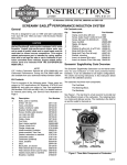
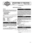
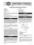
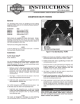
INSTRUCTIONS
-J01515
®
REV. 3-31-99
Kit Number 91531-00
ACCESSORY FAN KIT
General
Remove And Relocate Stock Horn (FLHT)
This kit fits 1992 and later FLHR and FLHT models.
1.
Refer to applicable Service Manual, Section 8. Remove
horn and its bracket. Disconnect wires from horn and
remove large nut that secures horn to horn bracket. Set
horn aside.
2.
Refer to FLT Service Manual, Section 2 and remove
outer fairing.
3.
See Figure 1. Locate connector [2], refer to FLT Service
Manual, Appendix A, Deutsch Electrical Connectors.
Follow directions given and remove socket terminal
from cavity 6 (yellow/ black wire). Cut socket terminal
from wire and cover wire end with electrical tape.
4.
See Service Parts illustration. Locate horn relocation
harness (14) from kit and insert socket terminal (on
yellow/black wire) into cavity 6 of connector [2B]. Plug
two halves of connector together.
5.
See Figure 1. Route black wire with double spade
terminal (on horn relocation harness) to cigarette lighter.
Disconnect black wire from cigarette lighter. Connect
double spade terminal to cigarette lighter and reconnect
stock black wire on the “open” double spade terminal.
6.
Connect the two remaining terminals on the horn
relocation harness to the horn terminals. The horn is not
polarity sensitive so leads may be attached to either
horn terminal.
7.
See Service Parts illustration. Locate two horn brackets
(12) and flat rubber washer (7). Slip rubber washer on
horn stud. Take two horn brackets and install large hole
end on horn stud. Secure with metric M6 nut (16).
KIT CONTENTS
See Service Parts on pages 4-6 for kit contents.
Installation
NOTE
This cooling fan is designed to provide supplemental cooling
for motorcycles subjected to long periods of idling/parade
duty. The fan is mounted on the left side of the engine in the
area where the horn is mounted. The horn must be removed
and relocated.
1.
Remove seat.
1WARNING
To avoid accidental start-up of motorcycle, and possible
personal injury, disconnect the battery cables (negative
cable first) before performing any of the following procedures. If the positive cable should contact ground
with the negative cable installed, the resulting sparks
may cause a battery explosion and could result in death
or serious injury.
2.
Disconnect battery, negative cable first.
f1317c8x
Connector [2]
(grey)
Right support
bracket
Horn bracket
mounting point
Cigarette
lighter
Figure 1. Outer Fairing Removed (FLHT Models)
1 of 5
8.
9.
See Figure 1. Mount horn to right support bracket with
10-24x1/2 screw (4) and washer (10). Thread screw
into PEM nut. If right support bracket does not have
PEM nut drill a 7/32 in. hole at the location shown in
Figure 2 and use 10-24 nut (17),washers (10) and
screw (4) to mount horn.
Position horn so horn cover opening is facing
downward.
10. Cover terminals on stock horn leads with electrical tape
and position leads so they will not be damaged. Secure
leads with a cable strap if necessary.
3.
Remove two bolts and washers securing upper engine
mounting bracket to front and rear cylinder heads.
Retain bolts and washers for attaching new upper
engine mounting bracket from kit.
4.
Note position of fuel/vacuum hoses. Remove upper
engine mounting bracket.
CONNECTING ACCESSORY FAN HARNESS
1. See Figure 3 and Service Parts illustration. Connect
ring terminal on accessory fan harness (13) to silver
stud on main circuit breaker.
2
i01490.
1-11/16 in.
(43 mm)
Connect socket connector [4B] on accessory fan
harness to pin connector [4A] P&A accessory
connector.
CAUTION
Due to the different air cleaner backplate configurations,
take care to mount the thermostat in a suitable location in
the next step. Make certain thermostat will not contact
cylinder head or prevent normal mounting of backplate.
Orient thermostat so its leads are routed away from
components that could damage them.
PEM nut or
location for 7/32
in. diameter hole
3.
Refer to applicable Service Manual Section 4 and
remove air cleaner backplate. Position the thermostat
(part of accessory fan harness) on backplate to rear of
carburetor as described in “CAUTION” above. Mark
thermostat mounting hole locations on backplate. Drill
two 5/32 in. holes in backplate and mount thermostat
with 6-32x3/8 in. screws (3) and nuts (6).
4.
Mount fan relay in a vertical position (mounting hole up)
and secure with an existing (stock) mounting screw or
secure with a cable strap from kit.
Figure 2. Horn Mounting Hole Location (FLHT)
Remove And Relocate Stock Horn (FLHR)
1.
2.
Refer to applicable Service Manual, Section 8. Remove
horn and its bracket. Disconnect wires from horn and
remove large nut that secures horn to horn bracket.
Remove horn from chrome cover. Set horn aside.
See Service Parts illustration. Locate three horn
brackets (12) and flat rubber washer (7). Slip rubber
washer on horn stud. Take three horn brackets and
install large hole end on horn stud. Secure with metric
M6 nut (16).
MOUNTING FAN ASSEMBLY
1. See Service Parts illustration. Install fan mount (2)
(upper engine mounting bracket from kit) on front and
rear cylinder heads and secure with stock bolts and
washers. Tighten bolts to 28-35 ft-lbs.(38-47.5 Nm).
2.
Install upper stabilizer link on upper engine mounting
bracket with stock bolt and washer. On carburated
models mount enrichener bracket to underside of
upper engine mounting bracket. Check that
fuel/vacuum hoses are routed properly.
3.
Secure stabilizer link and if applicable, enrichener
bracket, with stock bolt, nut and washer. Tighten bolt to
18-22 ft-lbs.(24-30 Nm).
REMOVING STOCK UPPER ENGINE MOUNTING
BRACKET
1. On carburated models refer to applicable Service
Manual, Section 4 and remove enrichener control from
upper engine mounting bracket.
4.
Insert rubber mount stud (8) through mounting hole in
fan mount (2) and secure with 1/4 in ID washer (9) and
1/4-20 nut (18). Tighten nut to 72-96 in-lbs (8-11 Nm).
5.
Repeat Step 4 for other mounting hole in fan mount (2).
2.
Remove screw securing rear of fuel tank and gently
raise fuel tank to gain access to upper engine mounting
bracket. Place suitable blocking under tank.
6.
See Service Parts illustration. Insert rubber mount stud
(8) through bottom mounting hole in fan cover assembly
and secure with 1/4 in ID washer (9) and 1/4-20 nut
(18). Tighten nut to 72-96 in-lbs (8-11 Nm).
3.
Remove bolt attaching stabilizer link to upper engine
mounting bracket. Retain bolt, nut and washer for
reattaching stabilizer link later.
7.
Position fan assembly so holes in upper mounting tabs
on fan cover assembly engage rubber mount studs in
upper engine mounting bracket.
3.
Remove left front fuel tank Torx screw. Mount horn
(without chrome cover) at left front of fuel tank with Torx
screw.
4.
Route stock horn wires forward and reconnect to horn.
Fan Installation
-J01515
2 of 5
f1431b8x
Main circuit
breaker
Silver post
P&A Accessory connector
[4A]
Figure 3. View With Seat Removed
8.
Install 1/4 in. inside diameter (ID) flat washers (9) and
1/4-20 locknuts (18) on upper studs. Tighten finger tight.
15. On carburated models mount enrichener control to
enrichener bracket.
9.
See Service Parts illustration. Install lower mounting
bracket (5), 1/4 in. ID flat washer and 1/4-20 locknut on
rubber mount stud. Tighten finger tight.
16. See Service Parts illustration. Check that a cable strap
secures fan motor leads at fan mount (2). Arrange
accessory fan harness under seat so harness and
fuseholder will not be pinched/damaged when seat is
installed. Secure harness with cable straps from kit.
10. Remove upper front bolt and washer from inner primary
housing. Insert bolt through lower mounting hole in lower
mounting bracket and tighten to 18-21 ft-lbs (24-28 Nm).
17. Carefully remove blocking from under rear of fuel tank
and install screw at rear of fuel tank .
11. Tighten the three 1/4-20 fan mounting nuts to 72-96 inlbs (8-11 Nm).
12. Route fan motor leads over upper engine mounting
bracket at location indicated with a dotted line in Service
Parts illustration. Install a cable strap to secure fan
motor leads as shown.
1WARNING
Always connect the positive battery cable first. If the
positive cable should contact ground with the negative
cable installed, the resulting sparks may cause a battery
explosion resulting in personal injury and could result in
death or serious injury.
CAUTION
14. Reconnect battery, positive cable first.
Make certain motor leads are connected as specified in
the next step. Reversed leads would reverse fan rotation
and decrease cooling efficiency which could cause
engine damage.
13. Connect motor leads to the sealed butt connectors on
the accessory fan harness (13). Connect as follows:
Blue fan motor lead to Black harness lead
Black fan motor lead to Blue/Black harness lead
14. Refer to FLT Service Manual, Appendix A, “SEALED
BUTT SPLICE CONNECTORS” for instructions on
crimping and heating connectors to melt the sealant.
J01515
15. Install seat.
1WARNING
After installing seat, pull upward on front of seat to be
sure it is locked in position. If seat is loose, it could shift
position during vehicle operation and startle the rider,
and could result in death or serious injury.
NOTE
The cooling fan is thermostatically controlled and will only
operate when the thermostat senses cooling air temperature
of approximately 140° F. Cooling air movement is from left to
right, that is, air is drawn in through slots in fan cover and
blown across cylinders and cylinder heads.
3 of 5
®
Service Parts
Part No.91531-00
3/99
Accessory Fan Kit
Fan relay &
connector
Cavity
30
85
86
87
87A
Fan harness, item (13) in
list on page 5
Black wire, connect to Blue fan
motor lead
Wire color
Black
Black
Blue
Blue/black
Not used
Cavity
1
2
3
4
Blue/black wire,
connect to Black
fan motor lead
Wire color
Blue
Plug-not used
Plug-not used
Black
[4B] connect to
[4A] P&A Acc.
connector
15 amp fuse &
fuseholder
Thermostat, mount to air
cleaner backplate with
6-32 screws and nuts.
Ring terminal,
to silver stud
main circuit
breaker
Horn terminals
Horn relocation harness for
FLHT models, item (14) in list
on page 5
Horn bracket, item (12) in list
on page 5
Yellow/black wire,
connect to cavity 6
of connector [2B]
Black wire, connect
to Black lead at
cigarette lighter.
J01515
4 of 5
®
Service Parts
Part No.91531-00
3/99
Accessory Fan Kit
Stock hardware
Hole with grommet
through which fan
motor leads are routed.
8
9
9
11
18
2
9
8
Fan cover screw
Stock hardware
Cable strap location to secure
fan motor leads
15
5
8
9
Stock hardware
(inner primary
cover)
Item
1
2
3
4
5
6
7
8
9
18
Description
Qty. *
Cable strap
3
Fan mount, (top engine mount)
Screw, 6-32x3/8 in.
2
Screw, 10-24x1/2 in.
Bracket, lower mounting
Nut, 6-32
2
Washer, rubber, 1/4x3/4x3/64
Mount, rubber
3
Washer, 1/4x5/8x1/16
6
Part No.
10065
not sold
2517
2592
not sold
60031-61
6265
not sold
6703
In addition to the above Service Parts, the following
Repair kits are available at your Harley-Davidson dealer:
Fan motor
Part no. 74452-00
Thermostat
Part no. 74453-00
J01515
Fan cover assembly is assembled
on fan motor as received in kit.
Exploded view has been used for
illustration purposes only.
Item
10
11
12
13
14
15
16
17
18
Description
Washer, #10
Bracket , enrichener control
Horn bracket, straight
Fan harness
Horn relocation harness
Fan assembly
Nut, flanged M6
Nut, 10-24
Nut, 1/4-20
Fan assembly
Qty. *
2
3
6
Part No.
6716
not sold
not sold
not sold
not sold
not sold
7495
7624
7686
Part no. 74454-00
5 of 5