1
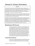
www.allstyles-scooters.com
Allstyles Scooters
www.allstyles-scooters.com
INDEX
Introduction
Layout of controls
Operating instructions
Oil to be used for the fuel mixture
Running – in
tire pressure
4
5
6
8
9
9
Operating and maintenance:
Common operations to carry out
Maintenance
Summary of Instruct. for Maintenance
Cleaning the vehicle
Operating instruction : Fault finding
General specification
Accessories
Electrical equipment
Identification data
Specific characteristics
12
24
25
27
28
31
33
34
36
38
www.allstyles-scooters.com
Fig. 1 - Vespa Super
INTRODUCTION
The PIAGGIO CO. wishes to welcome you into the family of Vespa owners and take this
opportunity of thanking you for your preference. We feel sure that this scooter will
give you complete satisfaction.
Because of its characteristics (comfort, limited consumption, easy driving, quiet engine,
clean lines, etc.) the Vespa has a wide range of uses for practical operation and
pleasure trips. Long journeys on the Vespa will not fatigue you and you will quickly
appreciate its first class performance.
This booklet, with its simple instructions on operation and maintenance will furnish you
all the information necessary for gaining a complete working knowledge of your
vehicle.
N. B. - This booklet illustrates the models of Vespa «Super», provided with 150 cc.
engine and 125 cc. engine. The operation and maintenance instructions are valid for both
models; the specific characteristics of each model are reported at page 41.
www.allstyles-scooters.com
1. Clutch control (lever) and gear change (twist grip) - 2. Front brake lever - 3.
Throttle twist grip - 4. Main switch unit - 5. Front brake shoes - 6. Rear brake pedal 7. Kickstarter - 8. Gear selector - 9. Rear brake shoes - 10. Clutch - 11. Carburettor
and air cleaner - 12. Choke control - 13. Fuel cock - 14. Fuel tank cap.
Fig. 2 - Installation of controls and transmissions
www.allstyles-scooters.com
OPERATING INSTRUCTIONS
SECURITY LOCK
The vehicle is provided with two security locks, the
one relates to the steering column ( locking and
unlocking the handlebar) and the other one for
locking the tool box. Both operated by the same
key.
STEERING LOCK
a) Locking the handlebars
anticlockwise
NOTES
To lock the vehicle, turn the handlebars
up to the limit stop; rotate the key anticlockwise and
push inwards, so that it thrust the sliding bar against
the steering column. To ease the insertion of the
sliding bar into the hole of the steering column,
slightly turn the handlebars from the limit stop
clockwise.
When the handlebars are locked the key will now
spring back to its original position and can then
be withdrawn.
Both the Iocks should not be lubricated.The key
can be extracted from the loci even if the handle
bars are free
Fig. 3 - Steering lock
1. Normal position - 2. Locked position
Note - The arrows indicate the operation to be carried out for locking (1) and for
unlocking (2).
www.allstyles-scooters.com
Fig. 4 - Application of dual saddle
N. B. - For access to fuel tank push the button indicated by arrow and pivot the seat
on its forward edge
www.allstyles-scooters.com
b) Unlocking the
Handlebars
To release the handlebars, insert the key in the
lock, turn it to the left and pull it back; then
turn the handlebars in the normal position.
FUEL SUPPLY
Use a mixture of oil and petrol i. e. 2%, Pure
Mineral Oil SAE 30 (i. e. about 1 /4 pint of oil
per 11 /, gals of petrol ). Do not use detergent
oils.
ACCESSING TO FUEL TANK
The fuel tank is provided with a hinged plug
located under the saddle.For access to fuel tank
when the dual saddle is mounted, pivot the
saddle on its forward edge, after having
released the rear attachment as shown at fig.
4.
NOTES
Ensure that the fuel tank breather is always clean.
Fig. 5 - Engine section
1. Group carburettor air cleaner - 2. Piston - 3. Crankshaft - 4. Clutch - 5. Mainshaft and
gear pinion assy. - 6. Gear shifter - 7. Flywheel magneto - 8. Kickstarter - 9. Crankcase
swinging arm clutch side (pivoted to the frame).
www.allstyles-scooters.com
OPERATING INSTRUCTIONS
BEFORE OPERATING THE
VEHICLE
Unscrew the plug on the gear box marked OLIO
(second detail, bottom, L. H., fig. 18) and check that
the oil is on a level with the hole when the vehicle is
standing upright.
RUNNING - IN PERIOD
For running -in the first 2000 Km. ( 1200 mls ), do
not maintain the throttle fully open for long
periods. After first 1000 Km. (600 mls) change oil in
gear box (see
fig. 18) and check that all
bolts are tight. Check that the carburettor is well tight
on the crankcase to avoid any possibility of air
filtrations.
nuts and
TIRE PRESSURE
Front
1.1 Kg/cm2 (15.5 p.s.i.)
Rear
1.3 Kg/cm2 (18.5 p.s.i.) with one up
2.3=2.5 Kg/cm2 (32.7=35.5 p.s.i.) with two
up.
Fig. 6 - Operations for starting
A: Open the fuel tap - B: Selector in neutral - C: Pull out the choke control (with cold
engine) - D: Bring throttle twist grip to idling position - E: Operate kickstarter.
www.allstyles-scooters.com
OPERATING INSTRUCTIONS
STARTING
Carry out the operations indicated on fig. 6. Do not
use the choke when the engine is warm; as soon as
the engine is running smoothly bring the choke
control back to its normal position.
SETTING THE SCOOTER
IN MOTION
first
With the engine running at idling speed declutch and
rotate the gear change twist grip to the position of
gear (fig. 7). For setting the vehicle in motion slowly
let in the clutch and gradually open the throttle.
GEAR CHANGE
Close the throttle. declutch and rotate the gear
change grip to a higher or lower gear, as the case
may be (fig. 7).
STOPPING THE ENGINE
Before stopping the engine change to neutral
and then switch off the ignition.
NOTES
In case of hard starting see page 16. Do not attempt
to ride the vehicle unless the key is inserted and the
handlebars rotate freely. When it is necessary to
decelerate do not hesitate in changing down.
www.allstyles-scooters.com
Fig. 7
1. Gear change twist grip - 2. Clutch control lever - 3. Gear change cables - 4. Gear
shifter - 5. Selector stem - 6. Selector spider - 7. 1st gear - 8. 2nd gear - 9. 3rd gear - 10.
Top gear - 11. Mainshaft - 12. Spring gear - 13. Clutch.
N. B. - The positions 1 - 2 - 3 - 4 on the change twist grip correspond to bottom, 2nd, 3rd
and top gear respectively; the n 0 u indicates neutral.
www.allstyles-scooters.com
OPERATING AND MAINTENANCE: COMMON OPERATIONS TO CARRY OUT
Fig. 8 - Removing engine cowl.
1. Lever for locking cowl. - 2. Front locating pin - 3. Clasp securing cowl to chassis - 4.
Rear hooked pivot pin.
REMOVAL OF ENGINE COWLING
- Pull the lever (1) and turn to release from cowling. Swing the cowling outwards so that
the front locating pin (2) is free of its housing.
- Lift the cowling upwards from the front pivoting on its rear section : so as release the
clasp (3) from the chassis bracket.
- Pull the cowling outwards on the locating pin (4) so as the latter clears its housing, thus
releasing the cowling.
- For reassembly carry out the reverse procedure.
www.allstyles-scooters.com
Fig- 9 - Fuel supply and distribution diag,
1. Fuel tap - A) Reserve; B) Open; C) Closed - 2. Float - 3. Carburettor and air cleaner 3/1. Air filter - 4. Starter jet - 5. Throttle slide set screw - 6. Throttle slide - 7. Main jet air
calibrator - 8. Air calibrator on mixer - 9. Mixer - 10. Main jet - 11. Slow running jet - 12.
Slow running jet air calibrator - 13. Oil filler plug - 14. Slow running adjuster screw - 15.
Starter valve - 16. Inlet port - 17. Transfer ports - 18. Exhaust port.
www.allstyles-scooters.com
OPERATING AND MAINTENANCE: COMMON OPERATIONS TO CARRY OUT
ADJUSTMENTS ON CARBURATOR
For adjusting the idling turn the slow running adjuster screw (fig. 9 n. 5).
- On the carburettor body a set screw is provided for adjusting the throttle cable play; this
screw is to be reset only if necessary or on dismantling and reassembly operations.
- On the air cleaner case, opposite to said screw, is a plugged hole. When this plug is
removed the spring loaded idler adjusting screw is accessible (Fig. 9, n. 14).
To avoid carburation troubles we recommend that this adjustment is carried out by a
Vespa dealer.
STARTING UP when the engine is flooded
In the case of difficulties caused by flooding (presence of unvaporised mixture in the
cylinder), the following methods can be used:
- Attempt push starting : engage the 2nd gear, declutch, push the vehicle to a certain
speed, sharply release the clutch and when the engine starts declutch.
- Close the fuel tap, remove the sparking plug (fig. 10) and clean; then kick over the
engine several times.
Screw in the sparking plug securely, open the fuel tap and start the engine.
Fig. 10. Dismantling spark plug
www.allstyles-scooters.com
OPERATING AND MAINTENANCE: COMMON OPERATIONS TO CARRY OUT
SPARKPLUG REMOVAL
Remove engine cowl (Fig. 8), disconnect the H. T.
lead and extract the spark - plug using the box
wrench as indicated in fig. 10.
CHANGING OIL IN GEAR CASE
Drain off through hole Fig. 18, 2nd detail, letter (S).
Introduce a small quantity of flushing oil, run the
engine a few minutes to ensure thorough circulation
and cleaning and drain off again.
Refill gear case with about 250 qrs. of new oil (up to
level of filling hole).
DISMANTLING AIR FILTER
For extracting the air filter (A) (fig. 11 ) from the
air filter case remove the engine cowl (fig. 8) and air
cleaner case cap. Unscrew the two screws (B)
securing the air filter and extract the latter
component.
NOTES
On reassembling the spark-plug ensure that it is into
the threaded hole at the correct inclination. This
operation of changing oil should be carried out with
warm engine. The air cleaner case cap can be
extracted by dismantling the two sec firing screws.
www.allstyles-scooters.com
Fig. 11 -Dismantling the air cleaner
Note - For approaching the carburettor, remove the air cleaner case.
www.allstyles-scooters.com
Fig. 12 - Dismantling cooling hood from engine (A) and head (B).
www.allstyles-scooters.com
OPERATING AND MAINTENANCE: COMMON OPERATIONS TO CARRY OUT
DISMANTLING CYLINDER HEAD Strips off engine cowling, (Fig. 8), disconnet the H.
T. lead, dismantle the Cooling hood (fastenings (B)
(C), fig. 11 ) and unscrew the 4 securing bolts by
means of a box wrench.
CHANGING WHEELS AND TIRES For dismantling the wheels from the vehicle remove
the bolts as indicated in fig. 13. On reassembly
tighten said nuts alternately and progressively.
When
a tire has to be removed, first deflate and then
remove the nuts joining the two wheel rims (Fig. 17).
BRAKE ADJUSTMENT
INSTRUCTIONS
Rotate the adjusting screws indicated in fig. 14, so
that the wheel is completely free to rotate when the
lever and brake pedal are in the resting position.
NOTES
The front and rear wheel are interchangeable one
with another providing that the tire pressures are
regulated accordingly (page 9). The braking action
should commence immediately the respective
controls are operated.
www.allstyles-scooters.com
Fig. 13 - Removing wheel from vehicle
www.allstyles-scooters.com
Fig. 14 - Brake adjustment
www.allstyles-scooters.com
OPERATING AND MAINTENANCE: COMMON OPERATIONS TO CARRY OUT
CHECKING AND SETTING THE
FLYWHEEL MAGNETIC
TIMING
1) Selector in neutral, take off the rubber
plug located on the rotor and rotate it by hand until
the contact breaker unit (fig. 15) is seen through the
hole of the flywheel rotor.
2) At the position indicate in the figure the contact
breaker points (A) should start to open, i. e. when
the extremity of the coil is at a distance of 2-4 mm.
(0.078" - 0.15) from the respective pole shoe.
3) By rotating again the rotor by hand, the max.
opening should be between the limits 0.3 to 0.5 mm.
(0.011" to 0.019").
4) If the conditions as per points 2) and 3) are not
obtained, rotate the screw (B) and rotate the cam
(C) until foresaid conditions are obtained.
NOTES:
In order not to disturb ignition timing, do not slacken the stator plate or coil securing
screws. If necessary to adjust the spark advance, consult the Service Station. Ensure
screw (B) is tightened after having finished the operation.
Fig. 15 - Operations for checking the <magnetic> timing of the flywheel
www.allstyles-scooters.com
OPERATING AND MAINTENANCE: COMMON OPERATIONS TO CARRY OUT
SUBSTITUTING BULBS
Should one of the headlamp bulbs fail, be fore fitting
a replacement, check the real light bulb for
serviceability and vide versa
SETTING THE HEADLAMP
The correct setting of the main beam car be obtained
both horizontally and vertically as follows:
Check that both front and rear tires are inflated to
correct pressures; i. e. 1.1 and 2.5 Kg/cm² ( 15.5 and
35.5 p.s.i.). Place the scooter on a level floor in front
of a white wall as seen in Fig. 16. Start the engine
hold the throttle control twist grip at about 1 /3 and
set the switch on <main beam> With two persons on
the Vespa, slacken the device securing the
headlamp, then move the latter as required, in order
that the beam axis coincides with point < 0 > or the
wall. Tighten the screw firmly.
NOTES
Before switching on the new light bulbs check (on assy.), that the socket contact points
are efficient. Do not wipe down with a cloth or contact with finger the reflector. This
operation can be carried out also with the driver only sitting on the saddle. In this case, of
course, the beam alignment should be altered whenever the scooter is beefing ridden by
both driver and passenger.
Fig. 16 - Setting the headlamp
N. B. - The point < 0 > is valid for setting with one or two persons mounted
Note: m. 5 = 16 FT approx.; m. 0.92 - 0.94 = 3 FT approx.
www.allstyles-scooters.com
Fig. 17 - tire removal
www.allstyles-scooters.com
MAINTENANCE
When difficulties of starting or running occur, check the spark plug:
- Clean the spark plug electrodes with a steel wire or emery cloth and adjust the gap 0,6
mm. (0".023). Check porcelain insulation: if cracked or broken change the plug. Clean in
neat petrol.
It is advisable not to change the type of spark plug prescribed by factory.
Every 4000 Km (2400 mls):
1)
Check oil level in gear case.
2) De-coke the engine (cylinder head, piston crown and cylinder ports). Ensure that
not residual carbon deposits remain inside the cylinder. Clean the exhaust pipe using a
hooked steel wire.
3)
Grease front hub through the appropriate nipples and lubricate the speedometer
drive and transmission, the brake lever and gear selector.
4)
Remove the air filter, (see page 15), clean by agitating in an oil petrol bath and if
possible air blast dry.
Every 8000 Km (4800 mls):
1)
Change oil in gear case (see pag. 15).
2)
Grease control cables and lubricate the felt lubricating pad on flywheel.
3)
Clean, and if necessary, register the contact breaker points (fig. 15). To avoid a
faulty ignition or some other defects, consult your Service-Station for this operation.
www.allstyles-scooters.com
SUMMARY OF INSTRUCTIONS FOR MAINTENANCE AND LUBRICATION
PRINCIPAL OPERATIONS TO CARRY OUT:
Engine: At each refilling (lubricated by oil in fuel)
Front and rear dampers (only if defective * )
4000 Km. (2400 mls)
Gear box (top up)
Fulcrum points of brake lever and pedal
Speedo drive and transmission Gear selector
Front suspension
Cleaning air filter (in petrol)
Decoking silencer
Decoking cylinder head and piston *
Cleaning and adjusting sparking plug electrodes
Every 8000 Km. (4800 mls)
Gear box (Change oil)
Greasing control cables
Felt lubricated pad on flywheel
Cleaning and adjusting contact breaker points (check timing *)
Lubricants
Oil SAE 30.
Esso Multi – Purpose Grease H
Mobilgrease MP
Shell Retinax A
2% by volume Pure minera oil SAE 30.
Esso Univis J 43.
Notes
* Consuls your Service Station.
www.allstyles-scooters.com
Fig. 18 - Lubricator scheme
Notice: 2nd detail, L. H.; < S > indicates the oil draining hole from engine.
LAYING UP
We recommend that the following operations be carried out:
1) - Clean down the vehicle.
2) - With the engine stationary and throttle fully opened, introduce 40 cc. of OIL SAE 30
through the appropriate hole on the air cleaner case (n. 13, fig. 9). After said operation
depress the kickstarter three or four times.
3) - Drain off all fuel contained in the fuel tank; then grease over all unpainted metallic
parts; next raise the wheel off the ground by placing wooden chocks under the footrest.
www.allstyles-scooters.com
CLEANING THE VEHICLE
Notice:
Washing and polishing operations should not be carried out in the sun, particularly
during the summer when the bodywork is warm.
Under no circumstances should petrol or Diesel oil be used for washing painted
surfaces or plastic material as they will deteriorate.
Always wash the scooter before polishing.
1) Engine.
For cleaning the exposed surface of the engine use paraffin, a brush and clean rags.
2) Bodywork. - Washing.
Painted parts should be washed down using a low pressure hose. Do not use a high
pressure system as grit may be forced into the paint.
When the dirt and grime becomes soft, sponge off using one of the << car type >>
shampoos available (use a product of the type Rolene and Teepol, which are employed
in aqueous solution, 3 = 5% by weight). First, lightly wash the painted surface of the
scooter, in order to avoid scratching. Thoroughly rinse with plenty of water. Dry off using
a clean chamois leather to eliminate water marks.
- Spots.
To remove spots caused by tar, grease, insects, etc., rub gently with a soft cloth dipped
in oil or turpentine. More persistent marks can be removed with a solution of warm water
and car shampoo. Carry out this procedure periodically, to eliminate permanent
paintwork damage.
- Polishing.
If after washing, as previously described, the original condition is not restored, apply
evenly a thin coat of good quality wax polish and shine with a soft cloth, rubbing gently in
a side to side manner.
www.allstyles-scooters.com
FAULT FINDING
When the machine does not run properly, inspect and rectify as explained below.
If the suggested remedies are not sufficient in eliminating the trouble, consult your
Dealer.
Fault finding
HARD STARTING
1. - Fuel system – Carburation
- Ignition.
Remedies
Lack of fuel.
Turn to Reserve and refit as soon as possible.
Filter, jets, fuel tap, carburettor
body clogged or dirty.
Remove, wash in petrol and blow dry.
Engine flooding.
See page 14.
Air cleaner choked or dirty.
See page 15.
Sparking plug dirty - Porcelain
of sparking plug cracked.
Disconnect the plug lead. Check if sparking occurs
between lead and crankcase when the kickstarter is
operated.
Breaker points dirty, worn or pitted;
men between point incorrect
Consult your Dealer.
www.allstyles-scooters.com
Fig. 19 Ignition circuit
1. Flywheel coil - 2. H. T. coil - 3. Flywheel cam - 4. Contact breaker - 5. Condenser - 6.
Sparking plug - 7. Engine cut-out.
www.allstyles-scooters.com
VARIOUS RUNNING DEFECTS
1 – Lack of power – High
fuel consumption
Spark plug misfiring (see fig. 19 ).
check
Clean or substitute. Clean the contact breaker Check the electrode gap of the sparking plug;
the flywheel timing (see page 21).
Silencer (or engine) choked.
Clean (see page 24).
Sparking plug loose in the cyl.
head.
Screw down with a wrench.
Cylinder head loose.
Set head accurately and tighten nuts.
Air filter choked or dirty or choke
controlincorrectly set.
Wash in neat petrol, air blast dry. Check choke
control mechanism.
2 - Defective electrical equipment.
Wire terminals disconnected or
carelessly connected.
Carefully check and connect.
Headlight beam incorrectly set.
Adjust (see page 22)
Defective bulbs.
Remedies
See page 22 for substituting.
Notice:
When the carburettor is defective, the engine is lack in compression, noisy engine,
defective suspension and brakes, general mechanical failures, consult your Dealer.
When overhauling of the front suspension, grease the wheel bearings with FIAT JOTA 3
or SHELL ALVANIA 3 (or SHELL RETINAX A).
www.allstyles-scooters.com
GENERAL SPECIFICATION
Engine (see fig. 5) : Single horizontal cylinder two stroke rotary distribution: i. e.,
carburated mixture is regulated by the crankshaft rotation. Performance and
specifications concerning Vespa 150 cc. and 125 cc. at pages 42 - 43. The engine is
pivoted to the vehicle's chassis through the crankcase swinging arm, clutch side (fig.
20). The rear wheel is fitted on the outer side of the drive shaft.
Lubrication of engine components (piston, cylinder, crankshaft, main bearing) is
effected by the oil in the fuel mixture. The clutch and gear box function in oil bath.
Fuel supply (see fig. 9): gravity feed with mixture of oil and petrol. 3 way tap :
<closed>, <open>, <reserve>. Carburettor located in the air filter housing, provided
with a throttle slide.
Ignition by means of a H. T. flywheel magneto external coil.
Clutch (see fig. 5) : multiplate on the layshaft. The unit is operated by a lever
located on L. H. handlebars and adjustable cable.
Gear box (see fig. 7): four speed drive with mesh gears. Operated by the twist grip on L.
H. handlebar which functions in conjunction with the clutch control lever.
Transmission ratio engine to driving wheels see at pages 38-39.
Starting (see fig. 6) : by means of a kickstarter on the R. H. side of the vehicle.
Cooling: by means of a centrifugal fan. Air intake: located inside the frame.
Muffler: expansion and absorption type.
Integral chassis (fig. 1) : pressed sheet steel, streamlined monocoque type structure.
Handlebars: Light alloy casting comprising speedometer. All transmission cables and
various controls are concealed therein.
Steering column, suspension : On the lower end of the steering column is pivoted
the front wheel swinging hub. Front and rear suspensions with helical spring and
double acting hydraulic damper.
Wheels: Interchangeable and made up of pressed steel flanges; 3,50 - 8" tires.
Saddle: single saddle or dual saddle (optionally instead of single and luggage rack).
Brakes: cable operated expanding type. Front brake is operated by hand - lever (R. H.
handlebars) ; the rear brake is pedal operated on R. H. footboard.
Parking stand: a two legged stand with a central return spring.
Steering lock: with a sliding bar acting on the steering column.
www.allstyles-scooters.com
Fig. 20 - Installation of engine and suspension
1. Steering column and front suspension - 2. Engine 3. Crankcase clutch side with
swinging arm pivoted to frame 4. Rear suspension spring and hydraulic damper assy.
STANDARD TOOL KIT
1 four ended box wrench (1 1 - 14 - 21 - 22 mm.) ; two double open - ended wrenches (1
1 - 14 and 7 - 10 mm.) ; one single open ended wrench (8 mm.). One screwdriver. These
tools are contained in a canvas roll together with this booklet which is placed in the tool
box, left side of vehicle.
www.allstyles-scooters.com
ACCESSORIES
On request the vehicle can be furnished with the following accessories:
Dual saddle of a special long shape suitable for two persons (driver and passenger),
provided with a hand grips for passenger.
Rear passenger saddle can be secured on the frame instead of the luggage rack, the
central spring can be adjusted to the passengers weight. In place of it can be supplied :
a foam rubber pillion seat to be applied over the luggage rack, the latter being issued as
standard equipment.
Spare wheel and bracket which can be secured to the frame.
Windscreen: extremely easy to be secured on the handlebars.
Fig. 21 - Application of accessories: passenger saddle (after having removed the luggage rack),
pillion seat, spare wheel
www.allstyles-scooters.com
ELECTRICAL EQUIPMENT
Fig. 22- Installation of electrical equipment
1. Black - 2. White - 3. Green - 4. Brown - 5. Red - 6. Blue - 7. Yellow - 8. Violet.
NOTE:
A full color and more detailed wiring diagram can be downloaded at
www.scooterstation.com
www.allstyles-scooters.com
ELECTRICAL EQUIPMENT
The electrical equipment is fed by alternating current, nominal voltage 6 V. This
equipment consists of the following lighting and signalling devices: The headlamp,
dia. 115 mm., 6 V - 25/25 W bulb ( main and dipped beam) ; front pilot light and
light for registration plate 6V - 5 W ; Speedometer light 6 V - 0,6 W, Stop light 6
V - 10 W ; Horne 6 V a. c.. The flywheel is provided with 6 poles.
Fig. 23 - Installation of electrical equipment - see Fig. at previous page and electrical
connections - see Fig. at the present page.
Fig. 24 - Light and dip switch
0-1-2: Switching lever positions. - 0. Lights off. - 1. Pilot light and tail lamp on. - 2. Head
light and tail lamp on - A: Main and dipped beam switch - B: Horn button - M: Engine cutout.
www.allstyles-scooters.com
IDENTIFICATION DATA
They consist of a prefix VBC1 for Vespa <Super 150> and VNC1 for Vespa <Super
125> and progressive number.
The chassis prefix and serial number, stamped on the frame and engine, identify the
vehicle as prescribed by law, are always carried out on the documents pertaining to the
vehicle: these numbers should be quoted when ordering spare parts.
Fig. 25 - Serial number stamped on engine.
www.allstyles-scooters.com
Fig. 26 - Serial number stamped on frame.
www.allstyles-scooters.com
SPECIFIC CARACTERISTICS OF THE VESPA SUPER
Vespa <Super 150> : PERFORMANCE AND SPECIFICATIONS
Consumption (accord to CUNA Standard):
2.2 It/100 Km. ( 107.5 mls/U.S. gal.; 129.2
mls/imp. gal.), gasoline-oil mixture i. e. 2%
oil.
Max speed (CUNA Standards)
90 Km/h (55.92 mph.).
Carrying capacity
2 persons and 10 Kg. (22 lbs) of luggage.
Range
350 Km (217.5 mls)
Max. fuel capacity:
incl.
-of
7.7 It. (2.0 U.S. Galls or 1.7 imp. galls (
1.4 It. - 0.37 U. S.galls or 0.31 imp. galls
reserve).
Wheel base
Handlebar width
Total length
Max. height
Min. ground clearance
Turning radius
Total dry weight
1200 mm (47".24)
670 mm (26".38)
1740 mm (68".50)
1015 mm (39".96)
130 mm ( 5".12)
1500 mm (59".05)
87 Kg. ( 191.8 Ibs )
ENGINE:
two stroke rotary distribution : i. e.,
carburated mixture is regulated by the
crankshaft rotation.
Displacement
Bore
Stroke
Compression ratio
145.45 cc. - 8,87 cu. in.
57 mm - 2".24.
57 mm - 2".24.
1 :7.4.
H. T. flywheel magneto external coil ignition
Spark advance:
22° ± 1 ° before T. D. C.
Sparking plug:
Transmission ratio engine to driving wheels
Bottom gear
2nd gear
3rd gear
4th gear
Bosch W 225 T 1
Champion L 86; AC 43 F
Marelli CW 230 A-T or CW 225 N-T
KLG F 70 or F 75.
1 : 13.35
1 : 9.32
1 : 6.64
1 : 4.73
www.allstyles-scooters.com
Vespa <Super 125> : PERFORMANCE AND SPECIFICATIONS
Consumption (accord to CUNA Standard)
2.1 It/100 Km. (112.6 mls/U.S. gal.; 135.3
mls/imp. gal.), gasoline-oil mix ture i. e.
2% oil.
Max. speed (CUNA Standards)
85 Km/h (52.8 mph.).
Carrying capacity
2 persons and 10 Kg. (22 Ibs) of luggage.
Range
370 Km (229,9 mls) Max. fuel capacity: 7,7
It. (2.0 U.S. galls or 1.7 imp. galls (incl. 1.4
It. - 0.37 U. S, galls or 0.31 imp. galls - of
reserve).
1200 mm (47".24)
670 mm (26".38)
1740 mm (68".50)
1015 mm (39".96)
130 mm (5".12)
1500 mm (59".05)
87 Kg. (191.8 Ibs)
Wheelbase
Handlebar width
Total length
Max. Height
Min. ground clearance
Turning radius
Total dry weight
ENGINE:
two stroke rotary distribution: i. e.,
carburated mixture is regulated by the
crankshaft rotation.
Displacement
Bore
Stroke
Compression ratio
123.4 cc. - 7.53 cu. in.
52.5 mm - 2".07.
57 mm - 2".24.
1 :7.7.
H. T. flywheel magneto external coil ignition.
Spark advance
21 ° ± 1 ° before T. D. C.
Sparking plug
Transmission ratio engine to driving wheels
Bottom gear
2nd gear
3rd gear
4th gear
Bosch W 225 T 1
Champion L 86
AC 43 F
Marelli CW 230 A-T or CW 225 N-T
KLG F 70 or 75.
1 : 13.35
1 : 9.32
1 : 6.64
1 : 4.73
www.allstyles-scooters.com