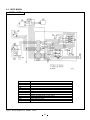
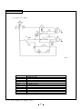
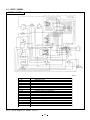
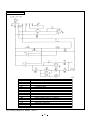
1
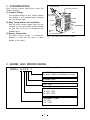
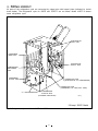
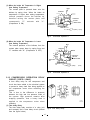
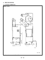
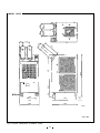
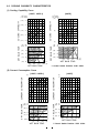
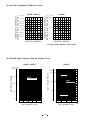
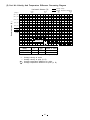
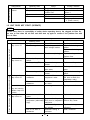
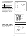
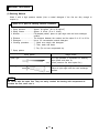
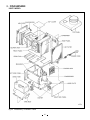
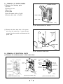
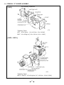
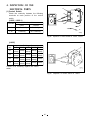
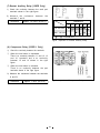
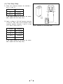
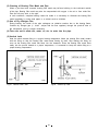
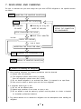
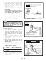
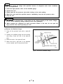
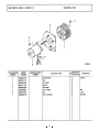
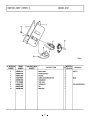
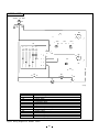
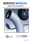
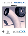
10SFE · 15SFE · 15SFE-1
FOREWORD
This manual has been published to service the MovinCool 10SFE, 15SFE and 15SFE-1.
The
purpose of this manual is making up for the previous manual (GMZR-03A and GMZR-06) in
modifying specification.
Please use this service manual in servicing (maintenance, inspection,
repair, etc.) the unit.
TABLE OF CONTENTS
CONSTRUCTION & OPERATION
1.
2.
3.
4.
5.
6.
Page
CONSTRUCTION ..........................................................................................................2
MODEL AND SPECIFICATIONS.................................................................................2
PIPING LAYOUT ...........................................................................................................6
CONTROL BOX ............................................................................................................7
SYSTEM COMPONENTS AND FUNCTIONS ............................................................8
SPECIFICATIONS........................................................................................................15
REPAIR
1.
2.
3.
4.
5.
6.
7.
8.
9.
Page
TROUBLESHOOTING .................................................................................................24
PREINSPECTION ........................................................................................................27
DISASSEMBLE............................................................................................................31
INSPECTION OF THE ELECTRICAL PARTS .........................................................36
INSPECTION OF THE REFRIGERATION CYCLE..................................................42
REPAIR OF REFRIGERATION CYCLE....................................................................42
EVACUATING AND CHARGING ...............................................................................45
PARTS CATALOG.......................................................................................................49
WIRING DIAGRAM .....................................................................................................80
CONSTRUCTION
AND
OPERATION
1
1. CONSTRUCTION
COOLING AIR
Spot cooling system (MovinCool) have the
following features;
HOT AIR OUTLET
(1) Compact Design
COLLING
AIR DUCT
The innovative design of spot cooling systems
has resulted in one compact design, replacing
the two separate units.
FILTER
FILTER
(2) Easy Transportation and Installation
INTAKE
AIR
(TO CONDENSER)
With the whole cooling system built into one
compact unit, the spot cooling system requires
no pipe work and can be transported and
installed easily.
INTAKE
AIR
(TO EVAPORATOR)
(3) Energy Conservation
The spot cooling system is economical.
Because it cools only the area or object
needed to be cooled.
Fig.1
zq311g
Air Flow of Spot Cooling System
2. MODEL AND SPECIFICATIONS
MODEL - 15 S F E - 1
- 1: With Temperature Control
No mark: Without Temperature Control
European Spec.
Floor Type
Shows Thermal Allowable Load
S: 40℃, 50%
H: 45℃, 50%
Compressor Output
10: 1HP
15: 1.5HP
2
The refrigeration cycle of 15SFE and 15SFE-1 are as shown below. Model 10SFE is almost
same refrigeration cycle.
[REFRIGERANT CYCLE]
CONDENSER
EVAPORATOR
CAPILLARY TUBE
COMPRESSOR
DESUPERHEATER
ACCUMULATOR
FLOW OF
REFRIGERANT
CONDENSER
FAN MOTOR
ACCUMULATOR
(※)DESUPER
HEATER
CAPILLARY
TUBE
EVAPORATOR
COMPRESSOR
zq312g
※Except 10SFE Model
Fig.2
Refrigeration Cycle of Model 15SFE & 15SFE-1
3
2-1 COMPRESSOR
The compressor used is a hermetic rotary type. The compressor and the compressor motor are
in one casing.
(1) Construction
The construction of the rotary type compressor is divided into two mechanisms that are the drive
mechanism and compression mechanism. When the rotor shaft of the motor turns, the roller of
the compressor rotates to absorb and compress the refrigerant.
The main parts are the rotor (drive mechanism), cylinder, roller and the lubricator.
TO CONDENSER
FROM EVAPORATOR
TERMINAL
ACCUMULATOR
STATOR
DESUPER HEATER
ROTOR
TO DESUPER HEATER
CYLINDER
VANE
ROLLER
DISCHARGE VALVE
OIL
LUBRICATOR
zq313g
Fig.3 Construction of Hermetic Rotary Compressor
(2) Compressor Motor
The compressor motor is a single phase motor and is built in the compressor.
4
2-2 CONDENSER
The condenser of model 15SFE & 15SFE-1 are a
heat exchanger using spain fins and tubes. The
condenser of Model 10SFE is a heat exchanger
using plate fins and tubes. The condenser is
used for the purpose of cooling and robbing the
heat from the refrigerant gas, which has been
compressed by the compressor into high
temperature, high pressure gas, so as to change
this gas into liquid refrigerant.
<SPAIN FIN>
2-3 EVAPORATOR
The evaporator of Model 15SFE & 15SEF-1 are a
heat exchanger using spain fins and tubes. The
evaporator of Model 10SFE is a heat exchanger
using plate fins and tubes. It is mounted at the front
face of the unit, located on the suction side of the
blower.
The purpose of the evaporator is just opposite to
that of the condenser. The state of the refrigerant
immediately before the capillary tube is completely
liquid. As soon as the liquid pressure drops, it starts
to boil, and in doing so, absorbed heat from the air
passing over the cooling fins of the evaporator,
cooling air.
2-4 CAPILLARY TUBE
<PLATE FIN>
Fig.4
Spain Fin & Plate Fin
HIGH TEMP./HIGH PRESS. LIQUID REFRIGERANT
The capillary tube causes the high pressure, high
temperature liquid refrigerant sent from the
condenser to evaporator as the refrigerant is
sprayed out through the fixed orifice in the
capillary tube. As a result, the temperature and
state of the refrigerant become low and mist-like,
and therefore it evaporates easily.
Model
Qty
10SFE
1
1.4±0.02
390
2
1.6±0.02
1300
15SFE
15SFE-1
LOW TEMP./LOW
PRESS GAS AND LIQUID MIXTURE.
Inner Dia.(mm) Length(mm)
zq315g
Fig.5
2-5 ACCUMULATOR
The accumulator is mounted on the suction pipe
between the evaporator and the compressor.
The accumulator separates the liquid refrigerant
from the gas refrigerant.
This allows only gas refrigerant to enter the
compressor.
In the accumulator, the refrigerant gas flows to
the inside of the cylindrical body and flow speed
of the gas decreases inside it.
This separates the liquid refrigerant within the gas
refrigerant due to the difference in specific weight,
causing the liquid refrigerant to accumulate at the
bottom of the accumulator.
This protects the
compressor from possible damage caused by the
compression of the liquid refrigerant.
Capillary Tube
FROM EVAPORATOR
GAS REFRIGERANT
LIQUID
REFRIGERANT
TO COMPRESSOR
zq316g
Fig.6
5
Accumulator
3. PIPING LAYOUT
All parts of the refrigeration cycle are connected by copper pipe with brazed joints (indicated by circled
areas below). The refrigeration cycle for 15SFE and 15SFE-1 are as follows. Model 10SFE is almost
same refrigeration cycle.
EVAPORATOR
INLET PIPE
CONDENSER
INRET PIPE
EVAPORATOR
OUTLET PIPE
COMPRESSOR
DISCHARGE
PIPE
CONDENSER
OUTLET PIPE
CONNECTING PIPE
(EVAPORATOR TO COMPRESSOR)
CONNECTING PIPE
(CONDENSER TO CAPILLARY TUBE)
(※)DESUPERHEATER
COMPRESSOR
SUCTION PIPE
(COVERED INSULATION)
zq317g
※Except 10SFE Model
Fig.7
Refrigeration Cycle of Model 15SFE & 15SFE-1
6
4. CONTROL BOX
The interior of the control box is shown in the figure below.
TERMINAL
BLOCK
AUXILIARY
RELAY
CAPACITOR FOR
COMPRESSOR
CAPACITOR FOR
FAN MOTOR
zs036g
[CONTROL BOX FOR MODEL 10SFE]
[CONTROL BOX FOR MODEL 15SFE]
RESTART AUXILIARY RELAY
COMPRESSOR MOTOR RELAY
TIME DELAY RELAY FOR
COMPRESSOR
AUXILIARY RELAY
TERMINAL BLOCK
CAPACITOR FOR COMPRESSOR
CAPACITOR FOR FAN MOTOR
zs037g
[CONTROL BOX FOR MODEL 15SFE-1]
Fig.8
7
5. SYSTEM COMPONENTS AND FUNCTIONS
The application of each components for 10SFE, 15SFE, 15SFE-1 are as follows.
APPLICATION
10SFE
COMPONENTS
15SFE
15SFE-1
(1) CAPACITOR (FOR COMPRESSOR AND FAN MOTOR)
(2) AUXILIARY RELAY
(3) COMPRESSOR RELAY
(4) OVERLOAD RELAY (PROTECTOR FOR COMPRESSOR)
(5) THERMOSTAT (ANTI-FREEZING)
(6) FAN MOTOR
(7) CONTROL SWITCH
(8) DRAIN WARNING SWITCH
(9) TEMPERATURE CONTROL (ROOM THERMOSTAT)
(10) RESTART AUXILIARY RELAY
(11) TIME DELAY RELAY
5-1 CAPACITOR
The capacitor is used to improve the rotary
power of the fan motor and the compressor at
first.
The specifications of each capacitor are
shown below.
Capacitor
Model
10SFE
15SFE
15SFE-1
Application
Rated Voltage Capacitance
(volt)
(μf)
For fan motor
440
5
For compressor
400
15
For fan motor
400
10
For compressor
400
25
5-2 AUXILIARY RELAY
When the current flows through the relay coil,
this creates excitation in the coil and causes it
to attract three or four contacts, resulting in
continuity between terminals 11 and 12, 13 and
14, 15 and 16, 19 and 20. These contacts
remain attracted in all operation modes (I/FAN or
II/COOL modes).
In the following case, the flow of current to the
relay coil is cut off.
(1) Drain warning switch turns on.
(2) The drain tank is full of the condensate water.
Fig.9
8
Auxiliary Relay for 10SFE, 15SFE
Fig.10
Auxiliary Relay for 15SFE-1
Fig.11
Compressor Relay for Model 15SFE-1
Fig.12
Overload Relay
5-3 COMPRESSOR RELAY [15SFE-1 ONLY]
This compressor relay turns on only when the
unit is operating in II/COOL mode, and supplies
power to the compressor. In the following case,
the relay turns off and cut the power to the
compressor.
(1) When the evaporator is frozen (when turning off
by Anti-freezing thermostat.)
(2) When the auxiliary relay turns off by the drain
warning switch
(3) When intake air temperature is dropped, after
that room thermostat turns on.
5-4 OVERLOAD RELAY (PROTECTOR)
An overload relay is used for protecting the
compressor. This protector cuts off the flow of
current to the compressor motor when an
overcurrent flows or became abnormally high
temperature in the compressor.
This overload relay is attached on the
compressor.
9
5-5 THERMOSTAT (ANTI-FREEZING)
The heat sensing tube of ther mostat is
mounted at the outlet tube of the evaporator,
and detects the evaporator temperature.
When the evaporator temperature reaches
freezing, the thermostat switch opens, and then
the current for the compressor is interrupted.
(The compressor stops working)
Fig.13
Thermostat
Fig.14
Fan Motor for 10SFE
Fig.15
Fan Motor for 15SFE & 15SFE-1
5-6 FAN MOTOR
The fan motor is single phase induction motor.
When the control switch is set to the !/ FAN,
@/ COOL position, the fan motor is activated.
The overload relay is built in the fan motor.
When the coil became abnor mally high
temperature, the overload relay operate. So, the
fan motor stops operation.
10
5-7 CONTROL SWITCH
The control switch is used to start or to stop
the operation. There are two switch positions
such as 0/OFF and ! / COOL for models
15SFE and 15SFE-1.
There are five switch positions such as 0/OFF,
!/LOW FAN, @/HI. FAN, #/LOW COOL and
$/HI. COOL for model 10SFE.
1a
1
1b
1
1a
1b
zs038g
Fig.16
Control Switch for 15SFE & 15SFE-1
SW
Position
@/HI. FAN
!/LOW FAN
0/OFF
#/LOW COOL
$/HI. COOL
Terminal
No.
1
2
4
5
6
CONTINUTY
Fig.17
Control Switch for 10SFE
Fig.18
Layout for Condensate Pump
5-8 CONDENSATE PUMP
[DRAIN PUMP] (OPTION)
A condensate pump is available for three Models.
This pump can drain the condensate water
automatically.
11
5-11 DRAIN WARNING SWITCH
The drain switch cuts off the flow of current to
PORTION ''A''
both the compressor motor and the fan motors
EVAPORATOR
circuit when the drain water accumulates
approx. 16 liters in the drain tank.
At the
DRAIN WARNING SWITCH
DRAIN PAN
DRAIN WARNING No(3)
same time, it lights the drain warning lamp on
LAMP C(1)
POWER SOURCE Nc(2)
the operation panel and stops the operation.
DRAIN
TUBE
SUBSIDIARY
This system adopts a 240V, 3A rating micro
RELAY
DRAIN
SPRING
TANK
switch for this function.
When drain water
DRAIN WATER
accumulates approx. 16 liters in the drain tank,
(a)
the drain tank base plate, which is supported
BASE PLATE
zq322g
BASE
at its fulcrum (a), is pushed down in the arrow
direction as shown in the figure.
When the
drain tank base plate is forced down, “portion
Fig.19 Operational Principle Drain Switch
A" located at the top of the drain tank base
plate turns off contacts (1)-(2) of the micro
switch. Since this breaks the auxiliary relay (RX) circuit, the auxiliary relay contacts are turned off
to break the compressor circuit and the fan motor circuit. At the same time, the contacts (1)-(3)
are turned on to light the drain warning lamp.
When the drain tank is removed (or the water in the drain tank is drained), portion “A" of the
drain tank base plate returns to its original position by the elasticity of the coil spring.
Then
contacts (1)-(3) turn off, extinguishing the drain warning lamp. At the same time, the contacts (1)(2) turn on. Under this condition, turn the control switch to 。 /FAN or 「 /COOL position to start
operation.
5-12 TEMPERATURE CONTROL (ROOM THERMOSTAT) [15SFE-1 ONLY]
Outlet air temperature is controlled by the thermostat which is installed in front of the evaporator.
This thermostat consists of heat sensing tube, bellows, contact, dial and spring. Inside of the heat
sensing tube, the gas is contained. The internal diaphragm is operated by the thermal expansion
of the gas, and makes the contact turn ON (or OFF).
This thermostat can be set to appropriate temperatures by means of the thermostat dial, located
below the control switch.
10SFU-1・15SFU-1・20HFU-1
DIAL SETTING
RETRUN AIR TEMPERATURE C
F
(APPROX.)
1 2 3 4 5 6
32 29 27 24 21 18
90 85 80 75 70 65
Fig. 20 Thermostat
12
(1) When the Intake Air Temperature is Higher
than Setting Temperature
The contact plate is pressed down onto the
bellows by spring force. When the intake air
temperature is higher than setting temperature,
inter nal pressure forces the bellows up,
therefore raising the contact plate, and
consequently
"C"
contacts
with
"L".
(Compressor is ON)
DIAL
SPRING
C
H
CONTACT
PLATE
BELLOWS
L
CONTACT "H"
CONTACT "C"
CONTACT "L"
C
Fig.21
L
H (OFF)
zq364g
Thermostat Operation 1
(2) When the Intake Air Temperature is Lower
than Setting Temperature
The internal pressure of the bellows, thus the
contact plate moves down by spring force and
"C" contacts with "H". (Compressor is OFF)
DIAL
SPRING
C
CONTACT
PLATE
BELLOWS
H
L
CONTACT
"H"
CONTACT CONTACT "L"
L
"C"
C
H (OFF)
Fig.22
Thermostat Operation 2
5-13 COMPRESSOR OPERATION DELAY
CIRCUIT [15SFE-1 ONLY]
A time delay relay for the compressor and
circuit has been added to the electrical system
to prevent a heavy load from being applied on
the compressor motor when restarting the
system.
This is due to the difference in pressure
between the high and low pressure sides of
the system. High pressure remains after
stopping operation, thus a heavy load is
applied to the compressor motor when
restarting.
(1) Time delay Relay
The time delay relay consists of a relay (coil
and contacts) and a time delay circuit (omitted
from the figure below.)
13
Fig.23 Time Delay Relay
zq365g
(2) Restart auxiliary relay
The restart auxiliary relay is used for sending
ON signal from the time delay relay to the
compressor relay.
Fig.24
Restart Auxiliary Relay
Fig.25
Restart Auxiliary Relay Operation
(3) Operation
When the control switch is turned to the
"COOL" position, current flows first to the time
delay circuit and, after 75 seconds flows
through the relay coil.
Then two contacts are moved by the
electromagnetic force.
Ter minals 5 and 9; and 8 and 12 are
conductive, allowing current to flow to the
compressor motor by activating the restart
relay and compressor relay.
Delay Time:
75±15 seconds
14
6. SPECIFICATIONS
6-1. EXTERIOR DIMENSIONS
[MODEL 10SFE]
φ
12
5
98
φ250
108
910
1010
100
0
450
48
88
FULL
370
60
440
298
42
400
zq368g
unit : mm
Fig.26 Exterior Dimensions of MODEL 10SFE
15
[MODEL 15SFE]
0
35
φ
MOVIN COOL
175
φ
12
5
95
40
88
293
1045
497
MOVIN COOL
167
0
330
80
525
45
420
650
490
zs040g
unit : mm
Fig.27 Exterior Dimensions of MODEL 15SFE
16
[MODEL 15SFE-1]
0
φ
35
MOVIN COOL
175
12
5
95
φ
40
167
88
293
1045
497
MOVIN COOL
0
330
80
420
525
45
650
490
zs041g
unit : mm
Fig.28 Exterior Dimensions of MODEL 15SFE-1
17
6-2. SPECIFICATIONS
Item
Model
[Rating Condition]
10SFE
DB 35℃
95°F
15SFE
WB 28.2 ℃
83°F
(60%)
DB 35℃
95°F
WB 28.2 ℃
83°F
(60%)
15SFE-1
DB 35℃
95°F
WB 28.2 ℃
83°F
(60%)
[Features]
Power frequency
Line Voltage
Power consumption
Current consumption
Power factor
Starting current
Power wiring
(Hz)
(Volt)
(kw)
(Amp)
(%)
(Amp)
(mm2)
50
Single phase 230
0.84
3.9
94
14
1.00
50
Single phase 230
1.7
8.2
90
32
1.00
50
Single phase 230
1.7
8.2
90
32
1.00
(kcal/h)
2000
8000
Direct expansion
3800
15200
Direct expansion
3800
15200
Direct expansion
Centrifugal fan
360
210
40
Centrifugal fan
800
470
350
Centrifugal fan
800
470
350
Hermetic
rotary type
0.6
R-22
Hermetic
rotary type
1.10
R-22
Hermetic
rotary type
1.10
R-22
0.42
0.93
0.68
1.50
0.68
1.50
With
With
With
With
Without
Without
With
With
With
With
Without
Without
With
With
With
With
With
With
440 x 400 x 1010
17.3 x 15.7 x 39.8
46
101
490 x 670x 1045
19.3 x 26.4 x 41.1
76
168
490 x 670x 1045
19.3 x 26.4x 41.1
76
168
[Cooling Unit]
Cooling capability
(Btu/h)
Cooling system
[Blower]
Type of fan
Air volume
Motor output
(m /h)
(ft3/min)
(w)
3
[Compressor]
Type
Output
Refrigerant
(kw)
Packed amount
of refrigerant
(kg)
(1bs)
[Saftey Device]
Compressor overload relay
Fan motor protector
Drain warning switch
Anti-freezing thermostat
Temperature control
Compressor delay circuit
[Dimensions and Weight]
WxDxH
Weight
(mm)
(inch)
(kg)
(1bs)
[Operating Conditions]
Intake air temperature range (MAX)
(MIN)
35℃ (95°F) (60%RH)
40℃ (104°F) (50%RH)
40℃ (104°F) (50%RH)
20℃ (68°F) (50%RH)
20℃ (68°F) (50%RH)
20℃ (68°F) (50%RH)
18
6-3. COOLING CAPABILITY CHARACTERISTICS
(1) Cooling Capability Curve
[15SFE, 15SFE-1]
[10SFE]
4.4
(16.0)
4.0
(14.4)
3.6
(12.8)
3.2
(11.2)
2.8
COOLING CAPABILITY
(17.6)
x103 kcal/h
(x103 BTU/h)
3
(12)
(°F) (°C)
(104)
40
(95)
35
(86)
30
(77)
25
(68)
20
15
(59)
20
(68)
25
(77)
30 °C
(86) (°F)
DRY BULB TEMP.
DRY BULB TEMP.
COOLING CAPABILITY
x103 kcal/h
(x103 BTU/h)
(8)
2
(4)
1
(°F)
(95)
°C
35
(86)
30
(77)
25
(68)
20
15
(59)
20
(68)
30 °C
(86) (°F)
25
(77)
WET BULB TEMP.
※ Control Switch Position: IV/HI. COOL
WET BULB TEMP.
(2) Current Consumption Curve
[15SFE, 15SFE-1]
[10SFE]
8
7
6
5
( °F) °C
(104) 40
(95) 35
(86) 30
(77) 25
(68) 20
(A)
10
CURRENT CONSUMPTION
9
DRY BULB TEMP.
DRY BULB TEMP.
CURRENT CONSUMPTION
(A)
25
(77)
30
(86)
35
(95)
°C
(°F)
5
0
(°F) °C
(95) 35
(86) 30
(77) 25
(68)
20
20
(68)
25
(77)
30
(86)
35 °C
(95) (°F)
WET BULB TEMP.
※ Control Switch Position: IV/HI. COOL
WET BULB TEMP.
19
(3) Cool Air Temperature Difference Curve
[10SFE]
(59) 15
(57.2) 14
(55.4) 13
(53.6) 12
(51.8) 11
(50) 10
(48.2)
9
(46.4)
8
(44.6)
7
40
50
60
70
%
TEMPERATURE DIFFERENCE
BETWEEN INLET AND OUTLET
TEMPERATURE DIFFERENCE
BETWEEN INLET AND OUTLET
[15SFE, 15SFE-1]
(°F) °C
(°F) °C
(59) 15
(50) 10
(41)
5
40
RELATIVE HUMIDITY
50
60
70
%
RELATIVE HUMIDITY
※ Control Switch Position: IV/HI. COOL
(4) External Static Pressure And Air Volume Curve
[15SFE, 15SFE-1]
(15.3)
(Pa)
200
EXT. STATIC PRESS.
EXT. STATIC PRESS.
(mmAq)
(20.4)
[10SFE]
150
USAGE RANGE
(10.2)
100
(5.1)
50
(mmAq)
(Pa)
(15.3)
150
!/HI FAN
(10.2)
100
USAGE RANGE
(5.1)
50
!/LOW FAN
(0)
0
(0)
0
200
400
600
800
AIR VOLUME FLOW
0
0
1000
(m3 /h)
100
200
300
AIR VOLUME FLOW
20
400
(m3 /h)
(5) Cool Air Velocity And Temperature Difference Decreasing Diagram
Average Velocity
Average Temperature Difference
(59)
(inch)
1.5
m
Horizontal distance [X]
(19.7)
0.5
(inch) m
(19.7) 0.5
(39.4)
1.0
(15.7) 0.4
Radial distance [R]
(11.8) 0.3
(7.9) 0.2
(3.9) 0.1
Outlet
duct
φ12.5
(5"dia)
0 0.1
0.3 0.5 0.7 0.9
Decreasing ratio
0
υ/υ0
0.3
0.5
0.7
t/ t0
Model
10SFE
15SFE, 15SFE-1
υ0 :
υ:
t0 :
t:
Average
Average
Average
Average
υ0
8.5m/s
9m/s
t0
Number of outlet
9°C
1
9°C
2
(At the rating condition)
velocity at outlet.
velocify at point (X, R)
temperature difference at outlet.
temperature difference at point (X, R)
21
0
0.3
0.5
0.7
1.0
[MEMO]
22
REPAIR
23
1. TROUBLESHOOTING
If trouble occurs, it is extremely important to first get a concrete grasp on the nature of the problem.
This will facilitate accurate and speedy troubleshooting.
To do so, carefully confirm the nature of the trouble with the customer to begin troubleshooting.
It can classify the customer complaints as follows.
·Poor cooling.
·Unit does not start (operate).
·Overflow of drain water.
·Abnormal noise or vibrations.
·Others
1-1. POOR COOLING
Complaints about insufficient cooling include those where the problem lies with the cooling unit and
problems involving matters other than the cooling unit, that is, the environment in which the unit is used.
If the cooling unit is malfunctioning, there are cases where this has an electrical cause such as the fan
motor and compressor, and cases where the cause is mechanical such as the control switch or the
blower motor.
NOTE
1. There is a possibility of insufficient cooling due to clogging of the air filter. So be sure to
first check if the air filter is clogged or not.
2. Check the power supply because of the possibility of power source failure.
Insufficient air volume
Air volume normal
Phenomenon
Compressor
operates.
Checking Area
1. Usage conditions.
(high temperature)
2. Dirt in condenser or
evaporator.
3. Frost in refrigeration cycle.
4. No temperature
difference between
evaporator and condenser.
Compressor does 1. Coil resistance.
not operate.
(0Ω or ∞Ω)
Cause
Operation near usage
limits.
Poor heat exchange.
Clogging at the frost section. Replace clogged section.
Insufficient refrigerant.
Check the leaking part,
then repair and charge
refrigerant.
Short or open circuit.
Replace compressor.
(In case of short, check
the compressor relay)
Open circuit or poor contact. Replace compressor relay.
2. Compressor relay.
(15SFE-1 ONLY)
Capacitor malfunction.
3. Capacitor for
compressor motor.
4. Anti-freezing thermostat. Gas leakage from the
temperature sensing
section Contact failure.
5. Compressor overload
Overload relay fault.
relay.
6. Room thermostat.
Gas leakage from the
(15SFE-1 ONLY)
temperature sensing
section Contact failure.
The set temperature is high.
7. Compressor delay relay Wire disconnection,
and restart auxiliary
ground failure.
relay. (15SFE-1 ONLY)
No air.
1. Coil resistance of fan
motor. (0Ω or ∞Ω)
2. Fan motor.
Counter measure
Review the installation
place.
Clean fins.
Short or open circuit.
Open circuit or poor
contact of !OLF.
3. Capacitor for fan motor. Capacitor malfunction.
4. Operation switch.
Grounding failure.
24
Replace capacitor.
Thermostat exchange.
Exchange.
Thermostat exchange.
Correct the setting.
Exchange.
(Note)
Start the compressor 75
seconds after it is set to
@/COOL.
Replace motor.
Replace compressor relay.
Replace capacitor.
Exchange.
Insufficient air volume
Phenomenon
Insufficient air
volume.
Checking Area
1. Air filter.
2. Evaporator.
3. Duct connection state.
4. Fan motor.
Cause
Clogged air filter.
Clogged evaporator or
crushed fins.
Improper connection.
Poor rotation.
Reverse rotation.
Counter measure
Clean air filter.
Repair and clean fins or
replace it.
Repair duct connection.
Replace motor.
Change any 2 wires out
of 3. (Power source)
1-2. UNIT DOES NOT START (OPERATE)
NOTE
In this case, there is a possibility of safety devise operating due to the clogged air filter. So
be sure to first clean the air filter and then start up again to confirm if the problem lies with
the air filter.
Cause
Counter measure
Checking Area
Power failure.
Repair power indicator.
Power indicator
1. Voltage.
lamp turns off.
2. Earth leakage breaker. Earth leakage or defective Repair earth leakage
section.
earth leakage breaker.
Replace earth leakage
breaker.
Repair shorting section.
3. Fuse.
Fuse blown (shorting).
Replace fuse.
Power indicator
1. Continuity of operation Defective Control switch. Replace control switch.
lamp turns on.
switch.
Replace auxiliary switch.
2. Auxiliary relay (RX).
Open circuit or poor
contact.
Drain tank is fill with the Discharge the drain
3. Drain tank.
drain water.
water.
Open circuit or poor
Replace drain warning
4. Drain warning switch.
contact.
switch.
Warning indicator 1. Compressor insulation Insulation failure on
Replace compressor.
lamp turns off.
resistance.
compressor motor.
(Be sure to check the
compressor relay).
Replace fan motor.
2. Fan motor insulation
Insulation failure on
resistance.
fan motor.
Power indicator
Voltage.
Low voltage.
Repair power indicator.
lamp and warning
indicator lamp turn
on dimly.
Warning indicator 1. Coil resistance of fan Defective fan motor.
Replace fan motor.
lamp turns on.
motor.
2. Temperature of
Operation of safety device Replace compressor.
compressor (abnormally (OLC) due to compressor Service dirty areas.
high).
malfunction.
Insufficient refrigerant or
Repair and charge
gas leakage.
refrigerant.
3. Dirt on air filter or
Insufficient cooling of
Clean condenser.
condenser.
condenser.
Stops after running a while. Stops immediately after starting.
Does not operate at all
Phenomenon
25
1-3. OVERFLOW OF DRAIN WATER
Cause
Checking Area
Overflow flom the unit. 1. Drain pan.
Cracks in drain pan.
2. Water level in drain pan. Clogged drain hose.
Reversed air flow from
3. Drain hole.
drain hole.
Reversed air flow from
4. Clogged air filter.
drain hole due to the
excessive negative pressure
inside of the unit.
Phenomenon
Counter measure
Check and repair.
Check and replace.
Insert a trap.
Clean air filter.
1-4. ABNORMAL NOISE OR VIBRATION
To deal with abnormal noise or vibration, carefully determine the source of the problem and come up
with proper countermeasures to solve the problem so that it does not occur again.
Phenomenon
Abnormal noise or
vibration.
Checking Area
1. Fan.
2. Compressor fixing nut.
3. Piping.
4. Panel fixing screws.
Cause
Fan interference.
Fan transformation.
Looseness of nuts.
Pipe interference.
Looseness of screws.
26
Counter measure
Repair interfering section.
Replace fan.
Tighten nuts further.
Repair interfering section.
Tighten screws further.
2. PREINSPECTION
In case of trouble, perform the following
inspection before disassembly.
2-1. INSPECT THE AIR FILTER
Remove the air filter and check if it is clogged
with dusts or not.
If it is dirty and clogged with dusts, clean it
using a vacuum cleaner and then rinse it with
cold or lukewarm water.
NOTE
If the air filter is extremely dirty, use a
neutral detergent to wash it.
Fig.29
Removing The Air Filter
Fig.30 Washing The Air Filter
2-2. INSPECT THE COOLING CAPACITY
COOLING AIR
Measure the difference in temperature between
the intake air temperature and the outlet air
temperature.
If the difference is out of the range given in the
graph (page 18), inspect the related parts.
THERMO
METER
FILTER
INTAKE AIR
(TO EVAPORATOR)
zq324g
Fig.31
27
Inspection of Cooling Capacity
2-3. CHECK THE ENVIRONMENTAL CONDITIONS
The temperature range of each model is as
follows.
15SFE
40℃(104°F), 50%RH(MAX)
15SFE-1
20℃(68°F), 50%RH(MIN)
40℃(104°F),50%RH(15SFE,15SFE-1)
35℃(95°F),60%RH(10SFE)
OPERATING
TEMPERATURE
35℃(95°F), 60%RH(MAX)
RANGE
20℃(68°F),50%RH
10SFE
20℃(68°F), 50%RH(MIN)
※RH:Relative humidity
If the unit operated at a higher conditions than
above, change the location of installation.
If the unit is used in an area where this
condition (temperature and humidity range) is
exceeded, the protection device may activate. For
example, the unit might stop running or the
compressor might not operate correctly.
zq325g
Fig.32 Environmental Conditions
TEMPERATURE
OVER 40℃ (104F)
NG
HUMIDITY
OVER 50%
zq326g
Fig.33
2-4. INSPECT THE HEAT EXCHANGERS
Check the evaporator and the condenser for dirt
and clogging. If they are dirty or clogged, wash
them with high pressure washer.
Fig.34
28
WASHING PROCEDURE
(1) Washing Method
Wash it with a high pressure washer (Use a neutral detergent if the fins are dirty enough to
require it.)
Spine fin or plate fin washing effective conditions
1. Spray pressure ............... Approx. 60 kgf/cm2 (20 to 80 kgf/cm2)
2. Spray volume ................. Approx. 8 R/min. (6 to 9 R/min.)
3. Nozzles ........................... Fan-shaped pattern; place at right angle with the heat exchanger
surface
4. Distance .......................... The distance between the nozzles and the spine fin is 0.3 to 0.5m.
5. Detergent ......................... Use a 3% concentration neutral detergent.
6. Cleaning procedure ........ q Wash once simply with detergent.
w Then, wash with water.
e Dry. (Do not use compressed air).
7. Spray pattern
Spray pattern
Usage results
Spray type
zq269g
The high pressure is convenient for washing
outer plates and plate fin.
(Such pressure can bend spine fins.)
zq270g
Used for cleaning the spine fins.
Place at right angle with the heat exchanger
surface.
Mist type
NOTE
Be careful with the spine fins. They are easily crushed. As cleaning with compressed air
crushes the fins, never use it.
29
(2) Cautions and Check Points
Item
Before
washing
· In principle, it prohibits to wash the indoor-only models (floor types etc.)
with water.
(These models are not designed to withstand rain and water.) However, the heat
exchangers may only be washed with water if the following precautions are observed.
· Never clean the heat exchangers (spine fins) with an air blower (because this can
easily crush fins).
· Before applying water to difficult to remove parts, such as the fan or fan casing,
wipe off and vacuum up any dust.
· Either wash in a part where splashed water will not matter or cover the
surroundings with a vinyl sheet (with a radius at a little more than 3 meters).
· For units using a drain hose (such as hanging types), disconnect the drain hose (to
prevent clogging by dirt and dirty water).
· Prevent watr infiltration into electrical control part by masking them beforehand
with cardboard, plastic bags, rubber tape, or the like. (Observe the following
precautions.)
· Remove the removable parts for the fan, fan casing, etc. and then wash it.
· Check for drain water effluence (to avoid damaging the surrounding environment).
After
washing
· Never dry the heat exchangers (spine fins) with an air blower. (This can easily
crush the fins).
· Check that no water has been left in any electrical control part, wiring, or connector.
(If there is any water, wipe it up with a cloth.)
· To prevent rust and corrosion, always dry the part where water can build up easily,
in particular for indoor-only models.
· Also wipe away any water in the fan casing (because of the danger of water
containing detergent being blown out during operations checking).
Checks
· Check the heat exchangers (fins) for crushing and clogging.
· Make sure there is no water left in any electrical control part before switching on the
power. (In particular, water easily builds up in the electrode sections of the
condensers.)
· Run the machine and check for abnormal noises.
· Measure the running current and cool air temperature after drying.
Cautions for electrical control parts during washing
1) Models with bolts and nuts at the top
of the compressor (in particular, floor
models)
Use rubber tape or the like to keep
water from reaching the terminal section
through gaps at the bolt thread section.
Bolts…Hanging models are sealed
so that rain can not get in,
but floor models are not
sealed.
2) Controller Assy
Watch out for water in the indentation
at the top of the condenser, where
water remains easily.
Tape the control box with
the top wrap overlaying the
wrap below to prevent
water from getting in.
3) Cover the drain warning switch and the anti-freezing thermostat with a plastic bag and rubber tape.
30
3. DISASSEMBLE
10SFE MODEL
Fig.35
Disassembly of MODEL 10SFE
31
15SFE MODEL
THERMOSTAT
DRAIN WARNING LAMP
CONTROL SWITCH
UPPER PANEL
AIR FILTER
FRONT PANEL
RIGHT SIDE
PANEL
AIR FILTER
BLOWER
HOUSING
(CONDENSER)
BLOWER
HOUSING
(EVAPORATOR)
DRAIN PAN
CONDENSER
FAN
LEFT SIDE
PANEL
REAR PANEL
DRAIN SWITCH
SERVICE
PANEL
DRAIN TANK
DRAIN TANK
BRACKET
CASTER
CASTER
POWER CORD
zs043g
Fig.36
Disassembly of MODEL 15SFE
32
15SFE-1 MODEL
ROOM
THERMOSTAT
ANTI-FREEZING
THERMOSTAT
UPPER
PANEL
CONTROL
SWITCH
DRAIN
WARNING LAMP
AIR FILTER
FRONT PANEL
RIGHT SIDE
PANEL
AIR FILTER
BLOWER
HOUSING
(CONDENSER)
BLOWER
HOUSING
(EVAPORATOR)
CONDENSER
FAN
LEFT SIDE
PANEL
REAR PANEL
DRAIN
SWITCH
DRAIN
TANK
BRACKET
SERVICE PANEL
DRAIN
TANK
CASTER
CASTER
POWER CORD
zs044g
Fig.37
Disassembly of MODEL 15SFE-1
33
3-1. REMOVAL OF OUTER PANELS
(1) Remove the following parts.
COOLING AIR DUCT
1) Air filter
2) Cooling air duct
3) Drain tank
4) Front panel
5) Left side panel (refer to Fig.39)
6) Service panel (refer to Fig.39)
FRONT PANEL
DRAIN TANK
AIR FILTER
zq330g
Fig.38 Removal Panels for 15SFE-1
(2) Remove the three lead wires of the power
wire from the control box. Loosen the two
screws fixing the conduit and disconnect the
power cord.
LEFT SIDE
PANEL
POWER CORD
CONTROL BOX
SERVICE PANEL
zs045g
Fig.39
Removal of Power Wire
3-2. REMOVAL OF ELECTRICAL PARTS
(1) Remove the electrical parts in the control box.
TERMINAL
BLOCK
RESTART AUXILIARY
RELAY
COMPRESSOR
MOTOR RELAY
AUXILIARY
RELAY
TIME DELAY
RELAY FOR
COMPRESSOR
AUXILIARY
RELAY
TERMINAL BLOCK
CAPACITOR FOR
COMPRESSOR
CAPACITOR FOR
FAN MOTOR
CAPACITOR FOR
COMPRESSOR
CAPACITOR FOR
FAN MOTOR
zq377g
[CONTROL BOX FOR MODEL 10SFE]
Fig.40
zs051g
[CONTROL BOX FOR MODEL 15SFE]
Control Boxs for Models 10SFE,15SFE and 15SFE-1
34
zs052g
[CONTROL BOX FOR MODEL 15SFE-1]
3-3. REMOVAL OF BLOWER ASSEMBLY.
[10SFE]
Tightening Torque:
NUT:
45 ± 5 kgf·cm
[4.4 ± 0.5 N·m, 3.3 ± 0.4 ft·lbf]
BOLT: 120 ± 20 kgf·cm [11.8 ± 2.0 N·m, 8.8 ± 1.4 ft·lbf]
[15SFE, 15SFE-1]
Tightening Torque:
BOLTA, BOLTB: 150 ± 30 kgf·cm [14.7 ± 2.9 N·m, 10.8 ± 2.2 ft·lbf]
Fig.41 Removal of Blower Assembly
35
4. INSPECTION OF THE
ELECTRICAL PARTS
1a
(1) Control Switch
1
Check the continuity between the following
terminals at each position of the control
switch.
[15SFE, 15SFE-1]
Switch position
0/OFF
!/COOL
Terminals
1-1a
No Continuity
Continuity
1-1b
Continuity
No Continuity
1b
1a
1
1b
zs046g
Fig.42
Inspection of Control Switch for 15SFE, 15SFE-1
Fig.43
Inspection of control switch for 10SFE
[10SFE]
Switch position
!/LOW. FAN 0/OFF #/LOW. COOL
No
Continuity
Continuity Continuity
No
No
Continuity Continuity Continuity
No
No
No
Continuity Continuity Continuity Continuity
No
No
No
Continuity
Continuity Continuity Continuity
Terminals @/HI. FAN
No
4-1
Continuity
No
4-2
Continuity
4-5
4-6
$/HI. COOL
No
Continuity
No
Continuity
Continuity
Continuity
If there is no continuity, replace the control
switch.
36
(2) Fan Motor (Condenser & Compressor)
Measure the resistance between each
terminal of the fan motor. The resistance for
10SFE are as follows.
Terminal
Resistance
White-Black
30.6Ω
Black-Blue
15.7Ω
Blue-Red
3.7Ω
BLUE
RED
BLACK
WHITE
zq353g
Fig.44 Inspection of Fan Motor for 10SFE
The resistance for 15SFE, 15SFE-1 are as
follows.
Terminal
Resistance
CF1-RX12
14.4Ω
(TBL2)
CF2-RX12
(TBL2)
※ (
12.0Ω
(TBL2)
RX12
) is for 15SFE
CF1
CF2
zq354g
Fig.45 Inspection of Fan Motor for 15SFE, 15SFE-1
(3) Thermostat (Anti-Freezing)
Check the continuity between two terminals
at normal temperature (17°C or higher). If
there is no continuity, replace the thermostat.
Fig.46
37
Inspection of Thermostat
(4) Drain Warning Switch
Depress the switch to check for continuity.
If there is no continuity, replace the switch.
DEPRESS
Conditions
Normal
Depress
Terminals
1-2
Continuity
No Continuity
3
1-3
No Continuity
Continuity
1
2
zq342g
Fig.47
Inspection of Drain Switch
(5) Overload Relay
Check for continuity across two terminals of
the overload relay.
Model
10SFE
Specifications
OFF (Open Contact) ON (Open Contact)
130±5°C
61±11°C
150±5°C
69±10°C
BIMETAL
15SFE
POINTS
15SFE-1
TERMINAL
zq343g
Fig.48
Inspection of Overload Relay
(6) Compressor Motor
Measure the resistance between the
terminals of the compressor motor. The
resistance are as follows. (At 20°C)
Model
Terminals
10SFE
15SFE
15SFE-1
R-C
Approx.
5.4Ω
Approx.
1.97Ω
C-S
Approx.
8.8Ω
Approx.
7.15Ω
C
S
R
When the resistance is not comparable to
the above standard values, replace the
compressor.
zq344g
Fig.49
38
Inspection of Compressor Motor
(7) Restart Auxiliary Relay [15SFE Only]
1) Check the continuity between the each pair
terminals shown in the right figure.
2) Measure the resistance
terminals 7 and 8.
Resistance
between
the
TERMINALS
Approx. 14~16kΩ (at 20°C)
1
2
3
4
5
NO VOLTAGE
APPLY VOLTAGE
*
: CONTINUITY
Fig.50
Inspection of Restart Auxiliary Relay
Fig.51
Inspection of Compressor Relay
(8) Compressor Relay [15SFE-1 Only]
1)
Check the continuity between the terminals.
q
When the test button is depressed.
There is a continuity between 11 and 12, 13
and 14, terminals and a no continuity
between 15 and 16 shown in the right
figure.
w
When the test button is released.
There is no continuity between the pair
terminals shown in the right figure.
2) Measure the resistance between the terminals
A and B.
Resistance
Approx. 1~2kΩ (at 20°C)
39
6
(9) Auxiliary Relay
1)
Check the continuity between the terminals.
q When the test button is depressed.
There is a continuity between the pair
terminals shown in the right figure.
w When the test button is released
There is no continuity between the pair
terminals shown in the right figure.
2)
Measure the resistance between the terminals
A and B.
Resistance
Approx. 1~2kΩ (at 20°C)
Fig.52
Inspection of Auxiliary Relay for 10SFE,
15SFE
Fig.53
Inspection of Auxiliary Relay for 15SFE-1
(10) Room Thermostat [15SFE-1 Model Only]
Check for continuity between the terminals C
and L. Turn the shaft anti-clockwise gradually
from the "MAXIMUM COOL" position at normal
temperature (22-28℃).
The continuity will be
broken (i.e. the contact is closed first, then
opened as the shaft is turned).
If no such
change in continuity occurs, replace the
thermostat.
SHAFT
C
L
zq345g
Fig.54
40
Inspection of Room Thermostat
(11) Time Delay Relay.
1) Check the continuity between the terminals 1
and 9, 4 and 12.
Terminal
Condition
1 and 9
Continuity
4 and 12
Continuity
If the check results do not match the above
table, replace the time delay relay.
zq005g
2) Apply a voltage of 230 VAC between terminals
13 and 14. Then, after 75±15 seconds, check
continuity between terminals 1 and 9, 4 and
12, 5 and 9, then 8 and 12.
Terminal
Condition
1 and 9
No Continuity
4 and 12
No Continuity
5 and 9
Continuity
8 and 12
Continuity
If the check results do not match the above
table, replace the time delay relay.
41
Fig.55
Inspection of Time Delay Relay
5. INSPECTION OF REFRIGERATION CYCLE
When something abnormal happens with the refrigeration cycle, it will fail the cooling capacity. Possible
causes are clogging, leakage or insufficient refrigerant. In such a case, carry out the following
inspection.
5-1. INSPECTION OF CLOGGING PARTS
Check for clogging parts of the refrigeration cycle. The clogged parts of the refrigeration cycle can be
detected by the appearance of frost in the affected area. In this case, replace the affected parts.
5-2. INSPECTION OF REFRIGERANT LEAKAGE
Carefully check all connections and each component for refrigerant leakage, using the gas leak
detector.
If you find refrigerant leakage, repair (or replace) the affected part and then charge the refrigerant.
6. REPAIR OF REFRIGERATION CYCLE
As all the components of the refrigeration cycle have been connected by brazing, it should be brazed
whenever repairing or replacing these parts.
6-1. CORRECT BRAZING WORK
It is desirable to use a slightly reduced flame. Oxy-acetylene is often used, as it is easy to judge and
adjust the condition of the flame. Unlike gas welding, a secondary flame is used for brazing.
It is necessary to preheat the base metal properly depending on the shape, size or thermal
conductivity of the brazed fitting.
NOTE
The most important point in flame brazing is to bring the whole brazed fitting to a proper
brazing temperature. It is also important to take care not to cause overflow of brazing filler
metal, oxidization of brazing filler metal, or deterioration due to the overheating of flux.
(1) Proper Fitting and its Clearance
In general, the strength of brazing filler metal
is lower than that of the base metal. So, the
shape and clearance of the brazed fitting is
very important.
As for the shape of the brazed fitting, it is
necessary to maximize its adhesive area.
The clearance of the brazed fitting must be
minimized to pour brazing filler metal into it
by using the capillary attraction.
Fig.56
42
Brazed Fitting and Its Clearance
(2) Cleaning of Brazing Filler Metal and Pipe
When a joint has been removed, brazing filler metal may be found sticking to the inside and outside
of the pipe. Brazing filler metal may also be compounded with oxygen in the air to form oxide film.
Fats and oils may stick to the pipe.
In such conditions, complete brazing cannot be made. It is necessary to eliminate the brazing filler
metal completely by using sand paper or a solvent such as trichlene.
(3) Use of Dry Nitrogen Gas
During brazing, the inside of the pipe undergoes an oxidative reaction due to the brazing flame.
Conduct dry nitrogen gas (1 R/min ; adjust with the flow regulator) through the pinch-off tube of
the refrigeration cycle to prevent oxidization.
(4) Take care not to allow dirt, water, oil, etc. to enter into the pipe.
(5) Vertical Joint
Heat the whole brazed fitting to a proper brazing temperature. Make the brazing filler metal contact
with the fitting so that the brazing filler metal starts flowing by itself. Stop heating the fitting as
soon as the brazing filler metal has flown into the clearance. Since the brazing filler metal flows
easily into the portion heated to a proper temperature, it is essential to keep the whole fitting at a
proper brazing temperature.
Fig.57
Fig.58
Vertical Down Joint
43
Vertical Up Joint
6-2. REMOVAL OF RELATIVES COMPONENTS
This section shows which portions to be removed when replacing the parts.
【Portions to be removed when replacing major parts.】
Replacement Part
Portions To Be Removed
Compressor
Condenser
Capillary tube
Evaporator
A,
A,
E,
D,
B
C
D
E
D
F
A
E
C
B
Fig.59
zq346g
Refrigerant Component of MODEL 15SFE
NOTE
1. This is the 15SFE model.
The other model (10SFE, 15SFE-1) are almost same.
2. Before removing a brazed portion, protect the other parts from the flame with a steel plate,
etc.
3. Before removing the brazed portion from the refrigeration cycle, be sure to cut off the end
of the pinch-off tube and release the refrigerant gas from the cycle.
4. When removing a brazed portion, conduct dry nitrogen gas through the pinch-off tube of
the refrigeration cycle to prevent oxidization.
44
7. EVACUATING AND CHARGING
Be sure to evacuate the cycle and charge the cycle with HCFC22 refrigerant to the specified amount
as follows:
STEP1. CONNECTING THE MANIFOLD GAUGE (P42)
STEP2. EVACUATING THE CYCLE (P42)
●15 MINUTES
OR MORE
●750mm-Hg (30 in-Hg) OR
MORE OF VACUUM
●WHEN LEAK IS FOUND,
REPAIR THE CONNECTION
OR COMPONENTS.
STOP EVACUATING THE CYCLE
●LEAVE FOR 5 MINUTES
No leak
CHECK THE VACUUM
Leak is found
INSPECTING THE CYCLE FOR LEAK
STEP3. CHARGING THE REFRIGERANT (P43)
STEP4. REMOVAL OF MANIFOLD GAUGE (P44)
Cautions for Handling the Refrigerant
1. When handling refrigerant, the following precautions must be observed.
(1) Always wear eye protection.
(2) The refrigerant cylinder should never be heated.
Store the refrigerant cylinder below 40°C (104°F).
(3) Do not handle refrigerant in an enclosed area where it is exposed to an open flame.
(4) Care must be taken to protect eyes and skin from refrigerant.
2. If refrigerant strikes eyes or skin.
(1) Do not rub the affected areas.
(2) Splash large quantities of cool water on eyes or skin.
(3) Do not attempt to treat the patient by yourself, rush the patient to a doctor or hospital
for immediate professional treatment.
3. Pay special attention not to release the refrigerant into the atomosphere when handling the
refrigerant.
45
(1) Connect the Manifold Gauge
① Cut off the crushed end of the pinch-off
tube at the high pressure side and the low
pressure side with a pipe cutter.
②
Fit the process tube fitting to the pinch-off
tube on both sides.
③
Connect the charging hoses of the manifold
gauge to the process tube fittings.
Red hose: Connect to the high pressure side
Blue hose: Connect to the low pressure side
CAUTION
Do not to connect the high pressure hose
to the low pressure side and vice versa.
4)
Fig.60
Mounting of Process Tube Fitting
Fig.61
Connection of Manifold Gauge
Connect the green hose of manifold gauge
to the vacuum pump.
(2) Evacuate the Refrigeration Cycle
Valve Setting
Low Pressure Gauge
LO
LO
HI
HI
Open Open Closed Closed
750 mmHg or larger
① Open both the high and low pressure valves
and operate the vacuum pump.
②
After about 15 minutes, check that the low
pressure gauge indicates more than 750
mmHg (99.98 kPa, 29.53 in.Hg) in vacuum.
③
If the reading is more than 750 mmHg
(99.98 kPa, 29.53 in.Hg) in vacuum, close
both valves and stop the vacuum pump.
Fig.62
46
Evacuation
④
⑤
If the reading is not more than 750 mmHg
(99.98 kPa, 29.53 in.Hg) in vacuum or the
gauge pointer on the low pressure gauge
side retur ns to zero, there is a leak
somewhere in the cycle.
Locate the joints that are leaking and
re-braze them.
Continue evacuating the air in the cycle until
the low pressure gauge indicates a vacuum
of 750 mmHg (99.98 kPa, 29.53 in.Hg).
Valve Setting
LO
HI Leave valves closed for 5 minutes
Closed Closed or more. Pointer of low pressure
gauge returns zero.
Close both the high and low pressure hand
valves and stop the vacuum pump, then
leave the cycle in this condition for five
minutes or longer and check that there is
no change in the gauge reading.
Fig.63
Checking Air-tightness
NOTE
When the gauge reading changes, there is
a leakage in the refrigerant cycle. In this
case, inspect the refrigerant cycle and
repair the leakage part.
Valve Setting
LO
HI
Closed Closed
(3) Charge Refrigerant
①
If the
remove
vacuum
cylinder
hose.
②
Place the refrigerant cylinder on a scale.
(weight capacity 30 kg (70 lbs) in 5g (0.2
oz) graduation)
③
④
cycle is evacuated in step 3)-f,
the charging hose (green) from the
pump, connect it to the refrigerant
and purge air from the charging
Fig.64
Open the high pressure valve on the
manifold gauge and the valve of the
refrigerant cylinder.
Purging Air inside Charging Hose
Valve Setting
HI Specified Amount LO
HI
LO
Closed Open of Refrigerant
Closed Closed
Charge the cycle with refrigerant to the
specified amount while looking at the scale.
Charging amount of refrigerant.
⑤
10SFE
+0.7
420 +20
0 g (0.93lbs -0 OZ)
15STE
15SFE-1
+0.7
680 +20
0 g (1.5lbs 0 OZ)
Close both the high pressure valve on the
manifold gauge and the valve on the
refrigerant cylinder.
Fig.65
47
Charging with Refrigerant
NOTE
If the cycle cannot be charge with specified amount of refrigerant under these conditions,
follow the steps below.
1. Close the high pressure valve on the manifold gauge.
2. Operate the unit.
3. Slowly open the low pressure valve while looking at the scale reading.
4. When the scale reads the specified amount, immediately close the low pressure valve.
5. Stop the unit.
CAUTION
1. The amount of refrigerant has a great effect on the cooling capacity of the cooler. Charge
to the correct amount by always looking at the scale graduation.
2. When charging the refrigerant by above procedure written in the note, do not open the
high pressure valve while operating the unit.
(4) Remove the Manifold Gauge
① Pinch off the pinch-off tube with a pinch-off
tool.
②
Remove the manifold gauge and the process
tube fitting. Crush the end of the pinch-off
tube.
③
Braze the end of the pinch-off tube.
④
Make sure that a gas leak is not detected
at the crushed end of the pinch-off tube.
Fig.66
48
Removal of Manifold Gauge
49
50
51
52
[MEMO]
53
54
55
56
[MEMO]
57
58
59
60
61
62
63
64
65
66
[MEMO]
67
68
69
[MEMO]
70
71
72
73
74
75
76
77
78
79
9. WIRING DIAGRAM
9-1 10SFE MODEL
MODEL:10SFE
MF
MC
OLC
C
R
2
1
I0LF
S
6
2 1 3 5
CNI
CS
4
2
2
1
CC
RL
1
5
1 6 2
2
4
CF
7 8 1
3
5 CN2
CN3
2 3 1
213
L2 L1 1
TB
AP
B
RX
16 14 12
A
15 13 11
THS
zq347g
SYMBOL
AP
TB
CS
MF
MC
CF
CC
OLC
IOLF
RX
DS
THS
RL
Fig.67
PART
Attachment Plug
Terminal Block
Control Switch
Fan Motor
Compressor Motor
Capacitor for Fan
Capacitor for Compressor
Overload Relay for Compressor
Internal Overload Relay of Fan Motor
Auxiliary Relay
Drain Warning Switch
Anti-freezing Thermostat
Drain Warning Lamp
Wiring Diagram for MODEL 10SFE
80
DS
MODEL:10SFE
AC230V, 1ph, 50Hz
AP
L1
TB
L2
TB
MC
CC
2 1
R
S
M
1~
C
THS
1
2
CS
2/
1/
3/
4/
HI LOW 0/ LOW HI
FAN FAN OFF COOL COOL
RX
13
14
OLC
1
2
4
1
TB
6
MF
M
1~
5
I0LF
1
CF
2
RX
12
RX
15
11
RX
16
B
2
A
DS
RL
1
[RD]
3
zq348g
SYMBOL
AP
TB
CS
MF
MC
CF
CC
OLC
IOLF
RX
DS
THS
RL
Fig.68
PART
Attachment Plug
Terminal Block
Control Switch
Fan Motor
Compressor Motor
Capacitor for Fan
Capacitor for Compressor
Overload Relay for Compressor
Internal Overload Relay of Fan Motor
Auxiliary Relay
Drain Warning Switch
Anti-freezing Thermostat
Drain Warning Lamp
Wiring Diagram for MODEL 10SFE
81
9-2 15SFE MODEL
MODEL:15SFE
SYMBOL
AP
TB
CS
MF
MC
CF
CC
OLC
IOLF
RX
DS
THS
Fig.69
PART
Attachment Plug
Terminal Block
Control Switch
Fan Motor
Compressor Motor
Capacitor for Fan
Capacitor for Compressor
Overload Relay for Compressor
Internal Overload Relay of Fan Motor
Auxiliary Relay
Drain Warning Switch
Anty-freezing Thermostat
Wiring Diagram for MODEL 15SFE
82
MODEL:15SFE
SYMBOL
AP
TB
CS
MF
MC
CF
CC
OLC
IOLF
RX
DS
THS
Fig.70
PART
Attachment Plug
Terminal Block
Control Switch
Fan Motor
Compressor Motor
Capacitor for Fan
Capacitor for Compressor
Overload Relay for Compressor
Internal Overload Relay of Fan Motor
Auxiliary Relay
Drain Warning Switch
Anty-freezing Thermostat
Wiring Diagram for MODEL 15SFE
83
9-3 15SFE-1 MODEL
MODEL : 15SFE-1
SYMBOL
AP
TB
CS
MF
MC
CF
CC
OLC
IOLF
MCC
RX
RRX
CTD
DS
THS
RTH
SCP
Fig.71
PART
Attachment Plug
Terminal Block
Control Switch
Fan Motor
Compressor Motor
Capacitor for Fan
Capacitor for Compressor
Overload Relay for Compressor
Internal Overload Relay of Fan Motor
Compressor Motor Relay
Auxiliary Relay
Restart Auxiliary Relay for Compressor
Time Delay Relay
Drain Warning Switch
Anti-freezing Thermostat
Room Thermostat
Short-circuit Plate
Wiring Diagram for MODEL 15SFE-1
84
MODEL : 15SFE -1
SYMBOL
AP
TB
CS
MF
MC
CF
CC
OLC
IOLF
MCC
RX
RRX
CTD
DS
THS
RTH
SCP
PART
Attachment Plug
Terminal Block
Control Switch
Fan Motor
Compressor Motor
Capacitor for Fan
Capacitor for Compressor
Overload Relay for Compressor
Internal Overload Relay of Fan Motor
Compressor Motor Relay
Auxiliary Relay
Restart Auxiliary Relay for Compressor
Time Delay Relay
Drain Warning Switch
Anti-freezing Thermostat
Room Thermostat
Short-circuit Plate
Fig.72 Wiring Diagram for MODEL 15SFE-1
85
[MEMO]
86
Kariya, Aichi, Japan
Distributed by : DENSO (Europe) B.V. Weesp,
The Netherlands
First lssue : December, 1997
Publication No. : IZZBS-03
1997 DENSO CORPORATION
C All rights reserved. This book may not be reproduced or copied,
in whole or inpart, without the witten permission of the publisher.
R MOVINCOOL is a registered trademark of
DENSO CORPORATION, Japan.
9712-D-130
Printed in Japan
IZZBS-03