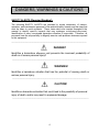
1
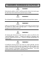
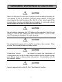
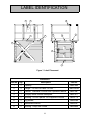
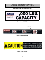
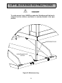
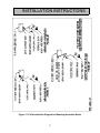
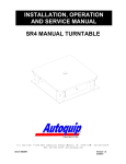
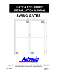
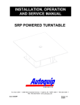
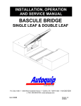
INSTALLATION, OPERATION
AND SERVICE MANUAL
CAROUSEL SCISSORS LIFT
P.O. Box 1058 • 1058 West Industrial Avenue • Guthrie, OK 73044-1058
5200 • FAX: 405-282-8105 • www.autoquip.com
Item # 830 CAR
• 405-282-
Version 1.0
09/2001
TABLE OF CONTENTS
Identification and Inspection
3
Dangers, Warnings, and Cautions
4
Label Identification
8
Specifications
12
Lift Blocking Instructions
13
Installation Instructions
15
Operating Instructions
18
Routine Maintenance
19
General Maintenance
21
Replacement Parts List
33
Troubleshooting Analysis
37
IMPORTANT
Please read and understand this manual prior to installation or operation of this lift.
Failure to do so could lead to property damage and/or serious personal injury. If
questions arise, call a local representative or Autoquip Corporation at 1-888-811-9876
or 405-282-5200.
PLANNED MAINTENANCE PROGRAM
A local Autoquip representative provides a Planned Maintenance Program (PMP) for
this equipment using factory-trained personnel. Call a local representative or Autoquip
Corporation at 1-888-811-9876 or 405-282-5200 for more information.
2
IDENTIFICATION & INSPECTION
IDENTIFICATION
When ordering parts or requesting information or service on this lift, PLEASE REFER
TO THE MODEL AND SERIAL NUMBER. This information is on a nameplate attached
to the leg assembly. Replacement parts are available from a local Autoquip distributor.
INSPECTION
Immediately upon receipt of the lift, a visual inspection should be made to determine
that the lift has not been damaged in transit. Any damage found must be noted on the
delivery receipt. In addition to this preliminary inspection, the lift should be carefully
inspected for concealed damage. Any concealed damage found that was not noted on
the delivery receipt should be reported in writing to the delivering carrier within 48 hours.
The following is a checklist that will aid in the inspection of the lift.
1. Examine entire unit for any signs of mishandling. Pay special attention to the power
unit and controls.
2. Thoroughly examine all connections, making sure they have not vibrated loose
during transit.
3. After installation, raise the lift and inspect the base frame and scissors assembly.
3
DANGERS, WARNINGS & CAUTIONS
SAFETY ALERTS (Required Reading!)
The following SAFETY ALERTS are intended to create awareness of owners,
operators, and maintenance personnel of the potential safety hazards and the steps that
must be taken to avoid accidents. These same alerts are inserted throughout this
manual to identify specific hazards that may endanger uninformed personnel.
Identification of every conceivable hazardous situation is impossible. Therefore, all
personnel have the responsibility to diligently exercise safe practices whenever exposed
to this equipment.
____________________________________________________________
DANGER!
Identifies a hazardous situation that presents the imminent probability of
death or of severe personal injury!!
_____________________________________________________________
WARNING!
Identifies a hazardous situation that has the potential of causing death or
serious personal injury.
_____________________________________________________________
CAUTION!
Identifies a hazardous situation that could lead to the possibility of personal
injury of death, and/or may result in equipment damage.
_____________________________________________________________
4
DANGERS, WARNINGS & CAUTIONS
Read and understand this manual and all labels prior to operating or servicing the
lift. All labels are provided in accordance with ANSI Z535.4.
DANGER!
Do not work under lift without maintenance device! To avoid personal
injury, NEVER go under the lift platform until the load is removed and the
scissors mechanism is securely blocked in the open position. See "Lift
Blocking Instructions" section.
DANGER!
To avoid personal injury, stand clear of scissors leg mechanism while lift is
in motion.
DANGER!
HIGH VOLTAGE!! Disconnect and/or lock out the electrical supply to the
power unit prior to any maintenance being performed.
DANGER!
Do not attempt to remove the velocity fuse until the maintenance leg
securely supports the lift and all hydraulic pressure has been removed from
the lifting cylinders and hydraulic hoses. Failure to do so could results in
personal injury or death!
5
DANGERS, WARNINGS & CAUTIONS
DANGER!
Extending the platform length or width beyond the factory limit could cause
the unit to tip, which could result in personal injury or death.
WARNING!
Do not operate this equipment without handrails and snap chains in place.
WARNING!
Under no circumstances should the speed control orifice be removed from
the Deltatrol to obtain faster lowering speed. A loaded lift can reach
dangerous and destructive speed!!
WARNING!
All warning and information decals should be in place as outlined in the
“Label Identification” section. If decals are missing or damaged, they
should be replaced with new ones. Contact an Autoquip representative for
replacements.
WARNING!
Lift platforms traveling below floor levels my create openings, and the
shape of the load and how the load is arranged on the lift may create a toe
hazard as the load passes the top edge of the pit. Both situations may
require guarding in accordance with Federal Regulations. Any such
guarding must be installed prior to operating the lift.
6
DANGERS, WARNINGS & CAUTIONS
CAUTION!
Never run the pump for more than a couple of seconds without pumping oil.
This applies to low oil conditions, improper motor rotation, running the
pump against the relief pressure after the lift is fully raised against the
physical stops, running overloaded beyond capacity, or running at reduced
speed because of pinched or obstructed hydraulic lines.
CAUTION!
Do not continue to depress the “UP” button on the controller if the lift is not
raising or if the lift has reached the fully raised position. To do so may
result in permanent damage to the motor or pump.
CAUTION!
Do not operate the power unit on relief for more than a few seconds. When
on relief, the valve will make a squealing sound.
CAUTION!
Precautions should
be taken to prevent the introduction of
contaminates such as dirt or other foreign material into the system through
open fittings, pipes or disassembled components. Contamination will ruin
the hydraulic system.
CAUTION!
Use only approved oils in the lift. See “Specifications” section.
7
LABEL IDENTIFICATION
5
8
5
1
3
2
6
2
4
7
6
Figure 1 Label Placement
CAROUSEL
Item No.
Qty
Description
Part No.
1
2
Capacity
2
4
Danger – Do Not Put Hands Or Feet . . .
3
2
Caution: Familiarize Yourself With Operators Manual
36401487
4
1
Autoquip Serial Number Nameplate
36401511
5
2
Warning: Do Not Operate This Equipment Without . . .
36403715
6
2
Leg Socket
36400265
7
1
Maintenance Device
36400257
8
2
Warning: Keep Gate Closed . . .
36403699
36401594
8
36430050M
LABEL IDENTIFICATION
Note: Labels shown here are not actual size.
Figure 2 Label 36401594
CUT LINE
Figure 3 Label 36430050M
Figure 4 Label 36401487
9
LABEL IDENTIFICATION
Figure 5 Label 36401511
Figure 6 Label 36403715
Figure 7 Label 36400265
10
LABEL IDENTIFICATION
Figure 8 Label 36400257
Figure 9 Label 36403699
11
SPECIFICATIONS
Model
Lowered
Height
(inches)
Travel
(inches)
Lift
Cap
(lbs)
Side
Load
Cap
(lbs)
End
Load
Cap
(lbs)
Base
Size
(inches)
Std.
Minimum
Platform
Size
(inches)
Max
Allowable
Platform
Size
(inches)
Lift
Weight
(lbs)
7220
8
72
2,000
1,000
500
58 X 96
72 X 102
72 X 168
4,000
8420
8
80
2,000
1,000
500
58 X 111
72 X 120
72 X 168
4,300
9620
12
96
2,000
1,000
500
58 X 140
72 X 144
72 X 168
4,500
NOTE: All models travel a speed of 20 fpm.
LOAD CAPACITY
The load capacity rating is stamped on a metal plate attached to one side of the lift.
This figure is a net capacity rating for a lift furnished with the standard platform. The
relief valve of the pumping unit has been set to raise the weight, plus a small amount for
overload. Where equipment, special attachments, etc, are installed on the lift after
leaving the plant, deduct the weight of these from the load rating to obtain the net
capacity. Lifts should not be overloaded beyond the established capacity as
damage and/or personal injury may result.
UNBALANCED LOADING
The stabilization provided is basically for balanced loads. If special attachments extend
beyond the length and/or width dimensions of the platform, the end and/or side load
capacity must be reduced (contact an Autoquip Sales representative).
PUMP PRESSURE
This lift incorporates a positive displacement pump machined to a high degree of
accuracy and specially adapted to requirements of higher-pressure ranges over that of
a standard pump. Standard factory models of the same manufacture cannot replace it.
The pump can operate efficiently at intermittent pressures up to 3200 PSI and
continuous duty to 2500 PSI. However, the safety relief valve in the power unit is
factory-set considerably below 3,200 psi to stay within the parameters of the maximum
lifting capacity.
12
LIFT BLOCKING INSTRUCTIONS
1. Remove all load from the platform. Never block the lift when loaded, only when
empty.
2. Raise the lift platform fully by depressing the “UP” button.
3. The maintenance leg is stored on the clevis end of the lift. Place the end of the
maintenance leg in the socket on the base frame of the lift.
4. Begin lowering the platform by activating the “DOWN” valve until the scissors
mechanism is resting on the maintenance leg. Continue activating the “DOWN” valve
five to ten seconds to relieve the pressure in the line.
5. Check to be certain that the maintenance leg is securely in the socket on the platform
and the socket on the base frame.
DANGER!
HIGH VOLTAGE!! – Disconnect and/or lock out the electrical supply to the
power unit prior to any installation or maintenance being performed.
6. To remove the maintenance leg, raise the platform by activating the “UP” valve to
provide sufficient clearance for the removal and storage of the maintenance leg.
13
LIFT BLOCKING INSTRUCTIONS
DANGER!
To avoid personal injury, NEVER go under the lift platform until the load is
removed and the scissors mechanism is securely blocked in the open
position.
MAINTENANCE LEG
MAINTENANCE LEG
SOCKET
Figure 10 Maintenance Leg
14
INSTALLATION INSTRUCTIONS
1. The surface area where the lift will be set must be flat and level and be of sound
concrete of sufficient thickness to support the lift while loaded at full capacity.
2. For beveled toe guard models, the surface area must have a recess to allow
hydraulic lines to pass under the ends of the base frame. Hydraulic lines must be
protected or placed in a way that they are free from possible damage.
3. The base of the lift must be lagged down in the holes provided. Lag bolts should be
able to withstand 2000 lbs. minimum upward pull at each corner.
4. Shims and/or grout may be required to insure support of the entire base frame and
platform support members. DO NOT “spot” shim! Shims and/or grout must be able
to support the lift while loaded at full capacity.
5. Optional floor ramps are available. Consult a local Autoquip dealer.
15
INSTALLATION INSTRUCTIONS
PROCEDURE FOR A LIFT ORDERED WITH AN ACCORDION SKIRT
1. Position the platform in the raised position. Install the maintenance locks (see “Lift
Blocking Instructions” section). Position the accordion with the weight rod pocket at
the bottom and the mounting collar at the top. The breathable material when
provided must be positioned at the top of the skirt with the mounting collar.
2. Slip the skirt over the end of the platform. Turn the skirt as required to slide over the
other end of the platform and leg assembly. The skirt should be in position under
the platform while enveloping the base assembly.
3. See Figure 11 and select the correct mounting configuration (Number 1, 2, or 3).
Figure #1: Mounting an Accordion Skirt Onto the Platform Side
Raise one side of the skirt along with a skirt -mounting bar (1/8” x 1”) to (1) side
of the platform. When possible, center the skirt-mounting collar and skirtmounting bar (1/8” x 1”) on the platform side. Align the pre-drilled holes in the
side of the platform with the skirt-mounting bar holes and punch holes in the skirtmounting collar. Push a nylon drive rivet through each hole in the skirt-mounting
bar. Hammer the aluminum pin into the rivet until flush with the rivet head.
Repeat mounting process for the remaining sides of the accordion skirt.
Figure #2: Mounting an Accordion Skirt Underneath the Platform
Raise one side of the skirt along with a skirt-mounting bar (1/8" x 1") to the
underside of the platform skirt support bar. When possible, center the skirt
mounting collar and the skirt-mounting bar (1/8” x 1”) on the platform support bar.
Align the pre-drilled holes in the skirt support bar (picture frame) with the skirt mounting bar holes and punch holes in the skirt-mounting collar. Push a nylon
drive rivet through each hole in the skirt-mounting bar. Hammer the aluminum
pin into the rivet until flush with the rivet head. Repeat mounting process for the
remaining sides of the accordion skirt.
Figure #3: Mounting an Accordion Skirt Onto the Bevel Toe Guard
Raise one side of the skirt along with a skirt-mounting bar (1/8” x 1”) to the side
of the bevel toe guard. When possible, center the skirt mounting collar and the
skirt-mounting bar (1/8” x1”) on the platform bevel toe guard. Align the pre-drilled
holes in the bevel toe guard with the skirt-mounting bar holes and punch holes in
the skirt-mounting collar. Push a nylon drive rivet through each hole in the skirtmounting bar. Hammer the aluminum pin into the rivet until flush with the rivet
head. Repeat mounting process for the remaining sides of the accordion skirt.
4. Install weight rods into the weight rod pockets at the bottom of the accordion skirt.
Install the spring tempered wire rods into the pocket of black convolutions.
16
INSTALLATION INSTRUCTIONS
Figure 11 Field Installation Diagram for Mounting Accordion Skirts
17
OPERATING INSTRUCTIONS
Familiarize yourself with this operator’s manual before operating the equipment!!!
1. Scissors lifts have maximum lifting capacity ratings (see “Specifications” section).
The safety relief valve has been factory set to open at a pressure slightly above the
rated load capacity and allows the oil to bypass into the reservoir to prevent damage
to the lift and its hydraulic power unit. The safety relief valve should not be
adjusted for any reason as it could cause the motor to prematurely burn out.
Applying loads exceeding the rated capacity of the lift may result in excessive wear
and damage to the lift.
2. This type of lift is designed primarily for carousel picking applications and is typically
furnished with constant pressure pushbutton controls. Actuating the "UP" button will
cause oil to enter the cylinders and the lift will rise.
3. When the desired height or upward travel of the platform is attained, removing
pressure from the switch deactivates the “UP” circuit button. The oil stops flowing
and the upward movement will stop.
4. Activate the "DOWN" button to lower the lift. Opening the down control valve allows
the oil in the cylinders to flow through the down valve at a controlled rate and return
oil to the reservoir.
5. When the desired height or downward travel of the platform is attained, removing
the operator’s foot or hand from the switch deactivates the “DOWN” circuit. The oil
stops flowing from the cylinders and the downward movement will stop.
CAUTION!
Do not continue to activate the "UP" button if the lift is not raising or if it
has reached the fully raised position. To do so may result in permanent
damage to the lift.
CAUTION!
Do not operate the power unit on relief for more than a few seconds. When
on relief, the valve will make an audible squealing sound.
18
ROUTINE MAINTENANCE
Normally scissors lifts will require very little maintenance. However, a routine
maintenance program could prevent costly replacement of parts and/or downtime.
WARNING!
To avoid personal injury, NEVER go under the lift platform or perform any
maintenance on the lift until the load is removed and the scissors
mechanism is securely blocked in the open position. See "Lift Blocking
Instructions" section.
MONTHLY INSPECTION:
1. Check oil level (see oil recommendations in this section) and add appropriate oil
when necessary.
2. Check for any visible leaks. Correct as necessary.
3. Check any unusual noise when it occurs. Determine the source and correct as
necessary.
4. Check the snap rings at all rollers, if not in place, and/or secure, replace or repair
immediately.
5. Check all rollers for signs of wear. Replace as necessary.
6. Do not grease roller or axles; they have lifetime-lubricated bearings.
7. Check all wiring for looseness or wear. Repair at once.
OIL REQUIREMENTS:
Change oil yearly, or more frequently if it darkens materially or feels gummy or gritty.
Use detergent motor oils only. Do not use hydraulic-jack oil, hydraulic fluids, brake
fluids, or automatic transmission fluid.
19
ROUTINE MAINTENANCE
Oil Viscosity Recommendations
Environment (Ambient Temperatures)
Recommended Oil
Indoor location, variable temperatures
(30 - 100° F)
10W30 or 10W40 Multiviscosity motor oil
Indoor location, consistent temperatures
(70° F)
SAE-20W motor oil
Outdoor location, (-10 - 100° F)
SAE 5W30 Multiviscosity motor oil
Cold-storage warehouse (10 - 40° F)
5W30 Multiviscosity motor oil
Freezer (-40° F to 0° F)
Consult Factory
OIL CAPACITY:
Reservoir capacity for the steel “vertical” tank is approximately 11 gallons.
The oil level in the reservoir should be 1” to 1 _” below the top of the reservoir with the
lift in the fully lowered position.
PIPE THREAD SEALANT
Loctite PST #567 pipe thread sealant or equivalent is recommended. Do not use
Teflon tape. Tape fragments can cause malfunctioning of the hydraulic system.
20
GENERAL MAINTENANCE
1. Change oil once a year or when it materially darkens or feels gritty. Also, check oil
for the presence of water (oil will turn milky in color.)
2. NEVER TRY TO DISASSEMBLE OR REPAIR A PUMP IN THE FIELD. These
pumps are high-precision devices requiring extreme precision in fit-up. When one is
damaged, there is seldom anything that can be repaired in the field. It is also more
economical to replace a pump than to refit old parts with new parts.
3. The pin, or roller bushing should be replaced whenever excessive wear is detected.
The rollers are furnished with the pressed-in bushing as a unit part.
DANGER!
To avoid personal injury, NEVER go under the lift platform until the load is
removed and the scissors mechanism is securely blocked in the open
position.
POWER UNIT
DANGER!
HIGH VOLTAGE!! Disconnect and/or lock out the electrical supply to the
power unit prior to any maintenance being performed.
1. The “vertical” unit utilizes a heave duty 5 HP/208, 230, or 460 Volts/60 hertz/3 phase
motor coupled to a high-pressure positive displacement gear pump, and Autoquip
Corporation’s patented Deltatrol valve assembly. It is also available with a 5 HP/115
or 230 Volts/60 hertz/single-phase motor as an option.
2. The following should be referenced in connecting the standard heavy-duty motors to
power sources. Remember that heavy wire must be used all the way to the power
source.
Power Unit
115 Volts
208 Volts
230 Volts
460 Volts
Standard Three Phase
N/A
16 AMPS
15.2 AMPS
7.6 AMPS
Standard Single Phase
58 AMPS
N/A
24.5 AMPS
N/A
NOTE: All amperage draws shown are full-load amperages.
21
GENERAL MAINTENANCE
CYLINDER REMOVAL AND REPACKING (see figure 12)
1.
Raise the lift to its full height and block securely. See “Lift Blocking Instructions”.
2.
Loosen and remove the cylinder hose at the hose union in the tee connection
between the two cylinders. Place the open end of the hose in a container to
receive oil spillage.
3.
Remove the pin retaining screw in the cylinder clevis or pin retaining rings, and
carefully tap out the clevis pin to avoid damaging the clevis pin bushings.
4.
Remove the cylinder from the lift.
5.
Push the piston rod into the tube to eject as much oil as possible into a container.
6.
Pull the rod out of the cylinder tube sufficiently to gain access to the face spanner
wrench holes on the rod end of the cylinder. Do not allow oil or dirt to be pulled
back into the hydraulic hose.
7.
Using a face spanner wrench, turn the bearing assembly clockwise until the tip of
the retainer appears in the slot in the outer surface of the cylinder tube.
8.
Insert a small blade screwdriver under the tip of the retainer and turn the bearing
assembly counter-clockwise until the retainer is free of the slot.
NOTE: The wire retainer may be a cutting or puncturing hazard.
9.
Pull the rod out of the tube slowly to remove the rod and bearing assembly.
NOTE: Use caution to prevent surface damage to the rod. This could result in
seal failure and/or leakage.
10. Inspect the bore of the tube. Hone if necessary to remove any surface
imperfections in the bore. Flush thoroughly after honing to remove chips and grit.
11. Remove the piston lock nut and slide off the piston and bearing assembly. Take
care to protect the rod surface from damage.
12. Install new packing and seals on the piston, rod, and bearing assembly. Inspect all
grooves and seal surfaces for any imperfections and repair or replace as
necessary.
13. Grease all seals and packing liberally and install the bearing assembly and the
piston on the rod and torque the lock nut to 500 ft. lbs.
22
GENERAL MAINTENANCE
14. Install the rod into the tube using care not to damage any seals or packing
15. Align the retainer hole in the bearing assembly groove with the slot in the tube.
16. Insert the retainer hook end in the hole/slot and using a face spanner wrench, turn
the bearing assembly clockwise until the retainer is completely inserted in the
groove/slot in the tube.
17. Check the clevis pin bushings in the cylinder rod for wear and replace as
necessary.
18. Install the assembled cylinder into the lift by carefully driving the clevis pin through
the clevis and cylinder rod. Extreme care must be taken to prevent damage to the
clevis in the bushings. Install the pin retaining screw with washers, engaging the
slot in the pin, and torque to 25 ft. lbs. or the retaining rings and washers on the pin
(cylinder rod may be extended by hand.)
19. Connect the cylinder hydraulic hose and the tee using the recommended sealant.
20. Check all pins and other mechanical as well as hydraulic components to assure
that the assembly is complete and in good working order.
21. Turn the electrical supply back on and press the “UP” button on the controller to
raise the lift. NOTE: 15 to 30 seconds time may elapse to fill the empty cylinders
before movement is noted.
22. Remove and place the maintenance leg in its storage location, then press the
“DOWN” button on the controller to cycle the lift to the fully lowered position. Hold
the “DOWN” button 30 to 40 seconds to allow air in the cylinders to bleed back into
the reservoir tank.
23. Cycle the lift 10 to 15 times and repeat the bleeding operation by holding the
”DOWN” button for 30 to 40 seconds.
24. Check the oil level in the reservoir with the lift in the fully lowered position. Add as
necessary (see “Routine Maintenance” for oil recommendations).
25. Clean the oil filler breather cap if it appears dirty.
26. Clean up any debris and or spilled oil from the area.
NOTE: Depending on experience, the job should take one to two hours.
23
GENERAL MAINTENANCE
Figure 12 Hydraulic Cylinder
24
GENERAL MAINTENANCE
VELOCITY FUSE REPLACEMENT
DANGER!
Do not attempt to remove the velocity fuse until the lift is securely
supported with the maintenance locking devices and all hydraulic pressure
has been removed from the lifting cylinders and hydraulic hoses. Failure
to follow these instructions could result in personal injury or death!
Never attempt to take a velocity fuse apart and repair it. These are precision devices
that are factory assembled under exacting conditions. Velocity fuses should always be
replaced.
1.
The arrow on the exterior surface of the velocity fuse shows the direction of the
restriction to the oil flow. The arrow should always point away from the cylinder.
2.
Do not use Teflon tape on the threaded connections of a velocity fuse. Tape
fragments can cause malfunctioning of the fuse.
3.
Check all fitting connections for hydraulic leaks and tighten as necessary.
HOSE ORIENTATION
To prevent damage to the cylinder hose and possible failure of lift, it is necessary to
establish a correct hose shape and pattern of movement as follows:
1.
Raise the lift to its full height and block securely. See “Lift Blocking Instructions”.
2.
Install one end of the new hose to the cylinder elbow fitting.
3.
Since the hose is fixed at both ends, it is possible to put a twist in the hose that will
allow it to describe the same pattern each time the lift is operated. This twist will
allow the hose to travel about half way between the cylinder on the right side and
the inner leg on the right side.
4.
Lower the lift carefully and check to see that the hose is free and clear of the
cylinder and the inner leg assembly. If not, twist the hose in the direction
necessary to clear it of any obstruction and then lock the swivel fitting securely.
25
M
26
SUCTION
LINE
RELIEF
VALVE
SUCTION LINE FILTER IS INTERNAL
TO DELTATROL BLOCK UNLESS A
SEPERATE FILTER IS SPECIFIED.
FILTER
P.F.
CHECK VALVE
RESERVOIR
DOWN SPEED
RESTRICTOR
RETURN
LINE FILTER
LOWERING VALVE AND PRESSURE LINE FILTRATION.
COMPENSATED FLOW CONTROL, SOLENOID
DELTATROL VALVE PROVIDES COMPLETE,
THE FUNCTION OF CHECK, RELIEF, PRESSURE
PRESSURE LINE
VELOCITY FUSES
(1) VELOCITY FUSE PER CYLINDER.
QUANTITY OF CYLINDERS AND
VELOCITY FUSES DEPENDS ON
MODEL OF LIFT USED.
LIFTING
CYLINDERS
GENERAL MAINTENANCE
Figure 13 Hydraulic Schematic – Vertical Power Unit
GENERAL MAINTENANCE
Figure 14 Electrical Schematic – 208-230-460 Volt Three Phase
27
GENERAL MAINTENANCE
Figure 15 Electrical Schematic 230 V/1PH
28
GENERAL MAINTENANCE
Figure 16 Electro-Hydraulic Schematic – Soft Start/Soft Stop Option
29
GENERAL MAINTENANCE
Figure 17 Uptravel Limit Switch Location
30
GENERAL MAINTENANCE
Figure 18 – Gate Interlock Limit Switch Location
31
7/16" HOLE DRILLED IN
PLATFORM AT LOCATION
OF LOCKING PIN. SEE
PLATFORM DRAWING.
"A"
2
1/8"
1/8"
ITEMS #2 THRU #9
NOT SHOWN IN THIS
VIEW FOR CLARITY.
UNDERSIDE OF
PLATFORM (REF.)
1
1
VIEW "A-A"
4 5
"A"
UNDERSIDE OF
PLATFORM (REF.)
MOUNTING BRACKET LOCATION DETAIL
3"
3
2-1/2"
3" (REF.)
19/32"
C
3"
<2T
APPROXIMATE WEIGHT:
REFERENCE DWG.
1
DATE:
DRAWING TITLE
NO.
5
4
3
2
6
JOB NAME:
ITEMS #6 THRU #9 NOT SHOWN.
1 of 1
PAGE:
REV.
6
TOLERANCES UNLESS
OTHERWISE SPECIFIED:
BY
SIZE
AQJ NO.
DATE
+/- 1/32
FRACTIONS:
DECIMALS:
ONE PLACE
.X +/- .1
TWO PLACE
.XX +/- .03
THREE PLACE .XXX +/- .010
+/- 1/2~
ANGLES:
BREAK ALL SHARP EDGES:
.010 MAX. x 45~ CHAMFER
351-0192-2
DRAWING NUMBER:
REVISIONS
LIMIT SWITCH TO BE MOUNTED UNDER PLATFORM
TO SENSE THE GATE LOCKING PIN. SWITCH TO
BE WIRED NORMALLY OPEN HELD CLOSED (BY THE
PIN) AND WIRED TO THE J-BOX ON THE LEG
OR PLATFORM.
This drawing is the sole
property of Autoquip Corp.
and cannot be used for
design & construction
without permission
of Autoquip Corp.
1997
2.
1.
ITEM #1 DETAIL
3-1/2"
2-11/32"
(4) #10-24 TAPPED HOLES.
(1) REQUIRED PER LIFT
NOTE:
THIS EDGE TO BE WELDED
TO UNDERNEATH SIDE OF
PLATFORM.
7/16"
C
1/8"
32
2"
1" (REF.)
4
2
UP SLOW LIMIT
SWITCH ACTUATOR
BAR.
2
2
BASE CLEVIS
UP-SLOW LIMIT
SWITCH ACTUATOR
BAR.
11
11
BASE FRAME
2
2
5
3
9"
6 7
2"
1
6 7
4
3
1-1/4"
6" (REF.)
1/8"
Figure 19 – Limit Switch Location – Soft Start/Soft Stop
ITEMS #4 THRU #10
NOT SHOWN THIS VIEW.
8"
MAINTENANCE LEG
STORAGE SOCKET.
SEE BASE FRAME
DWG. FOR LOCATION.
UP SLOW LIMIT
SWITCH MOUNTING
PLATE.
1
2
3/4"
2
1/8"
1/8"
4" (REF.)
1
1"-3"
1"-3"
C
<2T
APPROXIMATE WEIGHT:
REFERENCE DWG.
DATE:
DRAWING TITLE
JOB NAME:
NO.
1
2
1 of 1
PAGE:
REV.
ITEM #10, 6" X 6" X 6" ELECTRICAL
ENCLOSURE, TO REPLACE 4" X 4" X 2"
J-BOX ON OPPOSITE LEG SET.
3.
4
3
DOWN-SLOW LIMIT SWITCH TO BE
SET FOR LAST 12" OF DOWN TRAVEL.
UP-SLOW LIMIT SWITCH TO BE
SET FOR LAST 12" OF UP TRAVEL.
2.
1.
This drawing is the sole
property of Autoquip Corp.
and cannot be used for
design & construction
without permission
of Autoquip Corp.
1997
DOWN SLOW LIMIT
SWITCH ACTUATOR
PLATE.
TYP.
INNER LEG
3
DOWN SLOW LIMIT
SWITCH MOUNTING
PLATE.
3
6 7
5 3
"DOWN-SLOW" LIMIT SWITCH
1
SECTION "A-A"
ITEMS #8 THRU #10
NOT SHOWN THIS VIEW.
4 3
INNER LEG
UP-SLOW LIMIT SWITCH
BASE CLEVIS
BASE FRAME
2
2
2
2
4
BY
DATE
SIZE
AQJ NO.
351-0209-4
DRAWING NUMBER:
REVISIONS
TOLERANCES UNLESS
OTHERWISE SPECIFIED:
+/- 1/32
FRACTIONS:
DECIMALS:
.X +/- .1
ONE PLACE
.XX +/- .03
TWO PLACE
THREE PLACE .XXX +/- .010
+/- 1/2~
ANGLES:
BREAK ALL SHARP EDGES:
.010 MAX. x 45~ CHAMFER
C
GENERAL MAINTENANCE
REPLACEMENT PARTS LIST
LEG ASSEMBLY PARTS LIST
QTY
Part No.
Description
4
Pin, leg clevis, 1 1/8” x 2” long
52502705
4
Pin, leg clevis, 1 1/2” x 2 15/16” long w/2-ring grooves
4
Bushing, 1 1/8” ID x 1” long
20022877
2
Bushing, 1 1/2” ID x 2” long
20024006
2
Washer, 1/8” TK x 1 _” ID x 2 _” OD, steel
24024507
2
Retaining Ring, 1 _” heavy duty
45400249
4
Washer, 1/8” TK x 1 _” ID x 2 _” OD, plastic
24094518
4
Washer, 5/16” STD steel
24050163
2
Cap Screw, 3/8” – 16 x 1” long
22031132
2
Pin, Cylinder Clevis, 1 1/8” x 7” long w/ 1 ring groove
52502440
2
Pin, Cylinder Clevis, 1 1/8” dia x 4 _” long w/2 ring grooves
52500196
4
Washer, 1/16” TK x 1 1/8” ID x 2” OD, plastic
24092306
4
Roller w/ Bushing, _” TK x 1 1/8” ID x 3” OD
52600269
4
Washer, 1/16” TK x 1 1/8” ID x 2” OD, steel
24012353
4
Pin, Leg Roller, 1 1/8” dia x 2 3/32” long w/1 ring groove
52502432
4
Retaining Ring, Leg Roller Pin, 1 1/8”
45400082
8
Washer, 1/16” TK x 1 1/8” ID x 2” OD, plastic
24092306
2
Pin, Inner Leg Roller, 1 _” dia x 2 7/8” long
33
N/A
N/A
REPLACEMENT PARTS LIST
POWER UNIT PARTS LIST
QTY
1
Description
Part No.
1
Motor, 5 HP 208/230/460 Volt 3 PH straight shaft
30600449
1
Motor Coupling, Lovejoy L-095, 1 1/8” bore
20000154
1
Pump Coupling, Lovejoy L-095, 7/16” bore
20000030
1
Coupling Rubber Spider
20000162
1
Pump, 2.25 GPM with straight shaft
40300162
2
_” Dyna-Seal Washer for Deltatrol
45901014
1
Return Pipe Assembly, 6” long
41050485
1
Sump Strainer
47700075
1
Hose, Pump to Deltatrol, 3/8” x 18” long w/ 1 swivel
46100020
1
Deltatrol Kit
41050880
1
Down Solenoid, 24 volt
32701380
1
Down Solenoid, 115 Volt
32701370
1
Filler/Breather Cap Assembly
47700208
1
Oil Reservoir, 16” x 16” x 10”
64000813
1
Control Panel, 460 VAC/24 VAC controls
35150081
1
Control Panel, 208-230 VAC/24 VAC controls
35150080
1
Control Signal; Pushbutton – “UP”/”DOWN”
36201820
1
Dump Valve, Soft Start/Soft Stop
41302480
Flow Control, soft start/soft stop
41502626
34
REPLACEMENT PARTS LIST
Figure 20 Vertical Power Unit Parts Detail
35
REPLACEMENT PARTS LIST
HYDRAULIC PARTS LIST
ITEM
No.
QTY
Description
Part No.
72” & 84”
Travel
Models
Part No.
96” Travel
Models
1
2
Cylinder, 3 _” bore x 11 _” stroke
42400731
N/A
1A
2
Packing Set for Single Cylinder (for part # 42400731)
45503070
N/A
Packing Set for Single Cylinder (for part # 42700831)
N/A
45503170
2
2
Hydraulic elbow, _” MP – _” MP
26100370
26100370
3
2
Velocity Fuse
41800558
41800558
4
1
Hydraulic Hose, _” x 24” long w/ swivel one end only
46000490
46000490
5
1
Hydraulic Hose, _” x 9” long w/ swivel one end only
46000022
46000022
6
1
Hex Reducer Bushing, 3/8” to _”
26300103
26300103
7
1
Hydraulic Tee, 3 way 3/8” FP
26150102
26150102
8
1
Hydraulic Hose, 3/8” with swivel one end only
46100095
46100103
9
1
Hex Reducer Bushing, _” to 3/8”
26305086
26305086
10
1
Pipe Elbow 90°, _” NPT
25070251
N/A
N/A
25380080
52200029
N/A
Reducer Coupling, _” to 3/8”
11
1
Hose Clamp Set
Cylinder, 4” bore x 15 7/16” stroke
N/A
36
42700831
Figure 21 Hydraulic Parts Detail
37
TROUBLESHOOTING ANALYSIS
DANGER!
To avoid personal injury, NEVER go under the lift platform until the load is
removed and the scissors mechanism is securely blocked in the open position.
See "Lift Blocking Instructions" section.
PROBLEM
POSSIBLE CAUSE AND SOLUTION
Lift does not raise.
• The motor voltage/wiring may be incorrect.
• The hydraulic line or hose may be leaking.
• Oil in the reservoir may be low. Add oil as
necessary (See the “Routine Maintenance”
section.)
• The load may exceed the rating. (See the
“Specifications” section.)
• The suction screen may be clogged. Remove
and clean the screen. Drain and replace the oil.
• The suction line may be leaking air due to a
loose fitting. Tighten as needed.
• The breather holes in the reservoir fill plug may
be clogged. Remove and clean.
• The "Down" valve may be energized by faulty
wiring or stuck open. Remove the solenoid and
check.
• The power unit pump may be defective
• The structural members of the lift may be in a
bind.
• The manual lowering device may be engaged.
Lift seems bouncy during
operation.
• There may be air in the hydraulic system.
Bleed the air from the cylinder
• Oil in the reservoir may be low. Add oil as
necessary (See the “Routine Maintenance”
section.)
• The power unit suction strainer may be clogged.
• The power unit suction line may be leaking.
• There may be foreign material on the roller
plate.
38
TROUBLESHOOTING ANALYSIS
PROBLEM
Lift will not lower.
POSSIBLE CAUSE AND SOLUTION
The down solenoid may be malfunctioning.
The maintenance leg could be installed.
The structural members may be in a bind.
The tubing or hose is obstructed or broken. Check
for obstruction in the line.
• The return filter may be clogged.
• The velocity fuse may be locked. Do not attempt to
remove the velocity fuse. The following steps
should be followed:
•
•
•
•
1. Remove the load from the lift. Inspect all fittings,
hoses, and other hydraulic components for leads or
damage.
2. If no leak or damage is noticed, attempt to
pressurize the lifting cylinder by depressing the “UP”
button on the controller for a few seconds.
Immediately up releasing the “UP” button, depress
the “DOWN” button. If the lift starts to lower, continue
pressing the “DOWN” button until the lift is in the fully
lowered position.
3. If the lift does not lower after trying Step 2, wait
approximately 10 – 15 minutes for the pressure in the
hydraulic system to equalize. Then, depress the
“DOWN” button until the lift is in the fully lowered
position.
4. Once the lift is in the fully lowered position, bleed
the air from the hydraulic system by depressing the
“DOWN” button. Hold the “DOWN” button for
approximately 60 seconds. This step may need to be
repeated several times to fully remove the air in the
system by raising the lift to 50% of its travel and then
lowering it.
• Should the above steps not correct the problem,
contact Autoquip to obtain instruction for further
action.
39
TROUBLESHOOTING ANALYSIS
PROBLEM
Lift raises slowly.
POSSIBLE CAUSE AND SOLUTION
• The structural members of the lift may be binding.
• The tubing or hose is obstructed or broken. Where
pipe is used, check for obstruction in the line.
• The hydraulic line or hose may be leaking.
• The oil viscosity is not suited for the environmental
conditions. Refer to “Routine Maintenance” section
for oil recommendations.
• Check the oil level in the reservoir.
• The motor voltage/wiring may be incorrect.
• The suction screen may be clogged. Remove and
clean the screen. Drain and replace the oil.
• The suction line may be leaking air due to a loose
fitting. Tighten as needed.
• The breather holes in the reservoir fill plug may be
clogged. Remove and clean.
• The power unit pump may be defective.
Lift lowers slowly.
• The structural members of the lift are binding.
• The tubing or hose is obstructed or broken. Where
pipe is used, check for obstruction in the line.
• The oil viscosity is not suited for the environmental
conditions. Refer to “Routine Maintenance” section
for oil recommendations.
• The return filter may be clogged due to dirt or
damage.
40
TROUBLESHOOTING ANALYSIS
PROBLEM
Lift will not remain in
raised position.
POSSIBLE CAUSE AND SOLUTION
• The cylinder packing may be leaking.
• The pump or Deltatrol regulator is not seating.
• The pump or Deltatrol check valve is not seating.
• The hydraulic tubing, hose, or fitting is leaking oil.
•
The return filter may be clogged.
41