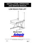
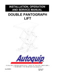
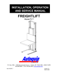
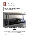
1
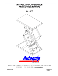
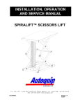
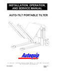
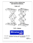
INSTALLATION, OPERATION
AND SERVICE MANUAL
CMD PORTABLE DOCK
SCISSORS LIFT
P.O. Box 1058
Item #830CMD
• 1058 West Industrial Avenue Guthrie,
•
OK 73044-1058
•
FAX: 405-282-8105 • www.autoquip.com
405-282-5200 •
Version 1.0
07/2001
TABLE OF CONTENTS
Identification and Inspection
3
Dangers, Warnings, and Cautions
4
Label Identification
8
Specifications
11
Lift Blocking Instructions
12
Installation Instructions
14
Operating Instructions
16
Routine Maintenance
18
General Maintenance
20
Replacement Parts List
27
Troubleshooting Analysis
28
IMPORTANT
Please read and understand this manual prior to installation or operation of this lift.
Failure to do so could lead to property damage and/or serious personal injury. If any
questions arise, call a local representative or Autoquip Corporation at 1-888-811-9876
or 405-282-5200.
PLANNED MAINTENANCE PROGRAM
A local Autoquip representative provides a Planned Maintenance Program (PMP) for
this equipment using factory-trained personnel. Call a local representative or Autoquip
Corporation at 1-888-811-9876 or 405-282-5200 for more information.
2
IDENTIFICATION & INSPECTION
IDENTIFICATION
When ordering parts or requesting information or service on this lift, PLEASE REFER
TO THE MODEL AND SERIAL NUMBER. This information is on a nameplate attached
to the leg assembly. Replacement parts are available from a local Autoquip distributor.
INSPECTION
Immediately upon receipt of the lift, a visual inspection should be made to determine
that it has not been damaged in transit. Any damage found must be noted on the
delivery receipt. In addition to this preliminary inspection, the lift should be carefully
inspected for concealed damage. Any concealed damage found that was not noted on
the delivery receipt should be reported in writing to the delivering carrier within 48 hours.
The following is a checklist that will aid you in the inspection of this lift:
1.
Examine entire unit for any signs of mishandling. Pay special attention to the
power unit and pushbuttons.
2.
Thoroughly examine all connections, making sure they have not vibrated loose
during transit, and inspect wiring for any signs of damage.
3.
After installation, raise the lift and inspect the base frame, platform, scissors
assembly, and cylinder plumbing connections.
3
DANGERS, WARNINGS & CAUTIONS
SAFETY ALERTS (Required Reading!)
The following SAFETY ALERTS are intended to create awareness of owners,
operators, and maintenance personnel of the potential safety hazards and the steps that
must be taken to avoid accidents. These same alerts are inserted throughout this
manual to identify specific hazards that may endanger uninformed personnel.
Identification of every conceivable hazardous situation is impossible. Therefore, all
personnel have the responsibility to diligently exercise safe practices whenever exposed
to this equipment.
____________________________________________________________
DANGER!
Identifies a hazardous situation that presents the imminent probability of
death or of severe personal injury!!
_____________________________________________________________
WARNING!
Identifies a hazardous situation that has the potential of causing death or
serious personal injury.
CAUTION!
Identifies a hazardous situation that could lead to the possibility of personal
injury of death, and/or may result in equipment damage.
_____________________________________________________________
4
DANGERS, WARNINGS & CAUTIONS
Read and understand this manual and all labels prior to operating or
servicing the lift. All labels are provided in accordance with ANSI
Z535.4.
DANGER!
Do not work under lift without maintenance device! To avoid personal
injury, NEVER go under the lift platform until the load is removed and the
scissors mechanism is securely blocked in the open position. See "Lift
Blocking Instructions" section.
DANGER!
To avoid personal injury, stand clear of scissors leg mechanism while lift is
in motion.
DANGER!
Do not install the lift in a pit unless it has a bevel toe guard or other
approved toe protection. A shear point can exist which can cause severe
injury to the foot.
DANGER!
HIGH VOLTAGE!! Disconnect and/or lock out the electrical supply to the
power unit prior to any maintenance being performed.
5
DANGERS, WARNINGS & CAUTIONS
DANGER!
Extending the platform length or width beyond the factory limit could cause
the unit to tip, which could result in personal injury or death.
DANGER!
Do not attempt to remove the velocity fuse until the maintenance locks
securely support the lift and all hydraulic pressure has been removed from
the lifting cylinders and hydraulic hoses. Failure to do so could result in
personal injury or death!
WARNING!
Do not operate this equipment without handrails, stanchion, and snap
chains in place.
WARNING!
Under no circumstances should the speed control orifice be removed from
the Deltatrol to obtain faster lowering speed. A loaded lift can reach
dangerous and destructive speed!!
WARNING!
All warning and information decals should be in place as outlined in the
“Label Identification” section. If decals are missing or damaged, they
should be replaced with new ones. Contact an Autoquip representative for
replacements.
6
DANGERS, WARNINGS & CAUTIONS
CAUTION!
Never run the pump for more than a couple of seconds without pumping oil.
This applies to low oil conditions, improper motor rotation, running the
pump against the relief pressure after the lift is fully raised against the
physical stops, running overloaded beyond capacity, or running at reduced
speed because of pinched or obstructed hydraulic lines.
CAUTION!
Do not continue to depress the “UP” button on the controller if the lift is not
raising or if the lift has reached the fully raised position. To do so may
result in permanent damage to the motor or pump.
CAUTION!
Do not operate the power unit on relief for more than a few seconds. When
on relief, the valve will make a squealing sound.
CAUTION!
Precautions should
be taken to prevent the introduction of
contaminates such as dirt or other foreign material into the system through
open fittings, pipes or disassembled components. Contamination will ruin
the hydraulic system.
CAUTION!
Use only approved oils in the lift. See “Specifications” section.
7
LABEL IDENTIFICATION
Figure 1 Label Placement Diagram
CMD
Item No.
1
2
3
4
5
Qty
2
4
1
1
2
Description
Caution – Familiarize Yourself With Operators Manual
Danger – Do Not Put Hands or Feet . . .
Autoquip Serial Number Nameplate
Fill with Recommended Oils Only
Capacity
8
Part No.
36401487
36430050M
36401511
36400661
36401594
LABEL IDENTIFICATION
Note: Labels shown here are not actual size.
Figure 2 Label 36401487
CUT LINE
Figure 3 Label 36430050M
Figure 4 Label 36401511
9
LABEL IDENTIFICATION
Figure 5 Label 36400661
Figure 6 Label 36401594
10
SPECIFICATIONS
Model
Lifting
Cap.
(lbs)
Axle Load
Capacity
Over
Bridge End
(lbs)
Axle Load
Capacity
Opposite
Bridge End
(lbs)
Axle Load
Capacity
Over
Sides
(lbs)
Approx.
Std.
Power
Unit Dim
(Inches)
Standard
Platform
(Inches)
Base
frame
Size
(Inches)
Min.
Lowered
Height
(Inches)
CMD-30
3000
1500
1500
1500
Built-in
72 x 72
60 x 75
5 3/8
CMD-40
4000
2000
2000
2000
Built-in
72 x 72
60 x 75
5 3/8
NOTE: Both models have 2 rams, a standard 2 HP motor (230/60/1PH), a standard
speed of 8 fpm, a 50” travel, and a shipping weight of 2450 pounds.
LOAD CAPACITY
The load capacity rating is stamped on a metal plate attached to the lift. This figure is a
net capacity rating for a lift furnished with the standard platform. The relief valve of the
pumping unit has been set to raise the weight, plus a small amount for overload. Where
gravity roll-sections, special tops, etc, are installed on the lift after leaving the plant,
deduct the weight of these from the load rating to obtain the net capacity. Lifts should
not be overloaded beyond the established capacity as damage and/or personal
injury may result.
UNBALANCED LOADING
The stabilization provided is basically for balanced loads. If special attachments extend
beyond the length and/or width dimensions of the platform, the end and/or side load
capacity is reduced 2% for each one-inch extension from the center.
PUMP PRESSURE
This lift incorporates a positive displacement pump machined to a high degree of
accuracy and specially adapted to requirements of higher-pressure ranges over that of
a standard pump. Therefore, standard factory models of the same manufacture cannot
replace it.
The pump can operate efficiently at intermittent pressures up to 3200 PSI and
continuous duty to 2500 PSI. The safety relief valve in the pump assembly is factoryset to stay within the parameters of the pump and lift requirements.
11
LIFT BLOCKING INSTRUCTIONS
1. Remove all load from the platform. Never block the lift when loaded.
2. Raise the platform sufficiently for the base rollers to rollback past the flip-over
maintenance locks, located on the base frame of the lift.
3. Engage both maintenance locks by flipping them over (see Figure 7).
4. Lower the platform until the base rollers come into contact with and rest against the
maintenance locks. Always hold the “DOWN” switch a few seconds more until all
pressure is gone and the platform is supported entirely and safely by the
maintenance locks.
5. Always shut off the main electrical switch, when blocked, to prevent someone from
turning it on.
DANGER!
To avoid personal injury, NEVER go under the platform until the load is
removed and the lift is securely blocked in the open position.
6. To remove the maintenance locks, raise the platform by activating the “UP” valve to
provide sufficient clearance for the removal of the maintenance locks.
DANGER!
Maintenance locks that are bent, damaged, or non-functional must be
replaced immediately to avoid personal injury. Contact the Autoquip
Service Department for replacement parts and installation instructions.
12
LIFT BLOCKING INSTRUCTIONS
Figure 7 Maintenance Locks & Portability Wheels
13
INSTALLATION INSTRUCTIONS
The CMD is easy to install and operate. It is completely self-contained and ready to go
to work as soon as the unit is received. The control is centrally located on the platform
to allow operation from any side. All electrical components and wiring are in
accordance with the National Electrical Code. Loads can be quickly rolled over the
hinged throw-over bridge onto the platform. A removable “T” handle is provided
enabling one person to move the empty CMD. No pit is required and the unit can be
used to service several locations. The portability wheels are large enough to facilitate
ease of movement and to minimize damage to surfaces. The CMD may be used inside
or outside. It requires no lagging and is completely weatherproof.
1. Wire the heavy-duty power cord into a suitable single-phase outlet.
2. Check to insure there is proper pump rotation.
14
INSTALLATION INSTRUCTIONS
Figure 8 General Arrangement
15
OPERATING INSTRUCTIONS
1.
Scissors lifts have maximum lifting capacity ratings (See the “Specifications”
section). The safety relief valve has been factory set to open at a point slightly
above the rated load and allows the oil to bypass into the reservoir. The safety
relief valve should not be adjusted for any reason as it could cause the motor
or pump to prematurely burn out. Applying loads exceeding the rated capacity of
the lift may result in excessive wear and damage to the lift.
2.
This type of lift is designed primarily for dock applications and is furnished with
constant-pressure pushbutton controls. Actuating the "UP" button will cause oil to
enter the cylinders and the lift will rise.
3.
When the desired height or upward travel of the platform is attained, removing the
operators’ hand from the switch deactivates the “UP” circuit button. The oil stops
flowing and the upward movement will stop.
4.
To lower the lift, activate the "DOWN" button. Opening the down control valve
allows the oil in the cylinders to flow through the down valve at a controlled rate
and return oil to the reservoir.
5.
When the desired height or downward travel of the platform is attained, removing
the operator’s hand from the switch deactivates the “DOWN” circuit. The oil stops
flowing from the cylinders and the downward movement will stop.
CAUTION!
Do not operate the power unit on relief for more than a few seconds. When on
relief, the valve will make a squealing sound.
PORTABILITY
The portability set is provided on the CMD as a means of moving the lift from one
location to another without a load on the lift. The portability wheels are located on each
side of the lift where the lifting cylinder is mounted to the lift platform (See Figure 7).
Each lift is supplied with a Dolly-T-Handle that is also necessary for making the unit
portable.
1.
Raise the lift approximately half way.
2.
Flip the portability wheels on the platform over to a vertical hanging position.
OPERATING16INSTRUCTIONS
3. Lower the lift until the base frame, at the cylinder end, picks itself off of the floor
approximately one inch.
4. The lift can then be moved by pulling or pushing on the “T” handle.
To disengage the portability set:
1. Lift the “T” handle to a vertical position and remove it from under the tang. Be
careful, as the handle will have a tendency to pull away as the base is lowered to the
floor.
2. Raise the lift approximately half way and rotate the portability wheels on the platform
to their raised and stored position. The lift can then be operated in a normal
manner.
NOTE: The lift must not be used for loading or unloading with the wheels in the
portability position.
17
ROUTINE MAINTENANCE
Normally scissors lifts will require very little maintenance. However, a routine
maintenance program could prevent costly replacement of parts and/or downtime.
WARNING!
To avoid personal injury, NEVER go under the lift platform or perform any
maintenance on the lift until the load is removed and the scissors
mechanism is securely blocked in the open position. See "Lift Blocking
Instructions" section.
MONTHLY INSPECTION
1. Check oil level (see oil recommendations in this section) and add appropriate oil
when necessary.
2. Check for any visible leaks. Correct as necessary.
3. Check any unusual noise when it occurs. Determine the source and correct as
necessary.
4. Check the snap rings at all rollers, if not in place, and/or secure, replace or repair
immediately.
5. Check all rollers for signs of wear. Replace as necessary.
6. Do not grease roller or axles; they have lifetime-lubricated bearings.
7. Check all wiring for looseness or wear. Repair at once.
OIL REQUIREMENTS
Change oil yearly, or more frequently if it darkens materially or feels gummy or gritty.
Do not use hydraulic-jack oil, hydraulic fluids, brake fluids, or automatic transmission
fluid.
18
ROUTINE MAINTENANCE
Oil Viscosity Recommendations
Environment
Recommended Oil
(Ambient Temperatures)
Indoor location, variable
10W30 or 10W40
temperatures (30 - 100° F)
Multiviscosity motor oil
Indoor location, consistent
SAE-20W motor oil
Temperatures (70° F)
Outdoor location, (-10 - 100° F)
SAE 5W30
Multiviscosity motor oil
Cold-storage warehouse
5W30 Multiviscosity
(10 - 40° F)
motor oil
Freezer (-40° F to 0° F)
Consult Factory
OIL CAPACITY
Standard polyethylene tank capacity is approximately five quarts.
PIPE THREAD SEALANT
Loctite PST #567 pipe thread sealant or equivalent is recommended. Do not use
Teflon tape. Tape fragments can cause malfunctioning of the hydraulic system.
19
GENERAL MAINTENANCE
CYLINDER REPLACEMENT
1. Lower the lift to the fully lowered position.
2. Continue to hold the “DOWN” button an additional 10 seconds after the lift has
stopped traveling downward to relieve the system pressure.
3. Always shut off the main electrical switch when maintenance is to be performed.
4. Unbolt the two hex head bolts that connect the cylinder to the platform.
5. Disconnect the hydraulic hose from the cylinder.
WARNING!
Do not remove the base clevis pin. This will cause the lift to collapse!
6. While protecting the cylinder rod from damage, pry upward and outward on the
cylinder rod.
7. When the rod is free from the base, push the rod into the cylinder and remove the
cylinder by lifting it up through the cylinder mounting tube.
8. Reinstall the new cylinder assembly in the reverse procedure of the above
instructions.
20
AIR BLEEDER SCREW
W/ WASHER
ROD END STOP
21
RAM CASING
RAM CASING
DETAIL A
1/4" - 90° FORGED STEEL ELBOW (3000 P.S.I.)
GARFILL BUSHING
Figure 9 Ram Detail
GARFIL BUSHING (2 REQ'D)
SPACER TUBE
TRUNNION (2 REQ'D)
SEAL/PACKING
GLAND
GLASS FILLED
BACKUP RING
QUAD RING
RAM PLUNGER IN
RETRACTED POSITION
FOR SEAL REPLACEMENT.
SEAL PACKING
GLAND
RAM PLUNGER
(1 1/2" DIA.)
DETAIL A
GENERAL MAINTENANCE
GENERAL MAINTENANCE
VELOCITY FUSE REPLACEMENT
DANGER!
Do not attempt to remove the velocity fuse until the lift is securely
supported with the maintenance locking devices and all hydraulic pressure
has been removed from the lifting cylinders and hydraulic hoses. Failure
to follow these instructions could result in personal injury or death!
Never attempt to take a velocity fuse apart and repair it. These are precision devices
that are factory assembled under exacting conditions. Velocity fuses should always be
replaced.
1.
The arrow on the exterior surface of the velocity fuse shows the direction of the
restriction to the oil flow. The arrow should always point away from the cylinder.
2.
Do not use Teflon tape on the threaded connections of a velocity fuse. Tape
fragments can cause malfunctioning of the fuse.
3. Check all fitting connections for hydraulic leaks and tighten as necessary.
HOSE ORIENTATION
To prevent damage to the cylinder hose and possible failure of lift, it is necessary to
establish a correct hose shape and pattern of movement as follows:
1. Raise the lift to its full height and block securely. See “Lift Blocking Instructions”.
2. Install one end of the new hose to the cylinder elbow fitting.
3. Since the hose is fixed at both ends, it is possible to put a twist in the hose that will
allow it to describe the same pattern each time the lift is operated.
4. Lower the lift carefully and check to see that the hose is free and clear of the cylinder
and the leg assembly. If not, twist the hose in the direction necessary to clear it of
any obstruction and then lock the swivel fitting securely.
22
GENERAL MAINTENANCE
Figure 10 Hydraulic Schematic CMD 30/40
23
GENERAL MAINTENANCE
WIRING THE MOTOR
Use the following chart in connecting these motors to power sources.
HP and Source
AMP Draw
(full load)
2 HP / 115 V/60 CY/1 PH
22 A
2 HP / 230 V/60 CY/1 PH
11 A
NOTE: 115V/1ph/60Hz operation is not recommended. If 115V/1ph operation is
absolutely required, the lift will function properly if adequate power is supplied.
However, it is very sensitive to deviations from the required power. Consequently,
performance could prove unsatisfactory. To assure proper operation on 115V/1ph/60Hz
power supply, a separate circuit, protected by a 30 AMP time delay circuit breaker, and
adequate wiring should be provided to allow and actual 115V at the power cord plug
during fully loaded operation. Specify if required.
MOTOR CONNECTION DIAGRAMS
24
GENERAL MAINTENANCE
Figure 11 Electric Schematic
25
GENERAL MAINTENANCE
Figure 12 Pushbutton Assembly
26
REPLACEMENT PARTS LIST
PART #
DESCRIPTION
20022877
20024006
20036059
20038006
28003176
30000710
32701290
32701370
35108200
35700947
35903610
35903228
40200640
41050147
41503030
41800541
42300467
45400058
45400082
45400259
45400462
45502234
45901014
46000030
46000071
46000097
46200432
46200267
50110014
52500303
52500311
52500667
52500675
52502226
52502432
52600269
60950003
64200603
18DU16 Bushing
24DU24 Bushing
Caster, 4” OD x 1_” face, steel
Wheel, 5” x 1_” x _” steel
Cotter Pin
Motor, 2HP
Solenoid, 24VAC
Solenoid Coil, 115 VAC
Control Panel, 230V/1PH/24VAC
Connector Body, Hubbel 230V/1PH/20A
Flanged Inlet, Hubbel 230V/1PH/20A
Hinged Plug Cover
Pump, 0.7 GPM @ 1725 RPM, 3000 PSI, Tang shaft
Suction Coil Strainer, 90 degree elbow
Flow Control, 1.5 gpm
Velocity Fuse, 2.0 gpm
Ram 1 _” dia rod, 56” stroke
Retaining Ring, _”
Retaining Ring, 1 1/8”
Retaining Ring (heavy duty) 1_”
Retaining Ring, Truarc #n5000-200
Cylinder Packing Kit
Dyna-Seal, _”
Rubber Hose, _” x 12 with swivel one end only
Rubber Hose, _” x 24”, NPT male fittings
Rubber Hose, _” x 36”, NPT male fittings
Suction Hose, 3/8”
Push-on Hose, _”
Detail of floor roller fmk-CMD was #2-3171
Pin, _” diameter x 5 9/16” long, 2 ring
Pin, _” diameter x 2 1/4” long, no ring
Pin, 1 1/8” diameter x 2 7/16” long, 2 ring, CMD upper leg pivot pin
Pin, 1 1/8” diameter x 2 1/8” long, 2 ring, CMD lower leg pivot pin
Axle Pin-PL with heavy duty snap ring, 2 ends, 1 1/8” diameter x 5” long
Clevis Pin, 1 1/8” diameter x 2 3/32” long
Roller Assembly, 3” OD x 1 1/8” ID x _” long
“T” Handle Assembly
Hydraulic Reservoir (Series 35)
27
TROUBLESHOOTING ANALYSIS
DANGER!
To avoid personal injury, NEVER go under the lift platform until the load is
removed and the scissors mechanism is securely blocked in the open position.
See "Lift Blocking Instructions" section.
PROBLEM
Lift raises, then lowers back
slowly.
POSSIBLE CAUSE AND SOLUTION
• The "Down" solenoid may not be seating.
Remove the solenoid coil and check again. If
the lift does not hold with the solenoid coil
removed, the down valve cartridge should be
removed and cleaned or replaced as necessary.
• The oil line, hose, or fitting may be leaking.
Check and repair if necessary.
• The “check valve” in the pump assembly may
not be seating. This is indicated by the pump
shaft and motor turning backward on their own
with no power applied. Generally, this condition
can be heard. Replace the pump assembly.
Lift lowers very slowly.
• The down-solenoid is not operating properly due
to dirt or damage.
• Check for pinched tubing or hose. Where pipe
is used, check for obstruction in the line.
• The oil is extremely viscous due to low ambient
temperatures. Add or replace with lower weight
oil that stays thinner in cold conditions (5W-15,
etc.)
28
TROUBLESHOOTING ANALYSIS
PROBLEM
Lift does not raise.
POSSIBLE CAUSE AND SOLUTION
• The motor rotation for a 3-phase motor may be
reversed. Reverse only two motor electrical leads.
• Check for a line or hose leak.
• Check for oil shortage in the reservoir. Add oil as
necessary (See Oil Requirements in the “Routine
Maintenance” section.)
• The load may exceed the rating. (See the
“Specifications” section.) Remove the excess load.
• The suction filter may be clogged, starving the
pump. Remove and replace the filter. Drain and
replace the oil.
• The suction line may be leaking air due to a loose
fitting. Tighten as needed.
• The breather holes in the reservoir fill plug may be
clogged. Remove and clean.
• The voltage at the motor terminals may be too low
to run the pump with the existing load. Check by
measuring the voltage at the motor terminals, or as
near as possible, while the pump is running under
load. Reading the source voltage or pump-idling
voltage is meaningless. Inadequate or incorrect
wiring can starve the motor when the source
voltage is ample. Correct as necessary.
• The "Down" valve may be energized by faulty wiring
or stuck open. Remove the solenoid and check.
• The motor may be single phasing. Check wiring,
fuses, etc.
• The pump may be seized if motor is humming or
blowing fuses on overload protection devices.
Remove the pump. The pump should be able to be
rotated by hand. Check for cracks in the housing.
• The down solenoid valve stem may be bent,
causing the valve to be stuck open. Replace the
down solenoid valve.
29
TROUBLESHOOTING ANALYSIS
PROBLEM
Lift won’t lower.
POSSIBLE CAUSE AND SOLUTION
• The solenoid coil may be incorrectly wired,
burned out, not rated for the voltage, or the line
voltage may be excessively low. Check voltage
near the coil.
• The velocity fuse may be locked. Do not
attempt to remove the velocity fuse. The
following steps should be followed:
1. Remove the load from the lift. Inspect all
fittings, hoses, and other hydraulic components
for leads or damage.
2. If no leak or damage is noticed, attempt to
pressurize the lifting cylinder by depressing the
“UP” button on the controller for a few seconds.
Immediately up releasing the “UP” button,
depress the “DOWN” button. If the lift starts to
lower, continue pressing the “DOWN” button
until the lift is in the fully lowered position.
3. If the lift does not lower after trying Step 2,
wait approximately 10 – 15 minutes for the
pressure in the hydraulic system to equalize.
Then, depress the “DOWN” button until the lift is
in the fully lowered position.
4. Once the lift is in the fully lowered position,
bleed the air from the hydraulic system by
depressing the “DOWN” button. Hold the
“DOWN” button for approximately 60 seconds.
Repeat this process 8 – 10 times. This step
may need to be repeated several times to fully
remove the air in the system by raising the lift to
50% of its travel then lowering. Bleed air from
the bleeder screw on top of the cylinder.
• Should the above steps not correct the problem,
contact Autoquip to obtain instruction for further
action.
30
TROUBLESHOOTING ANALYSIS
PROBLEM
Lift seems bouncy during
operation.
POSSIBLE CAUSE AND SOLUTION
• Lower the lift to collapsed position and continue to
hold “DOWN” button an additional 10-30 seconds to
bleed air from the cylinder. Do not confuse spongy
or jerky operation with small surges that may occur
when operating on rough or uneven floors
• Check for oil starvation.
Motor labors or heats
excessively.
• The voltage may be low. Check at the motor
terminals while the pump is running loaded, not at
the line source or while the pump is idling.
Inadequate wiring can starve the motor even when
the source voltage is ample.
• Most of Autoquip’s standard motors are rated for
intermittent duty (two minute run times with two
minute rests). If a single-phase motor is being run
more than 15 – 20 motor starts per hour, or a 3phase motor more than 200 starts per hour, the
problem may be motor over-heating.
• Running against relief pressure unnecessarily due to
over loaded lift or hitting physical stops.
• Failure to observe wiring diagram on nameplate for
proper voltage connections.
•
The pump may be binding from oil starvation, which
develops high internal heat. Check for low oil level
or closed breather holes in the reservoir fill plug.
The pump can be irreparably damaged by oil
starvation and may have to be replaced.
31