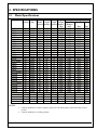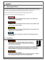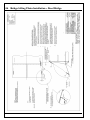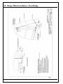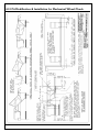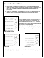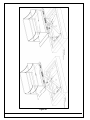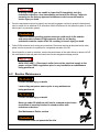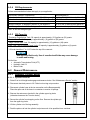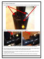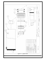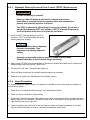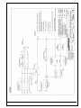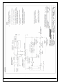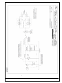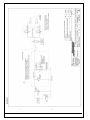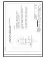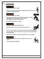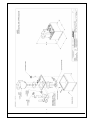
1
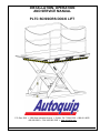
INSTALLATION, OPERATION
AND SERVICE MANUAL
PLTC SCISSORS DOCK LIFT
P.O. Box 1058 • 1058 West Industrial Avenue • Guthrie, OK 73044-1058 • 888-811-9876
405-282-5200 • FAX: 405-282-3302 • www.autoquip.com
1
Item #830PLT
Version 5.0
9/2014
1.
Introduction And Warranty ............................................................................................................ 4
1.1
Introduction .................................................................................................................................4
1.1.1
Identification ..........................................................................................................................4
1.1.2
Inspection..............................................................................................................................4
1.1.3
Planned Maintenance Program .............................................................................................4
1.2
Responsibility Of Owners/Users..................................................................................................4
1.2.1
Deflection ..............................................................................................................................4
1.2.2
Inspection & Maintenance .....................................................................................................5
1.2.3
Removal From Service ..........................................................................................................5
1.2.4
Repairs .................................................................................................................................5
1.2.5
Operators ..............................................................................................................................5
1.2.6
Before Operation ...................................................................................................................5
1.2.7
During Operation ...................................................................................................................5
1.2.8
Modifications Or Alterations...................................................................................................5
1.3
Warranty .....................................................................................................................................6
2.
Specifications ................................................................................................................................. 7
2.1
Model Specifications ...................................................................................................................7
2.2
Lift Specifications ........................................................................................................................8
2.3
Load Capacity .............................................................................................................................8
2.4
Unbalanced Loading ...................................................................................................................8
2.5
Pump Pressure ...........................................................................................................................8
2.6
Lift Duty ......................................................................................................................................8
3.
Safety .............................................................................................................................................. 9
3.1
Safety Signal Words ...................................................................................................................9
3.2
Installation...................................................................................................................................9
3.3
Operation ..................................................................................................................................10
3.4
Hydraulics .................................................................................................................................10
3.5
Maintenance .............................................................................................................................11
3.6
Modifications .............................................................................................................................11
3.7
Labels .......................................................................................................................................12
4.
Installation .................................................................................................................................... 15
4.1
Remote Power Unit Installation .................................................................................................15
4.2
Power Unit Wiring .....................................................................................................................15
4.2.1
Contractor Remote Power Unit............................................................................................15
4.2.2
Heavy Duty Remote Power Unit ..........................................................................................15
4.3
Pit Installation ...........................................................................................................................16
4.4
Surface Installation ...................................................................................................................21
4.5
Shimming And Anchoring Lift To Concrete................................................................................21
4.6
Bridge Lifting Chain Installation – Steel Bridge .......................................................................... 22
4.7
Bridge Lifting Chain Installation – Aluminum Bridge .................................................................. 23
4.8
Bridge Winch Installation – Steel Bridge ...................................................................................24
4.9
Bridge Winch Installation – Aluminum Bridge ............................................................................ 25
4.10
Pit Modification & Installation for Mechanical Wheel Chock ...................................................... 26
4.11
Accordion Skirt Installation ........................................................................................................27
5.
Operation ...................................................................................................................................... 28
5.1
Raise And Lower Lift .................................................................................................................28
5.2
Raise And Lower Bridge (hydraulic) ..........................................................................................28
6.
Maintenance ................................................................................................................................. 29
6.1
Maintenance Device .................................................................................................................29
6.2
Routine Maintenance ................................................................................................................31
6.2.1
Every Day Or 10 Hours Of Operation ..................................................................................32
6.2.2
Every Month Or 100 Hours Of Operation............................................................................. 32
6.2.3
Every Year Or 1000 Hours Of Operation ............................................................................. 32
2
6.2.4
Oil Requirements ................................................................................................................ 33
6.2.5
Oil Capacity ........................................................................................................................ 33
6.3
General Maintenance ............................................................................................................... 33
6.3.1
Hydraulic Cylinder Repair ................................................................................................... 33
6.3.2
Bleeding Air From System .................................................................................................. 36
6.3.3
Hydraulic Velocity Fuse and Flow Control (VF/FC) Replacement ........................................ 37
6.3.4
Hose Orientation ................................................................................................................. 37
6.3.5
Schematics and Field Wiring Details ................................................................................... 38
6.3.6
Troubleshooting .................................................................................................................. 50
7.
Parts Lists .................................................................................................................................... 54
3
1. INTRODUCTION AND WARRANTY
1.1 Introduction
Please read and understand this manual prior to installation or operation of this lift. Failure to do so could
lead to property damage and/or serious personal injury. If you have any questions, call a local dealer or
Autoquip Corporation at 1-888-811-9876 or 405-282-5200.
Please record the following information and refer to it when calling your dealer or Autoquip.
Model Number:________________Serial Number: ___________________
Installation Date _____/_____/_____
1.1.1
Identification
When ordering parts or requesting information or service on this lift, PLEASE REFER TO THE MODEL
AND SERIAL NUMBER. This information is on a nameplate attached to the leg assembly. Replacement
parts are available from a local Autoquip distributor.
1.1.2
Inspection
Upon receipt of lift, perform a visual inspection to determine whether the lift has been damaged in transit.
Any damage found must be noted on delivery receipt. In addition to this preliminary inspection, carefully
inspect lift for concealed damage. Any concealed damage found that was not noted on delivery receipt
must be reported in writing to the delivering carrier within 48 hours.
Use the following checklist for inspection of lift:
1. Examine entire unit for any signs of mishandling. Carefully check power unit and controls.
2. Thoroughly examine all connections, making sure they have not vibrated loose during transit, and
inspect wiring for any signs of damage.
3. After installation, raise lift and inspect base frame, platform, scissors assembly, and cylinder plumbing
connections.
1.1.3
Planned Maintenance Program
A local Autoquip representative provides a Planned Maintenance Program (PMP) for this equipment using
factory-trained personnel. Call a local representative or Autoquip Corporation at 1-888-811-9876 or 405282-5200 for more information.
1.2 Responsibility Of Owners/Users
1.2.1
Deflection
It is the responsibility of user/purchaser to advise manufacturer where deflection may be critical to the
application.
4
1.2.2
Inspection & Maintenance
Lift must be inspected and maintained in accordance with Autoquip’s operating/maintenance (O&M)
manual and with other applicable safe operating practices.
1.2.3
Removal From Service
Any lift not in safe operating condition such as, but not limited to, excessive leakage, missing parts or
fasteners, any bent or cracked structural members, cut or frayed electric, hydraulic, or pneumatic lines,
damaged or malfunctioning controls or safety devices, etc. shall be removed from service until it is
repaired to the original manufacturer’s standards.
1.2.4
Repairs
All repairs must be made by a qualified technician in conformance with Autoquip’s instructions.
1.2.5
Operators
Only trained personnel and authorized personnel shall be permitted to operate lift.
1.2.6
Before Operation
Before using lift, operator must:
• Read and/or had explained, and understood, manufacturer’s operating instructions and safety
rules.
• Inspect lift for proper operation and condition. Any suspect item must be carefully examined and a
determination made by a qualified person as to whether it constitutes a hazard. All items not in
conformance with Autoquip’s specification must be corrected before operating lift.
1.2.7
During Operation
Use lift in accordance with Autoquip’s O&M manual.
• Do not overload lift.
• Verify all safety devices are operational and in place.
• Autoquip warrants this lift for 60,000 cycles each warranty year. This number of cycles represents
normal, single shift duty. Exceeding this number of cycles shortens life of lift and length of your
warranty.
1.2.8
Modifications Or Alterations
Modifications or alterations to this equipment may be made only with written permission of Autoquip.
Unauthorized modification or alteration will void warranty.
5
1.3 Warranty
The user is solely responsible for using this equipment in a safe manner and observing all of the safety
guidelines provided in the Owner’s Manual and on the warning labels provided with the lift. If you are
unable to locate either the manual or the warning labels, please contact Autoquip or access
www.autoquip.com for replacement downloads or information.
Autoquip Corporation expressly warrants that this product will be free from defects in material and
workmanship under normal, intended use for a period of Two (2) Years for Labor and all electrical,
mechanical, and hydraulic components, parts or devices, and warrants the structure of the lift against
breakage or failure for a period of Five (5) years. The warranty period begins from the date of shipment.
When making a claim, immediately send your dealer or Autoquip notice of your claim. All claims must be
received by Autoquip within the warranty time period. The maximum liability of Autoquip, under this
Limited Warranty, is limited to the replacement of the equipment.
This warranty shall not apply to any Autoquip lift or parts of Autoquip lift that have been damaged or
broken in transit/shipping, or due directly or indirectly to misuse, abuse, vehicle impact, negligence, faulty
installation, fire, floods, acts of God, accidents, or that have been used in a manner contrary to the
manufacturer’s limitations or recommendations as stated in the manual, or that have been repaired,
altered or modified in any manner outside of Autoquip Corp’s manufacturing facility or which have not
been expressly authorized by Autoquip.
Autoquip Corporation makes no warranty or representation with respect to the compliance of any
equipment with state or local safety or product standard codes, and any failure to comply with such codes
shall not be considered a defect of material or workmanship under this warranty. Autoquip Corporation
shall not be liable for any direct or consequential damages resulting from such noncompliance.
Autoquip Corporation’s obligation under this warranty is limited to the replacement or repair of defective
components at its factory or another location at Autoquip Corp’s discretion at no cost to the owner. This is
owner’s sole remedy. Replacement parts (with exception of electrical components) will be warranted for a
period of ninety (90) days. Except as stated herein, Autoquip Corporation will not be liable for any loss,
injury, or damage to persons or property, nor for direct, indirect, or consequential damage of any kind,
resulting from failure or defective operation of said equipment. All parts used to replace defective material
must be genuine Autoquip parts in order to be covered by this Limited Warranty.
AUTOQUIP CORP
P.O. Box 1058, Guthrie, OK 73044-1058
Telephone: (888) 811-9876 ∙ (405) 282-5200
Fax: (405) 282-3302
www.autoquip.com
6
2. SPECIFICATIONS
2.1 Model Specifications
Model
Travel Capacity Platform Platform Lowered Shipping
Axle Load Capacity
(inches) (lbs)
Width Length Height Weight Clevis End Roller End Sides
(inches) (inches) (inches) Approx. (Bridge)
(lbs)
(lbs)
(lbs)
(lbs)
PLTC-6050
60
5000
72
100
8
2800
3000
3000
2500
6050A
60
5000
96
100
8
3300
3000
3000
2000
6050S
60
5000
72
120
8
3400
2000
2000
2500
6050B
60
5000
84
120
8
3400
2000
2000
2250
6050K
60
5000
96
120
8
3600
2000
2000
2000
PLTC-6060
60
6000
72
100
8
3000
3000
3000
2500
6060A
60
6000
96
100
8
3400
3000
3000
2000
6060S
60
6000
72
120
8
3400
2000
2000
2500
6060B
60
6000
84
120
8
3500
2000
2000
2250
6060K
60
6000
96
120
8
3600
2000
2000
2000
PLTC-6070
60
7000
72
96
12
4600
6400
6400
6400
6070A
60
7000
96
96
12
4780
6400
6400
5400
6070S
60
7000
72
120
12
4800
6400
6400
6400
6070B
60
7000
84
120
12
4900
6400
6400
6000
6070K
60
7000
96
120
12
5100
6400
6400
5400
PLTC-6080
60
8000
72
96
12
4700
6400
6400
6400
6080A
60
8000
96
96
12
4890
6400
6400
5400
6080S
60
8000
72
120
12
4800
6400
6400
6400
6080B
60
8000
84
120
12
5100
6400
6400
6000
6080K
60
8000
96
120
12
5300
6400
6400
5400
PLTC-60100
60
10000
72
100
12
4800
8000
8000
6400
60100A
60
10000
96
100
12
4990
8000
8000
5400
60100S
60
10000
72
120
12
4900
6400
6400
6400
60100B
60
10000
84
120
12
5200
6400
6400
6000
60100K
60
10000
96
120
12
5400
6400
6400
5400
PLTC-58120
58
12000
72
100
12.5
4900
10000
10000
8000
58120A
58
12000
96
100
12.5
5100
10000
10000
6400
58120S
58
12000
72
120
12.5
5300
8000
8000
8000
58120B
58
12000
84
120
12.5
4950
8000
8000
7200
58120K
58
12000
96
120
12.5
5500
8000
8000
6400
PLTC-58150
58
15000
72
100
12.5
4900
10000
10000
8000
58150A
58
15000
96
100
12.5
5100
10000
10000
6400
58150S
58
15000
72
120
12.5
5300
8000
8000
7200
58150B
58
15000
84
120
12.5
4950
8000
8000
8000
58150K
58
15000
96
120
12.5
5500
8000
8000
6400
NOTES:
•
•
All PLTC Models have a rollover capacity equal to twice the lifting capacity when in the fully lowered
position.
All PLTC Models have (2) lifting cylinders.
7
2.2 Lift Specifications
There are many custom designs whose specifications may vary from those published for standard models.
Please consult the specific General Arrangement (GA) Drawing to obtain the specifications for applicationspecific designs.
2.3 Load Capacity
Load capacity rating is stamped on a metal nameplate attached to lift. This figure is a net capacity rating
for a lift furnished with a standard platform. If optional items are installed on lift after leaving manufacturer,
deduct weight of these from load rating to obtain net capacity.
Do not exceed rated capacity of lift. Loading lift beyond its rated capacity is unsafe, will shorten
operational life of lift, and will void warranty.
2.4 Unbalanced Loading
The stabilization provided is basically for balanced loads. If special attachments extend beyond the length
and/or width dimensions of platform, end and/or side load capacity is reduced 2% for each one-inch
extension from edge of platform. If load is rolling onto platform (in any but fully-lowered position) end
and/or side load capacity is reduced by dividing the rated end/side load by 1.50 to establish an available
“axle” load.
2.5 Pump Pressure
This lift incorporates a unique, positive displacement pump. Therefore, standard factory models of same
manufacture cannot replace it.
Pump can operate efficiently at intermittent pressures up to 3200 PSI and continuous duty to 2500 PSI.
The factory installed safety relief valve is factory-set to stay within parameters of pump and lift
requirements.
2.6 Lift Duty
Autoquip warrants this lift for 60,000 cycles each warranty year. This number of cycles represents normal,
single shift duty. Exceeding this number of cycles shortens life of lift and length of your warranty
It is the responsibility of the user to notify Autoquip whenever a specific application is likely to demand
“above normal” duty from lift. Above normal duty typically requires supplemental design features to
enhance serviceable life of lift and to avoid loss of warranty.
8
3. SAFETY
3.1 Safety Signal Words
This Owner’s Manual covers PLTC lift models produced by Autoquip. Before installing, operating or
servicing lift, you must read, understand and follow the instructions and safety warnings in this manual.
Your lift may not be equipped with some optional equipment shown in this manual.
The safety information in this manual is denoted by the safety alert symbol: i
The level of risk is indicated by the following signal words.
i DANGER
DANGER – Indicates a hazardous situation, which, if not avoided, will
result in death or serious injury.
i WARNING
WARNING – Indicates a hazardous situation, which, if not avoided, could
result in death or serious injury.
i CAUTION
CAUTION – Indicates a hazardous situation, which, if not avoided, could
result in minor or moderate injury.
NOTICE
NOTICE – Indicates a situation that could result in damage to the lift or
other property.
3.2 Installation
i WARNING
Do not install lift in a pit unless pit has a bevel toe guard or
other approved toe protection. A shear point can exist which
can cause severe foot injury.
Lift platforms traveling below floor levels may create a toe hazard as load
passes top edge of pit. This may require guarding in accordance with
Federal Regulations. Guarding must be installed prior to operating lift.
i WARNING
Prevent serious injury or death.
Depending on model, standard weight of lift ranges from 2800 – 5500 lbs.
Use a properly rated lifting device to move and install lift.
9
3.3 Operation
i WARNING
Prevent serious injury or death.
Scissor lifts are designed for a specific load and application. Do not
change load or application from original design.
Overloading, or uneven loading, could result in load instability and cause
serious personal injury.
Stay clear of lift while lift is in motion.
Never stand, sit or ride on lift unless equipped with OSHA-compliant
personnel guarding on the platform.
i WARNING
Prevent serious injury or death.
Lifts which travel to an elevation above floor level where distance between
floor and the underside of lift platform exceeds 66" must have the
scissors mechanism guarded per ANSI MH29.1.
3.4 Hydraulics
Fluids can be hazardous. Before servicing lift, check Material Safety Data Sheet (MSDS) to understand
the product, safe handling procedures, and first aid measures relating to product. Follow this information
when servicing or repairing lift.
Do not drain or pour any fluids or lubricants into ground. Check with local environmental agencies,
recycling centers, or your Autoquip dealer for correct disposal information.
i CAUTION
Any time velocity fuses have been tripped, investigate cause of trip and
verify necessary corrective actions have been taken prior to operation of
lift.
i WARNING
Prevent serious injury or death.
Do not attempt to remove Hydraulic Velocity Fuse (HVF) until maintenance
device securely supports lift and all hydraulic pressure has been relieved.
HVF is attached to elbow fitting in pressure port of cylinder. Do not use a
swivel fitting between HVF and cylinder. If HVF is installed improperly, it
will not lock up in event of a hydraulic line failure.
10
i WARNING
Pressurized fluids can penetrate the skin.
Hydraulic hoses can fail from age, damage and exposure.
Do not search for hydraulic leaks without body and face protection. A tiny,
almost invisible leak can penetrate the skin, thereby requiring immediate
medical attention.
Use wood or cardboard to detect hydraulic leaks, never your hands.
i WARNING
Spilled fluids and lubricants may be slippery and may also
present a fire hazard.
Clean up spilled fluids and lubricants.
3.5 Maintenance
i WARNING
Prevent serious injury or death.
Disconnect and/or lock out electrical supply to power unit prior to any
maintenance being performed.
i WARNING
Prevent serious injury or death.
Never go under lift platform until load is removed and scissors
mechanism is securely blocked in raised position with
maintenance devices.
3.6 Modifications
i WARNING
Prevent serious injury or death.
Do not modify lift. Autoquip cannot foresee and is not responsible for
injury or damage which results from unauthorized modifications or
misuse of lift.
11
3.7 Labels
i WARNING
To protect against death or serious injury, all labels must be on lift and
must be legible.
If any of these labels are missing or cannot be read, call Autoquip for
replacement labels.
12
1 – 36401594
2 – 36430050M
3 – 36401487
4 – 36401560
5 – 06100010
13
6 – 36403225
7 – 36400265
8 – 36400257
9 – 36403715
14
4. INSTALLATION
4.1 Remote Power Unit Installation
1. The remote power unit is to be located in an area protected from the elements and should be installed
prior to the lift to facilitate lift operation during installation into the pit.
2. The remote contractor power unit is equipped with power unit mounting brackets and can be wall or
floor mounted using these brackets. If equipped with a vertical power unit, optional power unit
mounting brackets must be used for wall mounting.
3. The electrical work is to be done in accordance with local codes by a qualified electrician. See the
“Maintenance” section for the standard wiring diagram.
4. If permanent electrical work is not complete, some means of temporary power with an on/off device for
the motor will be required.
5. Fill the reservoir with oil per instructions in the "Maintenance” section.
4.2 Power Unit Wiring
4.2.1
Contractor Remote Power Unit
1. The Contractor Power Unit utilizes a 5 HP / 208-230-460 Volt / 60 hertz / 3 phase “Super-Torque”
intermittent duty motor with (one full lift cycle per 2 minute period) driving a high pressure positive
displacement pump assembly with an internal relief valve, check valve and down solenoid valve.
2. Because an Autoquip "Super-Torque" motor actually delivers substantially more horsepower than the
nameplate rating, it must always be wired for heavier current-draw than standard motors of the same
nameplate rating. However, because of the "Super-Torque" motor’s starting efficiency and superior
running characteristics, circuit components do not have to be as large as for standard motors of equal
delivered horsepower.
3.
4.2.2
Heavy Duty Remote Power Unit
1. The Vertical 'HD' Power unit utilizes a 5 HP/ 208-230-460 Volt / 60 hertz / 3 phase Heavy Duty motor,
(with a 30 minute continuous duty rating). The power unit is coupled with a high-pressure positive
displacement gear pump, and Autoquip Corporation’s patented Deltatrol valve assembly.
2. The motor connection diagram should be referenced in connecting the motors to a power source.
Remember that heavy wire must be used all the way to the power source.
3.
NOTE: For larger horsepower motors, consult factory.
HP
3
5
5 (Contractor )
5 (Vertical HD)
5 (Continuous)
Motor Details
HZ
PH
RPM
60
1
1725
60
1
1800
60
3
3450
60
3
3475
60
3
1760
Time Rating
2 Min.
2 Min.
2 Min.
2 Min.
Continuous
15
115V
33.6
-
Full Load Amps
208V
230V
16.8
16.8
25.2
23.0
15.8
14.8
16.0
15.2
13.6
12.6
460V
7.4
7.6
6.6
i WARNING
Prevent serious injury or death.
Electrical service installation must be performed by a licensed
electrician and conform to all local and national electrical codes.
4.3 Pit Installation
i WARNING
Do not install lift in a pit unless lift has a bevel toe guard or
other approved toe protection. A shear point may exist which
can cause severe foot injury.
Lift platforms traveling below floor levels may create a toe hazard as load
passes top edge of pit. This may require guarding in accordance with
ANSI MH29.1. Guarding must be installed prior to operating lift.
1. Check pit dimensions (Reference drawing 82600431 below). Pit should be 2" longer and 2” wider than
lift platform to allow a 1” gap between platform and pit. Pit depth should allow ½” for shims or grout.
2. Conduit diameter must be a minimum of 3" with long radius sweeps for necessary hydraulic hosing
and field wiring.
3. Verify installation area is clean before starting. Check mounting surface of pit floor with a level or
straight edge. If floor is not level, add shims or grout under entire perimeter of base to achieve a level
and flat base installation. A level base is essential for proper wheel tracking and smooth lift operation.
i WARNING
Prevent serious injury or death.
Depending on model, standard weight of lift ranges from 500 – 4700 lbs.
Use a properly rated lifting device to move and install lift.
16
PLT Pit Detail
See Pit Installation Notes
17
4. Make temporary hose connections with high-pressure hose (see chart below) to allow the lift to be
operated when it is set in the pit.
5. Temporarily connect electrical service and hydraulic hoses. The hose connection on the end of the
base frame is 1/2" female NPT.
Hydraulic Piping/Hose Size
Up to 25 feet
½” ID
26 feet to 50 feet
¾” ID
Over 50 feet
1” ID
6. Fittings have been provided to extend the hose connection outside the bevel toe guard. Point the
elbow toward the pipe chase in the pit.
7. Check the routing of the temporary hydraulic lines to assure that the hose is clear of legs, base frame,
and platform when lift is in the lowered position.
8. Using 3/4-10 UNC eyebolts and a chain spreader, place the lift into the pit as illustrated below.
18
Lifting and Installation
19
9. Check for proper height. Lift must be solid and flush with pit curb angle framing (D). If needed, shim to
desired height. DO NOT “spot” shim. Shim along full length of frame. This will prevent frame from
sagging under load.
10. Remove the shipping bolt and eye bolts from the lift and hydraulically raise the platform.
i CAUTION
Failing to remove the shipping bolts before operation will cause
permanent damage to the lift.
11. Fill hydraulic reservoir with proper type and volume of fluid.
12. Press “UP button and raise lift one foot.
13. Press “DOWN” button to fully lower lift. Continue to hold down button for
60 seconds. Repeat procedure five to seven times to bleed air out of
hydraulic system.
14. Raise and lower lift as needed to make positioning adjustments.
15. Adjust platform to a clearance of 1” minimum around perimeter between
platform and pit angle.
i WARNING
NEVER go under a raised lift platform until load is removed and
lift is securely blocked in raised position with maintenance
devices.
See "Maintenance Device" section of this manual.
Lock-out/tag-out power source.
16. Base frame of lift has pre-drilled holes for anchoring to the floor. Anchor lift to floor. Lifts with oversize
platforms have minimum pull out requirements of 2,000 lbs. for each anchor. See “Shimming And
Anchoring Lift To Concrete”.
17.
18. Make permanent electrical and hydraulic connections and operate lift through a few cycles.
19. Clean up debris and spilled oil from area. Dispose of oil in an environmentally safe manner.
20. Touch-up paint is available from Autoquip for repair of damaged paint surfaces.
21. Train personnel on lift operation, all safety features and procedures.
20
4.4 Surface Installation
Surface installation procedures are the same as for pit installation instructions with the following
consideration:
NOTICE
The surface area where the lift will be set must be flat and level and be of
sound concrete of sufficient thickness to support the lift while loaded at
full capacity. Asphalt is not sufficient support for the lift.
22.
4.5 Shimming And Anchoring Lift To Concrete
Recommended concrete anchor bolts are: HILTI “Kwik-Bolt”, Molly Parabolt or similar.
1. Verify lift is positioned correctly.
2. Raise the platform and install the maintenance leg (see
“Maintenance Device Instructions” section).
3. Drill holes in concrete as specified by anchor bolt
manufacturer.
4. Install and tighten anchors as specified by anchor bolt
manufacturer.
5. Each lag bolts should be able to withstand 2000lbs.
minimum upward pull.
6. After lift has been aligned, leveled and shimmed, and
anchors have been installed, pour grout under entire
base frame.
7. When grout has set and cured, tighten nuts on anchor bolts.
8. Route hydraulic hose or electrical cord through conduit in pit wall.
21
4.6 Bridge Lifting Chain Installation – Steel Bridge
22
4.7 Bridge Lifting Chain Installation – Aluminum Bridge
23
4.8 Bridge Winch Installation – Steel Bridge
24
4.9 Bridge Winch Installation – Aluminum Bridge
25
4.10 Pit Modification & Installation for Mechanical Wheel Chock
26
4.11 Accordion Skirt Installation
1. Position platform in raised position. Engage maintenance device (see “Maintenance Device”
section). Remove the handrails. Position accordion with weight rod pocket at bottom and mounting
collar at top. The breathable material when provided must be positioned at top of skirt with
mounting collar.
2. Slip skirt over end of platform. Turn skirt as required to slide over other end of platform and leg
assembly. The skirt should be in position under platform while enveloping base assembly.
3. Select from the following mounting configurations.
Raise one side of skirt along with a skirt-mounting bar (1/8” x
1”) to side of bevel toe guard. When possible, center skirtmounting collar and skirt-mounting bar (1/8” x1”) on platform.
Align pre-drilled holes in platform with skirt-mounting bar holes
and punch holes in skirt-mounting collar.
Push a nylon drive rivet through each hole in skirt-mounting bar.
Hammer aluminum pin into rivet until flush with rivet head.
Repeat mounting process for remaining sides of accordion skirt.
Bevel Toe Guard (Typical)
Platform Side
Under Platform
4. Install weight rods into weight rod pockets at bottom of accordion skirt. Install spring tempered wire
rods into pocket of black convolutions.
27
5. OPERATION
5.1 Raise And Lower Lift
i WARNING
Prevent serious injury or death.
Before operating lift, all personnel interacting with lift must read, understand
and follow instructions and safety warnings in this manual.
Personnel must maintain a safe operating distance of at least 36” any time
lift is operated.
NOTICE
Adjusting safety relief valve may result in premature motor failure.
Do not adjust safety relief valve.
Raising loads exceeding rated capacity of lift may result in excessive wear and
damage to lift.
For lifts supplied with throw-over bridges, make sure bridges are in the stored
(raised) position prior to raising or lowering the lift, and when backing up trucks
for loading/unloading - to ensure that the bridges will clear all possible
obstructions and contact with a moving truck.
1. Verify all personnel are clear of lift.
2. Press “UP” button to raise lift. Release button when lift reaches desired
position.
NOTICE
Do not operate lift on relief for more than a few seconds.
When on relief, valve will make a squealing sound.
3. Press "DOWN" button to lower lift. Release button when lift reaches
desired position.
5.2 Raise And Lower Bridge (hydraulic)
If your lift has a hydraulically operated throw over bridge (TOB), it is equipped with UP/DOWN buttons and
a FLOAT switch. The FLOAT switch must be set to “LOCK” for the UP/DOWN buttons to work. The
UP/DOWN operate just as the lift UP/DOWN. The FLOAT switch is to be used when the bridge is resting
on the truck bed. The “FLOAT” mode allows the bridge to float up or down with the truck.
This prevents damage to the equipment when loads are being moved across the bridge.
Note: Bridges that hang below 45 degrees are in violation of ANSI Standard MH29.1-2012 paragraph
4.12.2 which states “When a hinged bridge is in its fully lowered position and not resting on a truck bed or
landing, it should hang down at an angle not to exceed approximately 45 degrees from horizontal.…”
Autoquip’s standard is to allow 20° of drop below horizontal.
28
6. MAINTENANCE
6.1 Maintenance Device
i WARNING
NEVER go under a raised lift platform until load is removed
and lift is securely blocked in raised position with maintenance
device.
Lock-out/tag-out power source.
This procedure describes the only factory-approved method of working under a lift. Follow these
instructions EVERY time you plan to reach or crawl beneath the lift to perform service or maintenance –
no matter how momentary that might be.
If the factory-provided maintenance device is damaged or missing, stop immediately and consult the
factory for assistance. The manufacturer is not liable for your failure to use the approved maintenance
device and procedures that have been provided.
1. All loads must be removed from the lift prior to engaging the maintenance device. These devices are
designed to support an unloaded lift only. Failure to remove the load from the lift prior to blocking could
cause the failure of the maintenance device and allow the lift to fall unexpectedly. This can result in
personal injury or death.
2. Raise the lift to its fully raised position. If you do not, the maintenance device may not be able to be
placed properly in its designed blocking position.
3. The lift will be provided with one (1) maintenance device stored at the clevis end of the lift (either under
the platform or between the legs). The device must be securely placed inside the leg socket on the
base frame. (See Figure 6.1).
4. Lower the lift platform until it comes down and makes contact with the maintenance leg. The
maintenance leg should be centered in maintenance leg collar located underneath the platform on the
clevis end. Re-check to ensure that the maintenance leg device is inside the maintenance collar and in
contact with the platform deck surface. If the maintenance leg is not fully engaged the lift could fall
unexpectedly, resulting in permanent damage to the device or the lift.
29
Figure 6.1
30
i DANGER
If for any reason you are unable to lower the lift completely onto the
maintenance devices, stop immediately and consult the factory. Failure to
properly use the factory approved maintenance devices could result in
severe injury or death.
5. Once the maintenance device is properly and securely engaged, continue to press the down button,
valve or switch for an additional 5-10 seconds to relieve all pressure in the hydraulic system (it could
take longer in a pneumatic system).
i WARNING
Failure to relieve operating system pressure could result in the sudden
and unexpected release of high-pressure fluids (or air) during
maintenance and/or repair of the lift, resulting in severe injury or death.
6. Follow OSHA electrical lock-out/tag-out procedures. Disconnect and tag all electrical and/or other
power sources to prevent an unplanned or unexpected actuation of the lift.
7. Once inspection or work is complete, reverse the performance of the steps above to raise the lift off
the maintenance locks and place the locks back into the designated storage position.
i DANGER
HIGH VOLTAGE!! – Disconnect and/or lock out the electrical supply to the
power unit per OSHA regulations prior to any installation or maintenance
being performed.
6.2 Routine Maintenance
i WARNING
Prevent serious injury or death.
Lock-out/tag-out power source prior to any maintenance
being performed.
i WARNING
Prevent serious injury or death.
Never go under lift platform until load is removed and scissors
mechanism is securely blocked in raised position with
maintenance devices.
See Maintenance Device section.
i WARNING
Pressurized fluids can penetrate the skin.
31
Hydraulic hoses can fail from age, damage and exposure.
Do not search for hydraulic leaks without body and face protection. A tiny,
almost invisible leak can penetrate the skin, requiring immediate medical
attention.
Use wood or cardboard to detect hydraulic leaks, never your hands.
i WARNING
Spilled hydraulic fluid is slippery and may also present a fire
hazard.
Clean up spilled hydraulic fluid.
Normally, scissor lifts will require very little maintenance. However, a routine maintenance program could
prevent costly replacement of parts and/or downtime.
6.2.1 Every Day Or 10 Hours Of Operation
•
•
•
•
•
•
•
Check reservoir fluid level.
Check for fluid leaks.
Check all hoses and electrical cords for cracks, abrasions, twisting, etc. Small leaks at connections
can be remedied by tightening connections or replacing faulty component.
Check that oil pressure does not exceed 3,000 psi.
Check all pivot joints & roller bearings for noise and wear.
Check overall condition of unit (i.e. bends, breaks, loose or missing screws, etc.).
6.2.2 Every Month Or 100 Hours Of Operation
•
•
•
•
•
Check quality of oil. Replace if discolored (oxidized), cloudy, or otherwise contaminated. Do not
overfill reservoir. Always use clean fluid.
Inspect lift cylinder rods for scoring and leaking, wipe away any foreign material.
Inspect all structural and mechanical components for cracked or broken welds and any distortion
caused by collision, overloading, or other misuse.
Inspect snap rings/bolts at rollers & pivot points for proper retention & tightness.
Inspect cylinder trunion pin for proper retention.
When all checks have been completed, start unit and operate through all functions. Inspect all
components for signs of noise, vibration, erratic movement, and any other abnormal behavior.
6.2.3 Every Year Or 1000 Hours Of Operation
•
•
•
•
•
Change oil and clean reservoir. Always use clean fluid. Never return fluid from drip pans, pit, etc.
back to reservoir. Dispose of and handle used fluid as a hazardous material.
If noise or vibration has been noticed, remove lift cylinder pins, pivot pins, and roller bearings.
Inspect for wear and replace as necessary.
Inspect all hydraulic hoses. Replace any that show signs of wear or leaking.
Replace all filters.
Check for permanent mechanical deformation.
32
6.2.4
Oil Requirements
Follow recommendations below that apply to your application.
Environment (Ambient Temperature)
Indoor locations with variable temperatures: 30 - 100 degrees F.
Indoor locations with constant temperatures: 60 - 80 degrees F.
Outdoor locations: 30 - 120 degrees F.
Outdoor locations: 10 degrees F below 0 to 100 degrees F.
Cold Storage Warehouse: 10 - 40 degrees F.
Recommended Oil
5W 30 or 5W 40 Multiviscosity Motor Oil
SAE 20 Motor Oil
5W 30 or 5W 40 Multiviscosity Motor Oil
5W 20 or 5W 30 Multiviscosity Motor Oil
Contact local Autoquip Service Rep.
Note: All oils are detergent type.
6.2.5
Oil Capacity
*Contractor Polyethylene Tank: Oil capacity is approximately: (5.5) gallons or (22) quarts.
*Vertical Steel Tank: Oil capacity is approximately: (10) gallons or (40) quarts.
*Large Vertical Steel Tank: Oil capacity is approximately: (12) gallons or (48) quarts.
Steel Tube Tank for Internal Power Units: Oil capacity is approximately (2) gallons or (8) quarts.
* Oil level should be 1" to 1-1/2" below the top of the reservoir.
NOTICE
Use approved fluids only. Use of unauthorized fluids may cause damage
to seals and hosing.
Do Not Use:
• Automatic Transmission Fluid (ATF)
• Hydraulic Jack Oil
• Brake Fluids
6.3 General Maintenance
6.3.1
Hydraulic Cylinder Repair
6.3.1.1. Cylinder Removal
1. Raise lift to its full height and engage maintenance device. See “Maintenance Device” section.
2. Disconnect electrical power to lift. Follow lock out-tag out procedure.
3. Disconnect cylinder hose at the tee connection on the Base assembly.
Place the open end of the hose in a container to receive oil spillage.
4. Remove the setscrew or hex bolt in the cylinder upper leg clevis
(otherwise known as the Trunnion clevis).
5. Secure the cylinder from dropping on the floor. Remove the cylinder pin
from the upper leg clevis.
6. Lift the cylinder out of the leg assembly.
7. Push the piston rod into the cylinder to eject as much oil as possible into a container.
33
6.3.1.2. Replace Cylinder Seals
1. Insert spanner wrench and turn upper bearing assembly clockwise until tip of retainer appears in slot.
2. Place a small screwdriver under retainer and turn retainer to remove.
3. Be sure hose port is open to allow air into cylinder. Pull piston rod out to remove upper bearing.
4. After all internal components have been removed, inspect inner walls of barrel. Use a cylinder hone to
remove any apparent nicks or scratches. Clean and flush barrel after honing.
5. Remove piston head nut from rod. Upper clevis and pin may be used to prevent rotation of rod while
loosening. Remove old piston.
6. Inspect groove for nicks or scratches that could affect seal or barrel walls; remove as necessary.
34
Figure 6.3 – Cylinder Seals
35
7. Install new piston, seals, and rod wiper.
8. Install and tighten piston head nut to 325 ft•lb of torque. Upper clevis and pin may be used to prevent
rotation of rod while tightening.
9. Liberally lubricate piston and seal with clean grease or oil.
10. Insert piston into barrel, taking care not to damage seal.
11. Slip bearing assembly into place and align retainer hole with slot in barrel.
12. Turn bearing with spanner wrench until retainer is reinserted completely.
6.3.1.3. Placing Cylinder Back Into Service
Loctite PST #567 pipe thread sealant or equivalent is recommended.
NOTICE
Do not use Teflon tape on hydraulic threaded connections. Tape
fragments may damage hydraulic system.
Autoquip recommends replacing any NPT fittings that have been disassembled due to their inherent
design for sealing.
1. Check that lift anchors are tight (when used). Check all pins and other mechanical and hydraulic
connections.
2. Restore oil level. See oil recommendations in “Oil Requirements” section.
3. Turn on electrical power and press “UP” button. Loosen bleeder plug at the top end of ram casing and
operate pump to remove trapped air from ram. When clear oil appears, tighten plug and raise lift
slightly to disengage maintenance locks.
4. Lower lift completely and hold “DOWN” button for 60 seconds to allow air in cylinders to bleed back
into reservoir.
5. See “Bleeding Air From System” section
6.3.2
Bleeding Air From System
1. Bleed air from system by raising lift 25-50% of full travel, then lower
completely.
2. Hold “DOWN” button for 60 seconds.
3. Repeat procedure 8-10 times. If this does not bleed all air from system,
contact Autoquip.
4. Clean up any spilled oil. Dispose of spilled oil in an environmentally safe
manner.
36
6.3.3
Hydraulic Velocity Fuse and Flow Control (VF/FC) Replacement
i WARNING
Prevent serious injury or death.
Never go under lift platform until load is removed and scissors
mechanism is securely blocked in raised position with maintenance
devices and hydraulic pressure is relieved.
The VF/FC is attached to elbow fitting in rod port of cylinder. Do not use a
swivel fitting between VF/FC and cylinder. If VF/FC is installed improperly,
it will not protect in the event of a hydraulic line failure.
1. Arrow on VF/FC indicates direction of oil flow
restriction. VF/FC must be installed with arrow
pointing away from cylinder.
NOTICE
Do not use Teflon tape on hydraulic
threaded connections. Tape
fragments may damage hydraulic
system.
Autoquip recommends replacing any NPT fittings that have been
disassembled due to their inherent design for sealing.
2. Apply Loctite PST #567 pipe thread sealant or equivalent to threads and install fuse to cylinder with
arrow pointing away from cylinder. Tighten fuse.
3. Fill reservoir to full mark if necessary with proper oil.
4. Check all fitting connections for hydraulic leaks and tighten as necessary.
5. Bleed air from system. See “Bleeding Air From System” section.
6.3.4
Hose Orientation
To prevent damage to cylinder hoses, it is necessary to establish a correct hose shape and pattern of
movement as follows:
1. Raise lift to its full height and block securely. See “Maintenance Device”.
2. Install one end of new hose to cylinder fitting.
3. Since hose is fixed at both ends, it is possible to put a twist in hose that will allow it to follow the same
pattern each time lift is operated. This twist will allow hose to travel about half way between cylinder on
right side and inner leg on right side.
4. Lower lift carefully and verify hose is free and clear of cylinder and inner leg assembly. If not, twist
hose in direction necessary to clear any obstruction and tighten swivel fitting.
37
6.3.5
Schematics and Field Wiring Details
Electric Schematic; 5HP/ 3Ph Contractor or Vertical Power Unit
38
Electric Schematic; 5HP/ 3Ph Continuous Running Vertical Power Unit
39
Electric Schematic; 5HP/ 1Ph/230V Vertical Power Unit
40
Electric Schematic; 3HP/ 1Ph/115V Vertical Power Unit
41
Hydraulic Schematic – Contractor Power Unit
42
Hydraulic Schematic – Vertical Power Unit
43
Hydraulic Schematic – Continuous Running Vertical Power Unit
44
Push Button Wiring Diagram
45
Guarded Foot Switch Wiring Diagram
46
Guarded Foot Switch Assembly
47
Optional Limit Switch Mounting Diagram – PLTC-6050 to 6060
48
Optional Limit Switch Mounting Diagram – PLTC-6070 to 58150
49
6.3.6
Troubleshooting
i WARNING
Prevent serious injury or death.
Disconnect and/or lock out electrical supply to power unit prior to any
maintenance being performed.
i WARNING
Prevent serious injury or death.
Never go under lift platform until load is removed and scissors
mechanism is securely blocked in open position.
Follow OSHA lock-out/tag-out procedure.
See "Maintenance Devices" section.
i WARNING
Pressurized fluids can penetrate the skin.
Hydraulic hoses can fail from age, damage and exposure.
Do not search for hydraulic leaks without body and face protection. A tiny,
almost invisible leak can penetrate the skin, thereby requiring immediate
medical attention.
Use wood or cardboard to detect hydraulic leaks, never your hands.
i WARNING
Spilled hydraulic fluid is slippery and may also present a fire
hazard.
Clean up spilled hydraulic fluid.
50
PROBLEM
Lift Does Not
Raise.
POSSIBLE CAUSE AND SOLUTION
Motor rotation for a 3-phase motor may be reversed. Reverse two motor electrical
leads.
Check for line or hose leak.
Check for low oil in reservoir. Add specified oil as necessary.
Load may exceed rating. See the Specifications section. Remove excess load.
Suction screen may be clogged, starving pump. Remove and clean screen. Drain
and replace oil.
Suction line may be leaking air due to a loose fitting. Tighten as needed.
Breather holes in reservoir fill plug may be clogged. Remove and clean.
Voltage may be too low to run pump with existing load. Check by measuring
voltage at motor terminals, or as near as possible, while pump is running under
load. Inadequate or incorrect wiring can starve motor when source voltage is
ample. Correct as necessary.
Down valve may be energized by faulty wiring or stuck open. Remove solenoid
and check.
Motor may be single phasing. Check wiring, fuses, etc.
Pump may be seized if motor is humming or blowing fuses on overload protection
devices. Remove pump. Pump can be rotated by hand unless seized. Check for
cracks in housing.
Lift Raises, Then
Lowers Slowly.
Down solenoid valve stem may be bent, causing valve to stick open. Replace
down solenoid valve.
Down solenoid may not be seating. Remove solenoid coil and check. If lift does
not hold with solenoid coil removed, remove and clean down valve cartridge or
replaced as necessary.
Oil line, hose, or fitting may be leaking. Check and repair if necessary.
Lift Lowers Slowly.
Check valve in pump assembly may not be seating. This is indicated by pump
shaft and motor turning backward on their own with no power applied. Generally,
this condition can be heard. Replace pump assembly.
Down solenoid is not operating properly due to debris or damage.
Check for pinched tubing or hose. Where pipe is used, check for obstruction in
line.
Thick oil due to low ambient temperatures. Add or replace with lower weight oil
that stays thin in cold conditions (5W-15, etc.)
If foam is visible in tank oil, check for loose connection in suction line between
pump and tank. Tighten connections.
51
PROBLEM
Lift Does Not Raise,
Continued.
POSSIBLE CAUSE AND SOLUTION
PROBLEM
Lift Won’t Lower.
POSSIBLE CAUSE AND SOLUTION
Solenoid coil may be incorrectly wired, burned out, not rated for the
voltage, or line voltage may be excessively low. Check voltage near
coil.
Velocity fuse may be locked. Do not attempt to remove the velocity
fuse. The following steps should be followed:
1. Remove load from lift. Inspect all fittings, hoses, and other hydraulic
components for leaks or damage.
2. If no leak or damage is noticed, attempt to pressurize lifting cylinder
by pressing “UP” button on controller for a few seconds. Immediately
release “UP” button and press “DOWN” button. If lift starts to lower,
continue pressing “DOWN” button until lift is fully lowered.
3. If lift does not lower after trying Step 2, wait approximately 10 – 15
minutes for pressure in hydraulic system to equalize. Then, press
“DOWN” button until lift is fully lowered.
4. Once lift is fully lowered, hold “DOWN” button for approximately 60
seconds to bleed air from system. This step may need to be repeated
several times to fully remove air in system by raising the lift to 50% of
its travel and lowering.
If above steps do not correct problem, contact Autoquip to obtain
instruction for further action.
52
PROBLEM
Lift Seems Bouncy During
Operation.
Motor Labors Or Heats
Excessively.
POSSIBLE CAUSE AND SOLUTION
Lower lift to closed position and continue to hold “DOWN” button an
additional 10-30 seconds to bleed air from cylinder. Do not confuse
spongy or jerky operation with small surges that may occur when
operating on rough or uneven floors.
Check for oil starvation.
Voltage may be low. Check voltage at motor terminals while pump is
running under load, not at line source or while pump is idling. Inadequate
wiring can starve motor even when source voltage is ample.
Most of Autoquip’s standard motors are rated for intermittent duty. If a
single-phase motor is being run more than 15 – 20 motor starts per hour,
or a 3-phase motor more than 200 starts per hour, the problem may be
motor over-heating.
Running against relief pressure unnecessarily due to over loaded lift or
hitting physical stops.
Failure to observe wiring diagram on nameplate for proper voltage
connections.
Pump may be binding from oil starvation, which develops high internal
heat. Check for low oil level or clogged breather holes in reservoir fill plug.
Pump can be damaged by oil starvation.
53
7. PARTS LISTS
54
Continuous Running Vertical Power Unit
55