1
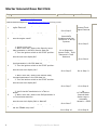
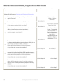
of "wake up". The time from being put to sleep until the first "wake up" sequence will also be displayed. If a combination
of three or four modules has come active, putting all of the modules back to sleep and pulling the fuse to one module at a
time will help to narrow down which module may be waking up inadvertently. Remember that module "wake up" can be
caused by several factors. They include, but are not limited to:
• input changing states - door switch going open and closed (hi/lo)
• power or ground coming and going to module
• module internal function incorrect
• Or in the case of the power master, amperage draws in excess of low power requirements or another module which has these
or other related concerns. These all can be checked with the Fluke set to 1 millisecond record speed on min/max setting.
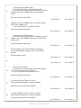
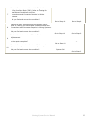
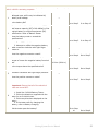
8. Open the gate on J38758, and let vehicle sit for another ten (10) minutes and/or use sleep mode.
9. Review the amperage reading.
10. As the amperage draw tapers down below 10 amps, close the J38758 and switch Fluke 87 to milliamp scale and record min/max
on 100-millisecond scale. Open the J38758 again when done. This step will allow the Fluke meter to record any spikes and keep
the meter working during the entire sequence. IF MIN/MAX IS NOT SELECTED, THE METER WILL TIME OUT AND
SHUT OFF.
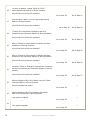
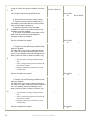
11. After the vehicle has been tested for a minimum of 8 hours, check the number of counts as per message monitor for each
control module, i.e. each time a unit goes from inactive, to active and inactive again. The module(s) with the highest number of
counts may indicate a suspect area. Modules may be waking up on their own, (which is most unlikely) or activated by a switch
input, power fluctuation, poor ground or input from other modules which are being activated.
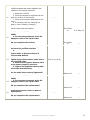
12. Once it has been determined that the draw is either a component - relay, switch etc., which is stuck or in some way
reduces/contributes to the draw, determine which circuits are specifically involved. Touching and/or removing fuses, relays, and
connectors to suspect components after reviewing the current wiring diagram until the draw is reduced to acceptable levels will
lead to the correct circuit. When exiting the message monitor screen and then re-entering the message monitor screen, the Tech
2 will also wake up modules. DON'T BE FOOLED. Wait for the module(s) to again go to sleep or use the sleep mode function.
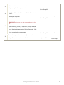
13. Back-to-basics:
• Checking ground credibility requires a voltage drop test under load
• ALWAYS TEST FROM THE NEGATIVE SIDE OF THE CIRCUIT - A voltage drop test is performed at various points
along the circuit from the ground side toward the positive side of the circuit until the point of high resistance is located.
• ALWAYS MAKE CERTAIN THAT THE CIRCUIT LOAD IS "ON"
• ALWAYS USE A HIGH IMPEDANCE METER LIKE A FLUKE 87
• THE HIGHER THE VOLTAGE READING, THE HIGHER THE RESISTANCE IN THAT CIRCUIT
• WHEN TESTING, TRY TO ACHIEVE A READING AS CLOSE TO ZERO AS POSSIBLE (USUALLY LESS THAN 25
MILLIVOLTS)
• ALWAYS START WITH A FULLY CHARGED BATTERY!
Please follow this diagnostic or repair process thoroughly and complete each step. If the condition
exhibited is resolved without completing every step, the remaining steps do not need to be performed.
GM bulletins are intended for use by professional technicians, NOT a "do-it-yourselfer". They are written to inform these technicians
of conditions that may occur on some vehicles, or to provide information that could assist in the proper service of a vehicle.
Properly trained technicians have the equipment, tools, safety instructions, and know-how to do a job properly and safely. If a
condition is described, DO NOT assume that the bulletin applies to your vehicle, or that your vehicle will have that condition. See
your GM dealer for information on whether your vehicle may benefit from the information.
36
Starting System-Service Manual
WE SUPPORT
VOLUNTARY
TECHNICIAN
CERTIFICATION