1
Outline
Section 1 - MerCruiser PDI and Maintenance - Level 1
A
B
C
D
E
F
G
-
Use of Service Literature
Engine Installation and Alignment
Stern Drive Installation
Power Steering Installation
Throttle Cable Adjustment
Pre-delivery Preparation
Winterization and Recommissioning
Section 2 - MerCruiser Electrical Systems - Level 1
A
B
C
D
E
F
G
-
Batteries / Wiring
Starting System
Charging System
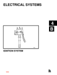
Ignition Systems
Ignition Secondary
Power Trim Electrical
Quicksilver DMT 2000 Digital
Tachometer/Multimeter Information
Section 3 - MerCruiser Fuel Systems - Level 1
A - Fuel Delivery System and Carburetion
B - Electronic Fuel Injection - Introduction
Section 4 - Service Information
MerCrusier Applicable Service Bulletin List
MerCruiser Systems (0804)
90-883145-4 (0804)
MERCRUISER
PDI AND MAINTENANCE
– LEVEL I
USE OF SERVICE LITERATURE
1
A
Table of Contents
Page
1A-1
1A-4
1A-6
Product Identification . . . . . . . . . . . . . . . . . . .
Dealer Service Publications . . . . . . . . . . . . .
Product Line Familiarization . . . . . . . . . . . . .
MerCruiser Power Package
Components . . . . . . . . . . . . . . . . . . . . . . . . . 1A-7
496 Magnum (8.1 Similar) . . . . . . . . . . . 1A-7
V-6 Shown (Small Block
V-8 Similiar) . . . . . . . . . . . . . . . . . . . . . 1A-7
Exhaust Systems . . . . . . . . . . . . . . . . . . . . . . 1A-8
Cooling System . . . . . . . . . . . . . . . . . . . . . . . . 1A-10
Transom Assembly . . . . . . . . . . . . . . . . . . . . . 1A-11
MerCruiser Drives (Typical) . . . . . . . . . . . . . . 1A-12
1A-i - USE OF SERVICE LITERATURE
90-883145-3 (10/03)
Product Identification
MerCruiser Sterndrive - Gas Typical Serial Number Locations
10-28642*
1– Engine Serial Number & Specifications
2– Engine Serial Number
* – P/N for Attaching Screw
3– Transom Serial Number
4– Drive Serial Number
5– Propeller Part Number
6– Propeller Pitch
7– Vessel Serial Number
90-883145-3 (10/03)
USE OF SERVICE LITERATURE - 1A-1
MerCruiser Inboard Typical Serial Number Locations
The serial numbers are the manufacturer’s keys to numerous engineering details which apply to your
MerCruiser power package. When contacting your Authorized MerCruiser Dealer about service, always
specify model and serial numbers.
10-28642
1– Engine Serial Number & Specifications
2– Engine Serial Number
3– Transmission Serial & Model Numbers
4– Vessel Serial Number
1A-2 - USE OF SERVICE LITERATURE
90-883145-3 (10/03)
MerCruiser Sterndrive - Diesel Typical Serial Number Locations
The serial numbers are the manufacturer’s keys to numerous engineering details which apply to your MerCruiser power package. When contacting your Authorized MerCruiser Dealer about service, always specify
model and serial numbers.
1A– Model & Serial Number Plate
1B– Serial Number Plate
2 – Transom Serial Number
3 – Drive Serial Number
4 – Propeller Part Number
5 – Propeller Pitch
6 – Vessel Serial Number
7 – Exhaust Gas Emissions Certificate Number
90-883145-3 (10/03)
USE OF SERVICE LITERATURE - 1A-3
Dealer Service Publications
Dealer Publications and Starting Serial Number Guide (830571)
Mercury Precision Parts and Quicksilver Accessories Guide
(dealer version – 42000-XX {US}, 814817-XX {Canada}; consumer version – 18379-XX {US})
MerCruiser Special Tools Catalog (806737003)
Installation Instruction Sheets
1A-4 - USE OF SERVICE LITERATURE
90-883145-3 (10/03)
Dealer Operations Guide (827690-XX)
Dealer Propeller Guide (859429-XX)
Service Manuals
Service Bulletins
Parts Bulletins
90-883145-3 (10/03)
USE OF SERVICE LITERATURE - 1A-5
Product Line Familiarization
Sterndrives
Ski
Inboard
1A-6 - USE OF SERVICE LITERATURE
90-883145-3 (10/03)
MerCruiser Power Package Components
Engines
496 MAGNUM (8.1 SIMILAR)
77635
V-6 SHOWN (SMALL BLOCK V-8 SIMILIAR)
77812
90-883145-3 (10/03)
USE OF SERVICE LITERATURE - 1A-7
Exhaust Systems
Typical Sterndrive Exhaust Components
c
a
b
a
b
c
d
e
f
a
- Clamps
- Exhaust Pipe Elbow
- Exhaust Hose
- Water Shutters
- Bolts And Lockwashers
- Exhaust Pipe
a
a
d
c
e
i
72737
f
h
d
k
e
k
h
g
a
e
b
d
j
j
f
c
c
b
b
70593
g
f
k
a
70621
j
78792
i
i
Elbows With Risers
b
75749
Elbows Without Risers
a
b
c
d
e
f
g
- Exhaust Elbow
- 4 Slot Gasket
- 3 in. (76 mm) Exhaust Riser
- 6 in. (152 mm) Exhaust Riser
- Nut (8)
- Stud (8) 9-3/8 in. (238 mm)
- Stud (8) 10-3/8 in. (264 mm) Used With
Some MIE Remote Oil Filters
h - Washer (8)
i - Exhaust Manifold
j - Bolts
1A-8 - USE OF SERVICE LITERATURE
Dry-Joint Exhaust System – V6 and Small
Block V8 (S/N MIE 0M317000 and Up – MCM
0M600000 and Up)
a - Exhaust manifold
b - Manifold-to-cylinder head bolt (4)
c - Restrictor gasket, with turbulator (seawater
cooled models)
d - 76 mm (3 in.) cold riser
e - 152 mm (6 in.) cold riser
f - Riser to exhaust manifold screw (4)
g - Full flow gasket, with turbulator
h - Exhaust elbow
i - Exhaust elbow to riser or exhaust manifold
screw and washer (4 each)
j - Hose fitting
k - Pipe plug
90-883145-3 (10/03)
Typical Inboard Exhaust System Components
a - Water Line
b - Minimum Exhaust Elbow Height with Maximum
Load 15 in. (381 mm) on 8.1S Models; 13 in. (330
mm) on All Others
c - 4 in. (102 mm) I.D. Minimum Exhaust Hose
d - Exhaust Back Pressure Check Point 12-24 in.
(305-610 mm) - 2 psi (13.8 kPa) Max.
e - Resonator Placement 13–17 In. (330–432 mm) If
f g
Equipped
f - 18 in. (457 mm) Minimum Between Exhaust Ele
bow and Muffler
d
g - 6 Downward Slope Minimum on Conventional
Inboards And Skis; 4 on VDrives; 5 vs. Exh
haust Elbow Outlet on 8.1S Models
j
k h - Muffler Should Be Self–Draining
i - Minimum Slope 1/2 in. (13 mm) per Foot (Approx.
c
3) In this Region
b
j
Exhaust
Outlets Above Waterline with Maximum
i
Load;
Shutters
and Flappers Required on All
76537
Models Except 8.1S
a
k - 4 in (102 mm) Drop Minimum
Typical Exhaust System with In–Line Mufflers
f g
NOTE: Effective waterline is waterline in muffler. Follow muffler
manufacturer’s instructions.
e
d
h
j
b
c
i
k
m
a
Typical Exhaust System with Collector and Water Lift Muffler
76536
l
a - Water Line
b - Siphon Break (Vacuum Valve) Must Be Installed in Cooling Water Circuit If Exhaust Elbows Are At or
Below Water Level – See Muffler Manufacturer’s Recommendations
c - 4 in (102 mm) Exhaust Hose Minimum; 5 in. [127 mm] Minimum Required for Single Hose Portion on
8.1S Models
d - Exhaust Back Pressure Check Point 12-24 in. (305-610 mm) - 2 psi (13.8 kPa) Max.
e - Resonator Placement 13–17 In. (330–432 mm) If Equipped
f - 18 in. (457 mm) Minimum Between Exhaust Elbow and Collector
g - 6 Downward Slope Minimum on Conventional Inboards; 4 on V–Drives; 5 vs. Exhaust Elbow
Outlet on 8.1S Models
h - Minimum Slope 1/2 in. (13 mm) per Foot (Approx. 3) In this Region
i - Collector (See Information on Previous Drawing)
j - Muffler Must Be Positioned per Manufacturer’s Specified Distance Below Exhaust Elbows
k - Muffler Riser Must Extend Manufacturer’s Specified Distance Above Water Line
l - Drain Cock
m - Exhaust Outlets Above Waterline with Maximum Load; Shutters and Flappers Required on All
Models Except 8.1S
90-883145-3 (10/03)
USE OF SERVICE LITERATURE - 1A-9
Cooling System
a
b
i
c
h
e
g
d
f
a
b
c
d
e
f
g
h
i
78258
- Exhaust Elbow
- Exhaust Manifold
- Seawater Pump
- Water Circulating Pump
- Thermostat Housing
- Water Distribution Housing
- Cool Fuel Box
- Check Valve
- Power Steering Cooler
See MC Service Bulletin 97-19 for pertinent information.
1A-10 - USE OF SERVICE LITERATURE
90-883145-3 (10/03)
Transom Assembly
90-883145-3 (10/03)
USE OF SERVICE LITERATURE - 1A-11
MerCruiser Drives (Typical)
MC-I
Alpha I, Gen II
Bravo II
1A-12 - USE OF SERVICE LITERATURE
MC-IR, MR, Alpha I
Bravo I
Bravo III
90-883145-3 (10/03)
MERCRUISER
PDI AND MAINTENANCE
– LEVEL I
ENGINE INSTALLATION AND
ALIGNMENT
1
B
Table of Contents
Engine Mounts . . . . . . . . . . . . . . . . . . . . . . . . .
New MerCruiser Sterndrive Rear Engine
Mounts . . . . . . . . . . . . . . . . . . . . . . . . . . . . . .
Engine Alignment . . . . . . . . . . . . . . . . . . . . . .
Checking Stringer Height . . . . . . . . . . . .
Suspending The Engine . . . . . . . . . . . .
Alignment Tool Requirements . . . . . . . .
Final Engine Mount Height
Adjustment . . . . . . . . . . . . . . . . . . . . . .
Engine Installation . . . . . . . . . . . . . . . . . . . . .
Gear Lube Monitor . . . . . . . . . . . . . . . . .
Trim Position Sender Harness . . . . . . .
SmartCraft Transoms . . . . . . . . . . . . . . .
Power Steering Hose Routing . . . . . . . .
Exhaust Hose Routing . . . . . . . . . . . . . .
Methods of Measuring Exhaust Elbow
Height . . . . . . . . . . . . . . . . . . . . . . . . . . . . . .
Straight Edge Method . . . . . . . . . . . . . . .
Clear Hose Method . . . . . . . . . . . . . . . . .
Priming Engine with Oil . . . . . . . . . . . . . . . . .
Tool Required . . . . . . . . . . . . . . . . . . . . . .
1B-i - ENGINE INSTALLATION AND ALIGNMENT
Page
1B-1
1B-2
1B-4
1B-4
1B-4
1B-6
1B-7
1B-8
1B-8
1B-12
1B-12
1B-13
1B-14
1B-16
1B-16
1B-17
1B-18
1B-18
90-883145-3 (10/03)
Engine Mounts
Front engine mounts are adjustable and must rest on boat stringers. 3/8 in. lag screws or bolts,
depending upon stringer construction, retain engine mount pedestal to stringer. Grade and
length of lag screws or bolts, must be selected based on stringer material and anticipated
loading forces. Washers with locking tabs are employed to avoid mounts loosening.
Adjustment nut is turned counterclockwise to raise front of engine, or clockwise to lower front
of engine.
b
a
d
b
d
g
f
d
e
c
22054
71649
Typical V-6 or V-8 Front Mount
a
b
c
d
e
f
g
3.0L (181 cid) Front Mount
- Nut And Lockwasher
- Adjustment Nut
- Adjustment Nut
- Lag Screws Or Bolts
- Tab Washer
- Locknut
- Jam Nut
Rear engine mounts are provided to align with inner transom plate mounts.
c
d
e
f
a
g
b
22032
Typical Rear Mount
a - Rear Engine Mount
b - Inner Transom Plate Mount
c - Bolt
d - Washer
e - Spacer
f - Fiber Washer
g - Double-Wound Lockwasher
90-883145-3 (10/03)
ENGINE INSTALLATION AND ALIGNMENT - 1B-1
New MerCruiser Sterndrive Rear Engine Mounts
Starting Serial Number: 0M660000.
Do not use double-wound lockwashers on the inner transom plate with quick rear mounts.
79430
Standard rear mount - smooth edge
Quick rear mount - knurled edge
1. Install the spacer into the flywheel housing.
IMPORTANT: The white (865329) or yellow (865330) paint identifies the top of the
mount assembly. The bottom has a knurled edge.
b
a
c
c
d
79435
a
b
c
d
- Painted top
- Smooth edge
- Bottom end
- Knurled edge
a
b
79433
c
Typical flywheel housing, all similar
a - Painted end (not visible)
b - Mount bottom
c - Knurled edge
1B-2 - ENGINE INSTALLATION AND ALIGNMENT
90-883145-3 (10/03)
2. On all inner transom plates. If equipped, remove and discard the double-wound
lockwashers on the inner transom plate mounts.
a.
b.
Typical starboard inner transom plate mount, port similar
a - Double-wound lockwasher
b - Fiber washer
90-883145-4 (0804)
ENGINE INSTALLATION AND ALIGNMENT – 1B-3
Engine Alignment
Checking Stringer Height
To achieve approximately equal front mount adjustment, ensure that the stringers are equal
in height before installing the engine. This may be checked by tying a string from the port front
mount location to the starboard rear engine mount on transom assembly. Another string
should be tied from starboard front to port rear. The strings should lightly touch where they
cross. If not, corrections should be made to the engine bed.
Refer to product Installation Drawings for complete information about stringer height.
c
b
a
74903
a - Front of Stringer
b - Rear Mount
c - Strings Cross
Suspending The Engine
Front and rear lifting eyes on the engine are provided to allow attachment of a suitable sling.
The engine can then be lifted into position (in boat) using an overhead hoist. Center mounted
lifting eyes are for engine alignment ONLY and should never be used to lift an entire engine.
b
a
74760
74754
Typical Engine Lifting Eyes
a - Front
b - Rear
1B-4 - ENGINE INSTALLATION AND ALIGNMENT
90-883145-3 (10/03)
CAUTION
Avoid product damage or injury. Center lifting eye (if equipped), on top of thermostat
housing, is used for engine alignment only. Do not use to lift entire engine.
! CAUTION
! CAUTION
50636
Center Lifting Eye – 3.0L
74498
Typical Center Lifting Eye – V6 and V8
b
a
c
78724
496 Magnum Alignment Lifting Hook - P/N 863375-A1
a - Alignment Hook
b - Lifting Eye
c - Throttle Body Flange
90-883145-3 (10/03)
ENGINE INSTALLATION AND ALIGNMENT - 1B-5
Alignment Tool Requirements
A special tool is required to align the engine and the sterndrive unit during engine installation.
Refer to the specific Installation Manual packaged with the product for complete information
and procedures.
CAUTION
DO NOT use an alignment tool from another manufacturer. Alignment tools other
than Quicksilver Alignment Tool may cause improper alignment and damage to gimbal bearing and/or engine coupler.
CAUTION
To avoid damage to gimbal bearing, engine coupler, or alignment tool:
•
DO NOT attempt to force alignment tool!
•
DO NOT raise or lower engine with alignment tool inserted (or partially inserted)
in gimbal bearing or engine coupler.
b
a
22029
a - Alignment Tool (use only recommended alignment tool)
b - This End Of Alignment Tool Inserts Through Gimbal Housing Assembly
c
b
a
27647
a - Alignment Tool
b - Gimbal Bearing
c - Engine Coupler
NOTE: “X” Dimension refers to point on boat transom that is extension of engine crankshaft centerline.
1B-6 - ENGINE INSTALLATION AND ALIGNMENT
90-883145-3 (10/03)
Final Engine Mount Height Adjustment
IMPORTANT: Finished boat stringer must position engine so that a minimum mount
adjustment exists after front mount is adjusted down to stringer. This allows for future
adjustments.
IMPORTANT: Turn both front engine mount adjustment nuts an equal amount in
direction required to align engine.
During final engine mount adjustment, the mounts are temporarily adjusted until they rest on
the stringers. Hoist tension is relieved so that the engine settles onto the stringers and the
mounts are appropriately fastened to stringers. Common attachment is using 3/8 in. (9 mm)
lag bolts.
Both adjustment nuts must be turned equally for proper alignment. Alignment must be
checked with the sterndrive alignment tool during the final engine mount height adjustment.
The tool must enter coupling splines freely. When this is possible final adjustment is complete.
The locknuts on the mounts should be secured by bending the locking tabs onto the adjusting
nuts.
NOTE: Ensure that the alignment tool is removed after alignment.
a
b
d
c
71649
Typical Front Mount
a - Nut And Lockwasher
b - Adjustment Nut
c - Slotted Hole Toward Front Of Engine
d - Tab Washer
90-883145-3 (10/03)
ENGINE INSTALLATION AND ALIGNMENT - 1B-7
V-6 MODEL - SPECIAL MOUNTING INFORMATION
CAUTION
Avoid damage to exhaust system. On V6 Models with one-piece exhaust manifolds,
stress can be placed on the lower exhaust pipe if front of engine is raised too high
while performing engine alignment. Ensure that engine is not raised higher than the
top of engine mount adjusting stud.
a
75129
V-6 Models With One-Piece Exhaust Manifolds
a - Top of Stud
Engine Installation
Gear Lube Monitor
GENERAL INFORMATION
To help avoid operating the sterndrive unit without sufficient gear lube, a Gear Lube Monitor
is provided with the power package. This includes connections to the Audio Warning System,
except on 3.0L models.
The bracket and gear lube bottle are factory mounted. However, proper hose routing and
connection are required for the system to operate. The following information is provided to
assist in understanding the system. Refer to the Installation Manual packaged with the power
package for more information.
1B-8 - ENGINE INSTALLATION AND ALIGNMENT
90-883145-3 (10/03)
TYPICAL MONITOR CONNECTIONS
IMPORTANT: Avoid using excessive hose when routing to gear lube monitor. Hose
should be routed directly to gear lube monitor in as straight a line as possible to avoid
low spots (traps) in the system.
CAUTION
Ensure that hose is not kinked when connected. If hose is kinked, gear lube monitor
will not function properly and damage to sterndrive unit could occur.
Secure with hose clamp after properly routing the hose.
a
b
c
71982
181 cid/3.0L Model
a - Gear Lube Monitor
b - Hose
c - Clamp
a
75847
262cid/4.3L With Single Piece Manifolds
a - Gear Lube Monitor
90-883145-3 (10/03)
ENGINE INSTALLATION AND ALIGNMENT - 1B-9
a
76230
305 cid/5.0L and 350 cid/5.7L
a - Gear Lube Monitor
On 454 cid/7.4L and 502 cid/8.2L Models: also secure hose with J-Clip that is attached to the
valve cover.
a
c
b
71991
75444
454 cid/7.4L and 502 cid/8.2L Models
a - Gear Lube Monitor
b - Hose
c - J-Clip on Valve Cover
Depending upon application, extra hose clips may be required to secure hose to transom.
c
b
a
71984
181 CID/3.0L Model Shown (All Similar)
a - Hose
b - Hose Clip
c - Sta-Strap
1B-10 - ENGINE INSTALLATION AND ALIGNMENT
90-883145-3 (10/03)
GIMBAL HOUSING CONNECTION
The gear lube monitor hose is connected to a quick release 90° fitting. This fitting is then connected to the gimbal housing.
IMPORTANT: Hose must not come in contact with steering system components or the
engine coupler, U-joint shaft or drive shaft.
d
c
a
b
74235
a
b
c
d
75874
75313
- Hose
- 90° Hose Fitting
- Gimbal Housing Fitting
- Gear Lube Monitor
On Bravo sterndrive units the quick release button on hose fitting must be positioned away
from water inlet fitting, or block-off plate, if equipped. Release button must not contact water
fitting, or block-off plate if equipped.
CAUTION
Avoid sterndrive unit damage. Quick release button on gear lube monitor 90° hose
fitting may not lock on gimbal housing if touching or depressed by water inlet fitting,
or block-off plate, if equipped. Ensure quick release button does not contact
block-off plate, or water inlet fitting if equipped. Failure to do so could result in a
loose 90° fitting causing a loss of gear lube and damage to drive unit.
a
e
d
c
f
b
d
71998
Block-Off Plate Installation Shown (Similar For Models With Water Fitting)
a - Block-Off Plate (Or Water Inlet Fitting If Equipped)
b - Star Washer and Screw
c - 90° Hose Fitting
d - Quick Release Button
e - ACCEPTABLE Positions
f - NOT ACCEPTABLE Position
90-883145-3 (10/03)
ENGINE INSTALLATION AND ALIGNMENT - 1B-11
Trim Position Sender Harness
Mercury MerCruiser provides an instrumentation harness that includes trim position sender
wiring. The installer must connect the trim position sender wires (from transom assembly) to
engine harness. The instrumentation package must include a trim position gauge.
a
b
c
BRN/WHT
BLK
BLK
BLK
74029
V6 and V8 Models (3.0L Similar)
a - Engine Harness Bullet Connectors
b - Engine Harness
c - Transom Assembly Wires
SmartCraft Transoms
The port side sender has a 3-wire quick connector that goes to the SmartCraft Transom Harness on the engine. It sends a signal to the ECM (that processes both trim limit and trim position information) and then a signal is sent to the trim pump or SmartCraft gauges, as required.
Key switch must be “ON” for trim limit to function.
The starboard side trim position sender is for use with older analog trim gauges.
1B-12 - ENGINE INSTALLATION AND ALIGNMENT
90-883145-3 (10/03)
Power Steering Hose Routing
IMPORTANT: When installing power steering hoses observe the following.
•
Make hydraulic connections as quickly as possible to prevent fluid leakage.
•
Be careful not to cross-thread or overtighten fittings.
Power steering fluid hoses are provided with the power package. Proper routing and
installation of the hoses is required to avoid problems related to power steering system.
Observe the following:
•
Hoses must be routed over top edge of transom plate.
•
Hoses must be secured to avoid contact with moving components.
•
Torque both power steering hose fittings to 23 lb-ft (31 Nm) after connecting to control
valve.
CAUTION
Avoid stress on the hose fittings and avoid kinks in the hoses. Install and route power
steering hoses exactly as shown in specific Installation Manual provided with power
package.
a
b
75117
Example Of Power Steering Hose Routing and Fittings At Control Valve
a - Rear Fitting (Pressure Hose)
b - Front Fitting (Return Hose)
NOTE: When routing power steering hoses, avoid sharp bends.
90-883145-3 (10/03)
ENGINE INSTALLATION AND ALIGNMENT - 1B-13
Exhaust Hose Routing
Exhaust hose routing is dependent upon the various power package and boat designs. However, in all cases, care must be exercised in the proper installation of an exhaust hose (tube),
or hose may fail.
CAUTION
Avoid exhaust hose failure. Discharge water from exhaust elbow must flow around
entire inside diameter of hose to avoid causing hot spots that could eventually result
in burned-through exhaust hoses. Exhaust hoses and/or tubes must be correctly
connected to exhaust elbows so that they do not restrict the flow of discharge water
from exhaust elbow.
71653
Correct Connection
Incorrect Connection
A designer, or the installer, may require an installation similar to one of the following four examples. All exhaust hoses and / or tubes must be secured with two clamps at each connection.
b
c
a
73961
V8 Models - Through Transom Exhaust
a - Hose Clamps
b - Exhaust Hose (Tube)
c - Exhaust Pipe
1B-14 - ENGINE INSTALLATION AND ALIGNMENT
90-883145-3 (10/03)
b
c
a
b
22059
V6 with 2-piece Exhaust Manifold and V8 Models - Through Propeller Exhaust
a
b
74773
V6 Models - Through Propeller Exhaust (One-Piece Exhaust Manifolds)
a
b
50633
3.0L Models - Through Propeller Exhaust
a - Hose Clamps
b - Exhaust Hose (Tube)
c - Exhaust Pipe Elbow
90-883145-3 (10/03)
ENGINE INSTALLATION AND ALIGNMENT - 1B-15
Methods of Measuring Exhaust Elbow Height
The following information outlines two different methods of measuring exhaust elbow height
to determine if risers are needed. Refer to Measuring Procedures for instructions on proper
loading of the boat and complete measurement instructions.
Straight Edge Method
TOOLS
Description
Part Number
Tape Measure
Straight Edge (long enough to cross port to starboard gunwales)
Obtain Locally
INSTRUCTIONS
1. Place a long straight edge across boat.
2. With the straight edge above the engine and parallel to the water, measure the distances
between the straight edge and the top of the exhaust elbow.
3. With the straight edge above the engine and parallel to the water measure the distance
between the straight edge and the outside waterline.
4. The difference between these two measurements is the exhaust elbow height above the
water line. Refer to Measuring Procedure and compare measurement to Mercury
MerCruiser’s specifications.
d
c
b
a
e
d
76859
72700
Straight Edge Method For Measuring Exhaust Elbow Height
a - Waterline Outside of Boat
b - Top Of Exhaust Elbow
c - Straight Edge
d - Measurement Between Straight Edge And Top Of Exhaust Elbow
e - Measurement Between Straight Edge And Water Line
1B-16 - ENGINE INSTALLATION AND ALIGNMENT
90-883145-3 (10/03)
Clear Hose Method
TOOLS
Part Number
Description
Tape Measure
5/16-3/8 in. (8-10 mm) Clear Plastic Hose, 15 ft. (4.5 m) Long
Obtain Locally
Metal Fitting or Weighted Object (To attach to one end of plastic
hose)
INSTRUCTIONS
1. Ensure that the boat is at rest in the water.
2. Put a metal fitting or a weight on one end of the clear plastic hose. The weight helps keep
that end of the hose below the water line.
3. Put the weighted end of the hose over the port or starboard side of the boat, keeping it
in line with the engine’s exhaust elbow.
4. Route the remainder of the hose toward the engine’s exhaust manifold and elbow. Ensure
that this open end section of the hose is as vertical as possible from the boat’s bilge to
the top of the exhaust elbow
5. Coil excess hose in bilge of boat, keeping it below the boat’s water line.
6. Lower open end of hose and siphon water until it starts to come out of the hose. Put a
finger over the hose and lift open end until it is at the top of the exhaust elbow.
7. Slowly take finger off end of hose to let the water level stabilize. The water will seek the
level of the water outside the boat. Keep hose close to exhaust elbow and as vertical as
possible.
8. The measurement between water in hose and top of exhaust elbow is the exhaust elbow
height.
c
b
a
f
76859
e
d
72700
Clear Hose Method For Measuring Exhaust Elbow Height
a - Waterline Outside Of Boat
b - Top Of Exhaust Elbow
c - 5/16-3/8 in. (8-10 mm) Clear Plastic Hose, 15 ft. (4.5 m) Long
d - Weighted Hose End In Water
e - Waterline Level (Equal To Waterline Level Outside Of Boat)
f - Measurement – Waterline To Top Of Exhaust Elbow
90-883145-3 (10/03)
ENGINE INSTALLATION AND ALIGNMENT - 1B-17
9. Refer to Measuring Procedure for measurement instructions
NOTE: Remember that moving weight and people around in the boat will change the water
level in the hose.
10. After measurement is taken, lift weighted end of hose above water line and drain clear
plastic hose. Refer to Measuring Procedure and compare measurement to MerCruiser’s
specifications.
Priming Engine with Oil
IMPORTANT: This applies to all power packages that have not been run within 6
months, replacement of partial engines or after rebuilding an engine.
WARNING
Ground the ignition coil wire (that goes to the distributor cap) directly to engine
ground stud to prevent a possibility of a spark from the disconnected spark plug
wires.
IMPORTANT: When using a Remote Starter tool to crank the engine over, some engines
may have the ignition coil energized by the ‘R’ terminal in the starter solenoid even
though the key switch and the Lanyard Stop Switch are in the ‘off’ position.
Tool Required
71089
Remote Starter Kit (91-52024A1)
1. Fill crankcase to proper level with the recommended engine oil.
2. Remove spark plugs.
3. Leave ignition key in “OFF” position.
4. Connect remote starter switch to large 12 V terminal (RED battery cable) and small
terminal (YELLOW/RED) wire on starter motor.
a. If remote starter switch is not available, disconnect PURPLE wire from ignition coil
before using key switch to crank the engine over. Tape terminal on PURPLE wire to
prevent it from touching ground.
5. Crank engine for 15 seconds, then allow starter motor to cool down for 1 minute. This
should prevent starter motor from overheating.
6. Repeat this process until a total of 45 seconds of cranking time is achieved.
7. Remove remote starter switch.
a. If key switch was used, reconnect PURPLE wire to ignition coil.
8. Install spark plugs and wires
9. Supply cooling water to seawater pump and start motor.
1B-18 - ENGINE INSTALLATION AND ALIGNMENT
90-883145-3 (10/03)
MERCRUISER
PDI AND MAINTENANCE
– LEVEL I
STERNDRIVE INSTALLATION
1
C
Table of Contents
Alpha Sterndrive Unit Installation . . . . . . . . .
Alpha Drive Unit Remote Control and
Drive Unit Shift Cables Adjustment,
Drive Unit Installed . . . . . . . . . . . . . . . . . . .
Alpha Models - Shift Cutout Switch . . . . . . .
Checking Cutout Switch Timing
(Models with Plunger Type Switch) .
Checking Operation . . . . . . . . . . . . . . . .
Troubleshooting Shift Problems . . . . . .
Shift Cable Routing . . . . . . . . . . . . . . . . . . . . .
Bravo Sterndrive Unit Installation . . . . . . . . .
Attaching Speedometer Water
Tube-Gimbal Housing to
Stern Drive . . . . . . . . . . . . . . . . . . . . . .
Drive Shaft Housing, Aft Trim
Cylinder Anchor Pin Hole
Modified . . . . . . . . . . . . . . . . . . . . . . . . .
Trim-In Limit Spacer Positioning . . . . . .
New Replacement Bravo Drive
Shaft Housing . . . . . . . . . . . . . . . . . . .
Bravo Drive Unit Remote Control and
Drive Unit Shift Cables Adjustment . . . . .
Troubleshooting Shift Problems . . . . . . . . . .
Calculating Overall Drive Ratios . . . . . . . . . .
1C-i - STERNDRIVE INSTALLATION
Page
1C-1
1C-8
1C-19
1C-19
1C-21
1C-21
1C-23
1C-25
1C-30
1C-31
1C-31
1C-32
1C-33
1C-36
1C-37
90-883145-3 (10/03)
Alpha Sterndrive Unit Installation
1. Remove trim cylinder support and dust cover from bell housing studs. (Retain elastic stop
nuts and flat washers.)
2. Remove gear lube monitor bottle cap. Fill with gear lubricant.
a
75404
a - Cap
3. Push dribble valve stem in until gear lube appears.
a
75531
a - Dribble Valve Stem
4. Once gear lube appears, release dribble valve stem.
5. Fill monitor to FULL mark.
6. Replace monitor cap.
IMPORTANT: Rubber gasket must be properly positioned and glued in bell housing
bore before installing drive unit or water may leak into boat.
7. Ensure that rubber gasket and water passage O-ring are properly positioned in bell housing. The rubber gasket must be glued in place or water may leak into the u-joint bellows
and then into the boat.
90-883145-3 (10/03)
STERNDRIVE INSTALLATION - 1C-1
8. Coat entire stud and threads with 2-4-C Marine Lubricant with Teflon.
c
a
b
75531
a - Rubber Gasket
b - Water Passage O-Ring
c - Studs
9. Coat drive unit pilot, drive shaft O-rings, and drive shaft splines with Quicksilver Engine
Coupler Grease, 92-816391A4.
a
b
b
c
70114
a - Drive Shaft Pilot
b - Drive Shaft O-Rings
c - Drive Shaft Splines
1C-2 - STERNDRIVE INSTALLATION
90-883145-3 (10/03)
10. Position bell housing shift shaft coupler so that slot in coupler is positioned straight fore
and aft. Do this by placing remote control shift lever in: Forward gear position for RH
drive or Reverse gear position for LH drive unit.
c
a
b
75525
a - Shift Shaft
b - Shift Shaft Coupler
c - Shift Slide
IMPORTANT: Shift slide assembly is free to rotate on core wire; therefore, be careful
that shift slide remains in upright position and is properly engaged with shift shaft
lever roller while installing drive unit.
11. Engage shift shaft roller into shift shaft lever. Snap the Shift Shaft Slide Stabilizer Tool onto
stud directly below shift slide and position as shown.
a
b
75199
50629
c
75198
a - Shift Shaft Lever
b - Roller
c - Shift Shaft Slide Stabilizer Tool
Tool / Description
Part Number
Shift Shaft Slide Stabilizer Tool
91-809815A1
Description: Checks alignment of shift
shaft slide and sterndrive unit during
installation.
75199
90-883145-3 (10/03)
STERNDRIVE INSTALLATION - 1C-3
12. Position drive unit shift shaft so that it is straight forward by turning shift shaft clockwise
while simultaneously turning propeller shaft counterclockwise.
a
75512
a - Drive Unit Shift Shaft
IMPORTANT: Be sure to install RH or LH drive unit on the appropriate transom assembly when making dual engine installations. The LH rotation drive unit can be identified
by the decal on the back side of the upper drive shaft housing, which states:
“Alpha One - Counter Rotation”
13. Place gasket on bell housing.
a
70010
a - Gasket
1C-4 - STERNDRIVE INSTALLATION
90-883145-3 (10/03)
14. Install sterndrive unit as follows:
a. Position trim cylinder straight back (over top of acceleration plate). Be careful not to
scratch acceleration plate or trim cylinders.
b. Guide U-joint shaft through gimbal bearing and into engine coupler while simultaneously guiding shift slide into drive shaft housing. Make sure shift slide remains
upright and engaged with bell housing shift shaft lever.
c. Remove Shift Slide Stabilizer Tool.
d. Slide drive unit all the way into bell housing.
IMPORTANT: If drive unit will not slide all the way into bell housing, ensure that the shift
shaft and couplers are positioned properly. Do not force drive unit into position.
c
a
75199
b
70010
a - Gasket
b - Shift Slide
c - Shift Slide Stabilizer Tool
e. If necessary, rotate propeller shaft counterclockwise slightly to help align U-joint
shaft splines with engine coupler splines. Then slide drive unit all the way into bell
housing.
f.
Secure drive unit to bell housings using fasteners as shown. Torque to 50 lb-ft (68
Nm).
a
b
22062
a - Locknut and Flat Washers
b - Locknut and Continuity Circuit Washer (No flat washer at this location)
15. Return remote control shift lever to the neutral position.
90-883145-3 (10/03)
STERNDRIVE INSTALLATION - 1C-5
16. Install trim cylinders on aft end of drive unit:
NOTE: Upon installation of hardware apply Quicksilver 2-4-C Marine Lubricant with Teflon
to all components except plastic caps.
a. Insert one bushing in each inboard hole of both trim cylinders.
b. Align the bores of trim cylinders with that of the drive unit.
c. Insert the aft anchor pin through the port trim cylinder, drive unit bore and starboard
trim cylinder until it protrudes equally.
a
b
70026
a - Aft Anchor Pin
b - Bushings
NOTE: Distance between trim cylinders and drive unit anchor pin bore is exaggerated for
visual clarity.
d. Install the two remaining bushings onto the aft anchor pin ends and fit into bore of trim
cylinders.
e. Install the flat washers.
f.
Install the E-ring clips into narrow grooves.
NOTE: The inboard grooves of the aft anchor pin are for E-ring clips, and wider, outboard
grooves are for securing plastic caps.
g. Push plastic caps onto ends of aft anchor pin.
b
a
a
b
c
d
e
c d
e
70027
- Aft Anchor Pin
- Bushings
- Flat Washers
- E-Ring Clips
- Plastic Caps
17. Place drive unit serial number decal as described in “General Information.”
1C-6 - STERNDRIVE INSTALLATION
90-883145-3 (10/03)
ATTACHING SPEEDOMETER WATER TUBE - GIMBAL HOUSING TO ALPHA STERNDRIVE
1. Raise drive to gain access to area between gimbal housing and sterndrive, immediately
above the transom end of the anti-ventilation plate.
2. Align plastic slots on male and female portions and insert.
3. Push down to secure.
b
75502
a
75486
75508
a - Male End of Speedometer Tube Fitting
b - Female Portion
b
a
75513
a - Tube Fitting, Male End
b - Topside Portion, Female End
90-883145-3 (10/03)
STERNDRIVE INSTALLATION - 1C-7
Alpha Drive Unit Remote Control and Drive Unit Shift Cables
Adjustment, Drive Unit Installed
IMPORTANT: Shift cable adjustment for a right hand (RH) rotation drive unit is different
than the procedure for adjusting a left hand (LH) rotation drive unit. Be sure to refer
to the appropriate procedure when performing the following steps.
RIGHT HAND ROTATION - Install control cable in remote control so that cable end will
move in direction “A” when shift handle is placed in the forward position.
LEFT HAND ROTATION - Install the control cable in remote control so that cable end
will move in direction “B” when shift handle is placed in the forward position.
23242
IMPORTANT: Drive unit must be installed.
IMPORTANT: DO NOT run engine.
NOTE: The illustrations on the following pages show models that have a shift plate that is
mounted on the exhaust elbow. The shift mechanism components on the 3.0L model are located on the top of the valve cover as shown in the following illustration. The procedure for
making the adjustments is exactly the same.
a
b
50626
3.0L Model With Components Mounted On Valve Cover
a - Shift Assist Assembly
b - Remote Control Shift Cable
1C-8 - STERNDRIVE INSTALLATION
90-883145-3 (10/03)
1. Remove remote control shift cable and shift assist assembly (if installed).
b
a
50308
With Shift Assist Assembly
a - Shift Assist Assembly
b - Remote Control Shift Cable
a
50310
Without Shift Assist Assembly
a - Remote Control Shift Cable
90-883145-3 (10/03)
STERNDRIVE INSTALLATION - 1C-9
IMPORTANT: If boat is being equipped with a REMOTE CONTROL THAT HAS SEPARATE SHIFT AND THROTTLE LEVERS, the shift assist assembly that is shipped with
the engine should NOT be used. The use of the shift assist assembly with this type of
remote control can cause the shift lever to move out of gear unexpectedly.
The following kit will have to be ordered to connect remote control shift cable when shift assist
assembly is not used.
Spacer Kit
23-11284A1
d
a
b
c
a
b
c
d
50310
- Clevis Pin
- Washer
- Spacer
- Cotter Pin
2. Ensure shift lever adjustable stud is at bottom of slot. If necessary, loosen stud and move it
to end of slot toward pivot point and retighten stud.
a
50309
a - Adjustable Stud
1C-10 - STERNDRIVE INSTALLATION
90-883145-3 (10/03)
3. Shift remote control as stated in “a” or “b” following:
a. Right Hand (RH) Rotation Drive Unit - forward gear, past detent, into wide-open-throttle
position.
(RH)
b. Left Hand (LH) Rotation Drive Unit - reverse gear, past detent, into wide-openthrottle position.
(LH)
90-883145-3 (10/03)
STERNDRIVE INSTALLATION - 1C-11
4. Place drive unit into gear by pushing in on drive unit shift cable, while simultaneously rotating
propeller shaft counterclockwise until shaft stops, to ensure full clutch engagement. Maintain
a light pressure on the drive unit shift cable to hold it at the end of its travel (this removes all
slack from the cable).
IMPORTANT: Do not use excessive force when holding pressure on the drive unit shift
cable. Excessive force would be indicated by movement of the shift cutout switch.
22266
a
b
22266
a - Drive Unit Shift Cable - Push In
b - Propeller Shaft - Rotate Counterclockwise
5. Lightly pull on remote control shift cable end guide (to remove slack from remote control and
cable) and adjust brass barrel as necessary to align attaching points with shift lever clevis pin
hole and stud. Be sure to maintain light pressure on drive unit shift cable.
c
a
d
b
50309
a
b
c
d
- End Guide
- Brass Barrel
- Shift Lever Clevis Pin Hole
- Stud
1C-12 - STERNDRIVE INSTALLATION
90-883145-3 (10/03)
6. If the shift plate is equipped with a Shift Assist Assembly then skip this step and
go to step 7.
If the shift plate does not have a Shift Assist Assembly then follow these isntructions
NOTE: Two different size threaded ends have been used on the remote control shift cable.
After cable has been aligned, turn brass barrel 2 turns away from cable end guide on 1/4-28
threaded ends and 4 turns away from cable end guide on 1/4-40 threaded ends.
b
a
50308
a - End Guide
b - Brass Barrel
7. Temporarily install remote control shift cable on stud and install clevis pin.
a
b
50308
a - Remote Control Shift Cable
b - Clevis Pin
90-883145-3 (10/03)
STERNDRIVE INSTALLATION - 1C-13
8. Shift remote control as stated in “a” or “b” following:
a. Right Hand (RH) Rotation Drive Unit - reverse gear, past detent, into wide-open-throttle
position.
b. Left Hand (LH) Rotation Drive Unit - forward gear, past detent, into wide-open-throttle
position.
(LH)
(RH)
Simultaneously rotate propeller shaft clockwise until shaft stops to ensure full clutch
engagement.
a
22267
a - Propeller Shaft - Rotate Clockwise
1C-14 - STERNDRIVE INSTALLATION
90-883145-3 (10/03)
9. Perform “a” or “b” as appropriate:
a. On Models with Earlier Type Switch: check shift cutout switch lever position. Roller
must be centered.
a
22058
a - Shift Cutout Switch Roller
b. On Models with Later Type Switch: check shift cutout switch plunger position. Pin must
be centered.
a
75128
a - Shift Cutout Switch Plunger Pin
10. If roller or plunger pin is not centered:
a. Ensure adjustable stud is at bottom of slot in shift lever.
b. Check remote control for proper shift cable output [3 in. (76mm) ± 1/8 in. (3mm)]. Refer
to “Installation Requirements.”
c. If “a” and “b” are correct, ensure drive unit shift cable is not crushed or kinked. (If drive
unit shift cable is binding, the shift cutout switch roller or plunger pin will move off center
when shifting “into” and “out of” forward and reverse).
NOTE: If shift cable was damaged during installation, install new shift cable assembly in accordance with instructions contained in sterndrive service manual, then repeat shift cable adjustment procedure.
90-883145-3 (10/03)
STERNDRIVE INSTALLATION - 1C-15
11. After remote control shift cable has been properly adjusted, reinstall cable and shift assist
assembly (if applicable) and secure with hardware as shown.
e
a
d
g
b
c
f
50308
With Shift Assist Assembly
a
b
c
d
e
f
g
-
Remote Control Shift Cable
Shift Assist Assembly
Clevis Pin
Cotter Pin (Spread Both Prongs)
Large I.D. Washer
Small I.D. Washer
Locknut (Tighten Until Bottomed, Then Back Off 1/2 Turn)
There should be no pressure on either side of the shift assist assembly attaching point. Failure
to adjust properly could apply excessive load to the cable and cause the throttle only portion
of the control to hang up and malfunction.
If the shift assist assembly requires effort to fit over the anchor stud and clevis pin, the shift
cable from the control box is adjusted incorrectly. Remove the shift cable and reposition the
adjustment barrel as required to allow the shift assist assembly to be attached with no effort.
c
a
b
d
e
g
h
i
f
50310
Without Shift Assist Assembly
a
b
c
d
e
f
g
h
i
-
Remote Control Shift Cable
Pin
Cotter Pin (Existing)
Spring (Existing)
Washer (Existing)
Washer
Spacer
Washer (Existing)
Locknut (Existing) - (Tighten Until Bottomed,
Then Back Off 1/2 Turn)
IMPORTANT: If an extra long remote control shift cable is used, or if there are a large
number of bends in remote control shift cable, or remote control has inadequate output travel, an additional adjustment may be necessary. Refer to step 12 or 13 as applicable.
1C-16 - STERNDRIVE INSTALLATION
90-883145-3 (10/03)
12. Remote Control with Single Lever Shift/Throttle Control:
a. RIGHT HAND (RH) propeller rotation drive unit - Shift remote control into reverse gear,
wide-open-throttle position while simultaneously rotating propeller shaft clockwise.
Clutch should engage and cause propeller shaft to lock. If clutch does not engage, loosen
adjustable stud on shift lever and move it upward in slot until clutch engages with reverse
gear. Retighten stud. Shift remote control several times and stop in reverse to recheck
shift cutout switch position. Roller, or plunger pin, must be centered.
b. LEFT HAND (LH) propeller rotation drive unit - Shift remote control into forward gear,
wide-open-throttle position while simultaneously rotating propeller shaft clockwise.
Clutch should engage and cause propeller shaft to lock. If clutch does not engage, loosen
adjustable stud on shift lever and move it upward in slot until clutch engages with forward
gear. Retighten stud. Shift remote control several times and stop in forward to recheck
shift cutout switch position. Roller, or plunger pin, must be centered.
13. Two Lever Remote Control with Separate Shift and Throttle Levers:
a. RIGHT HAND (RH) propeller rotation drive unit - While turning propeller shaft clockwise, move remote control shift handle into full reverse position. Clutch should engage
before shift lever comes to a stop. If clutch does not engage, loosen adjustable stud on
shift lever and move it upward in slot until clutch engages with reverse gear. Retighten
stud. Shift remote control several times and stop in reverse to recheck shift cutout switch
position. Roller, or plunger pin, must be centered.
b. LEFT HAND (LH) propeller rotation drive unit - While turning propeller shaft clockwise,
move remote control shift handle into full forward position. Clutch should engage before
shift lever comes to a stop. If clutch does not engage, loosen adjustable stud on shift lever
and move it upward in slot until clutch engages with forward gear. Retighten stud. Shift
remote control several times and stop in forward to recheck shift cutout switch position.
Roller, or plunger pin, must be centered.
90-883145-3 (10/03)
STERNDRIVE INSTALLATION - 1C-17
a
50309
b
22058
c
75128
a - Adjustable Stud
b - Shift Cutout Switch Roller
c - Shift Cutout Switch Plunger Pin
1C-18 - STERNDRIVE INSTALLATION
90-883145-3 (10/03)
Alpha Models - Shift Cutout Switch
Checking Cutout Switch Timing (Models with Plunger Type Switch)
1. While holding the retainer nuts on the back of the shift plate, loosen the two phillips head
screws on the shift cutout switch and slowly move the switch either forward or aft.
c
b
a
d
75225
a
b
c
d
- Switch/Plunger Pin
- Activating Lever Assembly
- 1/32” Adjustment
- Two Screws
2. Adjust switch to locate plunger pin to 1/32 in. between plunger pin and activating lever
assembly.
a
75680
75679
a - 1/32 in. Drill Bit
90-883145-3 (10/03)
STERNDRIVE INSTALLATION - 1C-19
3. Slowly move activating lever assembly off until cutout switch opens or closes. Circuit should
open or close when the activating lever assembly is moved 3/16 in. (+ or – 1/32 in.). Measure
with 6 in. steel rule.
b
b
a
c
75225
a - Cutout Switch
b - Movement of Activating Lever Assembly
c - 6 in. Steel Rule
4. After adjustments are made and are within 3/16 in. (+ or – 1/32 in.), tighten the screws on the
cutout switch. After tightening screws, recheck the plunger pin position.
1C-20 - STERNDRIVE INSTALLATION
90-883145-3 (10/03)
Checking Operation
1. Reconnect throttle cable(s), removed earlier.
2. Place boat in water and start engine. Check the following:
a. Shift into forward and reverse gear, making sure that clutch engages before engine begins to accelerate.
b. Accelerate engine in forward and reverse gear to ensure engine does not shut down.
c. Check that shift cutout switch plunger is centered in notch of shift cutout lever, with drive
unit in forward and reverse gear.
d. Shifting from IN gear position to neutral, ensure drive unit is in neutral before remote control shift lever comes to neutral detent position.
Troubleshooting Shift Problems
(Information from MC Service Bulletin 96-5, Rev. Nov. 1999.)
NOTE: The following information is provided to assist an installer in troubleshooting if hard
shifting or chucking/racheting is encountered when shifting into forward gear.
1. When installing the control box in the side panel of the boat, make sure that the cables have
enough clearance to operate. This is necessary because the cables move up and down when
the shift handle is moved. If the control box is mounted too far back toward any fiberglass
structure, the cables will be interfered with; this will cause very hard shifting.
NOTE: The control box housing can be rotated in 30° increments to improve cable routing.
74688
Proper Cable Bend
74689
Improper Cable Bend
2. Make sure that when the shift cable from the control box is led through the side gunnel of the
hull, it does not have any extremely sharp bends in it as this will cause stiff shifting.
90-883145-3 (10/03)
STERNDRIVE INSTALLATION - 1C-21
3. Before installing the shift cable into the control box, extend the stainless rod eye end of the
cable and grease it with 2-4-C Marine Lubricant with Teflon. Move it back and forth to allow
even distribution of the grease.
22005
4. Do not strap or clamp the control cables to any other cables or rigid structure within 3
ft. (914 mm) of the control box.
5. Be sure the cable is not permanently kinked.
6. Make sure there is proper clearance for cable movement when the control box is installed in
the side panel. The cables must have room to move up and down when the control handle
is shifted into either forward or reverse.
7. Ensure that the engine was not set down on the intermediate shift cable during installation,
as this will crush the inner cable tubing and cause improper and / or stiff shifting.
8. DO NOT fasten the shift cable with straps or clamps to any other cable within 5 ft. (1.5
m) of the shift plate.
9. DO NOT fasten the shift cable to the transom with any type of plastic clips or fasteners within 5 ft. (1.5 m) of the shift plate.
10. DO NOT overtighten the throttle or shift cable attaching nuts at the engine end. Barrel and
cable end must be free to rotate on the mounting stud.
NOTE: Lubricate attaching points with motor oil.
11. Check the intermediate shift cable routing from the transom assembly to the shift plate as follows:
a. The cable should come through the transom, above the exhaust pipe and make a turn
toward the starboard side of the boat between the exhaust pipe and the engine flywheel
housing.
b. The cable should then be routed under the starboard rear engine mount and turn toward
the transom.
c. The cable should then go up behind the power steering valve and loop over to the shift
plate on the engine, where it is connected to the anchor points on the shift plate.
Following this routing will prevent the engine coupler from damaging the cable.
NOTE: A final check of the adjustments should be made with the boat in the water and engine
running. This should be done as part of the pre-delivery inspection.
1C-22 - STERNDRIVE INSTALLATION
90-883145-3 (10/03)
Shift Cable Routing
74903
3.0L & 3.0LX Model Only
74901
All V-6 and V-8 Alpha Models
74904
All V-6 and V-8 Bravo Models
(except 7.4L [L-29] MPI)
90-883145-3 (10/03)
STERNDRIVE INSTALLATION - 1C-23
74902
V8 Diesel Model
74905
In-Line Diesel Model
75767
On 7.4L MPI MCM
1C-24 - STERNDRIVE INSTALLATION
90-883145-3 (10/03)
Bravo Sterndrive Unit Installation
1. Remove trim cylinders’ support and dust cover from bell housing studs. (Retain elastic
stop nuts and flat washers.)
2. Remove monitor cap and fill gear lube monitor with Hi-Performance Gear Lube.
a
71995
a - Gear Lube Monitor
3. Push in on dribble valve until gear lube appears. Once gear lube appears, release dribble
valve.
a
72471
a - Dribble Valve
4. Fill monitor to FILL mark and replace monitor cap.
90-883145-3 (10/03)
STERNDRIVE INSTALLATION - 1C-25
5. Coat studs with Quicksilver Engine Coupler Spline Grease.
a
24725
a - Studs
6. Lubricate U-joint shaft splines and U-joint shaft O-rings with Quicksilver Engine Coupler
Spline Grease.
b
a
22026
a - Splines
b - O-rings
7. Check to ensure that driveshaft bellows is clean and free of debris.
a
24725
a - Driveshaft Bellows
1C-26 - STERNDRIVE INSTALLATION
90-883145-3 (10/03)
8. Lubricate O-ring seals with 2-4-C W/Teflon Marine Lubricant.
a
24726
a - O-ring Seals
9. Pull out shift linkage as far as it moves. “Jaws” will open, as shown.
a
72460
a - Shift Linkage
IMPORTANT: As stern drive is inserted into drive unit, entry of the bell housing shift
cable must be closely checked to make sure cable enters the “Jaws” of shift linkage
assembly in the stern drive.
10. Place Remote Control in neutral position.
90-883145-3 (10/03)
STERNDRIVE INSTALLATION - 1C-27
NOTE: As Bell Housing shift cable enters the shift linkage assembly, it pushes the assembly
back into the stern drive housing, and the “Jaw” closes, securing the cable, as shown in Steps
“A,” “B,” and “C.”
A
B
72467
C
IMPORTANT: If Bell Housing Shift Cable (b) does not line up to properly enter “Jaws”
of shift linkage assembly (a), cable will have to be aligned manually.
b
a
72457
11. Place drive shaft housing in position on bell housing and install drive unit, as follows:
a. Position trim cylinders so they point straight backwards.
b. Position drive unit so that universal joint shaft aligns with bell housing bore.
c. Guide U-joint shaft thru bearing in gimbal housing and into engine coupler. Make sure
that shift linkage “Jaws” engage the bell housing shift cable assembly.
d. If necessary, rotate propeller shaft counterclockwise slightly (using a propeller) to
align U-joint shaft splines with splines in engine coupling, then slide drive unit ail-theway into bell housing.
1C-28 - STERNDRIVE INSTALLATION
90-883145-3 (10/03)
12. Secure drive unit to bell housing with 5 flat washers and 6 Iocknuts. Torque to 50 lb. ft.
(68 N·m).
a
b
22031
a - Continuity Washer - Do Not Install Flat Washer Here
b - Elastic Stop Nuts (6) and Flat Washers (5)
IMPORTANT: On Bravo drives, the “Trim-In Limit Pin” must be properly positioned before installing the trim cylinder anchor pin in the following steps.
13. Ensure that the Trim-In Limit Pin is positioned as shown for Bravo 1, 2, and 3 models.
a
b
75157
75158
a - Spacer Positioned Forward (Bravo One and Two)
b - Spacer Positioned Aft (Bravo Three)
90-883145-3 (10/03)
STERNDRIVE INSTALLATION - 1C-29
IMPORTANT: To aid in installing rubber bushings, use a water and soap solution.
DO NOT use oil or grease.
14. Install trim cylinders on aft end of drive unit with hardware as shown. Coat anchor pin
threads with 2-4-C W/Teflon Marine Lubricant and tighten nuts until they bottom. Install
plastic caps and tighten hand tight only.
b
c
c
a
d
c
f
71669
71668
a
b
c
d
e
f
e
- Aft Anchor Pin
- Large l.D. Flat Washers (2)
- Rubber Bushings (4)
- Small l.D. Flat Washers (2)
- Locknuts (2)
- Plastic Caps (2)
15. Place drive unit serial number decal as described in “General Information”.
ATTACHING SPEEDOMETER WATER TUBE-GIMBAL HOUSING TO STERN DRIVE
1. Raise drive to gain access to area between Gimbal Housing and Stern Drive, immediately
atop the transom end of the anti-ventilation plate.
2. Insert speedometer tube fitting into opening on top-side of anti-ventilation plate, in position shown.
3. With fitting fully seated, turn handle to left to a tightly seated position, as shown.
a
c
b
22025
22025
a - Tube Fitting
b - Opening
c - Handle
1C-30 - STERNDRIVE INSTALLATION
90-883145-3 (10/03)
Drive Shaft Housing, Aft Trim Cylinder Anchor Pin Hole Modified
There was a change made to Bravo drives (S/N 0K184626 and above) and transom assemblies (S/N 0K139943 and above) in late 1997. The Bravo drive shaft housing was changed
in the aft trim cylinder anchor pin hole area. It is now slotted to allow for two possible placement positions for a new “trim-in limit” spacer (P/N 808006). The trim in limit spacer is made
of a composite material, designed to withstand both the effects of thrust and corrosion. It can
be installed by hand. This change replaced the “A-B” trim-in limit blocks that were mounted
on the gimbal housing trim cylinder front anchor pin, for most applications.
808006
75475
75158
Trim-In Limit Spacer Positioning
When installing a newer 1997 Bravo Three drive unit onto an older, or newer transom assembly you would place the trim-in limit spacer in the aft most position of the rear anchor pin slot.
Do not use trim-in limit blocks with this application. You should also install a Trim Limit Spacer
Kit in the trim cylinders (P/N 15768A 3). This will prevent the drive from contacting the transom
assembly when in the full trailer position.
When you are mounting a newer 1997 Bravo One, or Two drive unit onto a newer transom
assembly you should place the trim-in limit spacer in the forward location of the rear anchor
pin slot.
See Service Bulletin #98-16 for more information about these changes and trim component
positioning.
a
b
75157
75158
a - Spacer Positioned Forward (Bravo One and Two)
b - Spacer Positioned Aft (Bravo Three)
90-883145-3 (10/03)
STERNDRIVE INSTALLATION - 1C-31
New Replacement Bravo Drive Shaft Housing
New replacement Bravo One, Two or Three drive shaft housings have a modified aft anchor
pin hole. The original housing had a round anchor pin hole, which has now been changed to
an elongated or slotted hole. This upgrade requires the use of an insert (P/N 808006) to position the anchor pin correctly.
On Bravo One and Two models the insert should be placed in the forward most position in
the slotted hole.
For Bravo Three units the insert should be placed in the aft most position in the slotted hole.
When using a newer drive shaft housing to replace an older Bravo Three housing the “trim-in”
limit blocks are no longer needed. They should be removed. A “Tilt Limit” Spacer Kit (P/N
15768A3) should also be installed, to prevent the drive shaft housing and top cover from making any contact with the gimbal ring “U”-bolt.
b
a
75158
75157
a - Bravo One / Two Standard Insert Location
b - Bravo One / Two Optional Insert Location
c
75158
c - Bravo Three Trim-In Limit Spacer Location
“Tilt Limit” Spacer Kit
1C-32 - STERNDRIVE INSTALLATION
90-883145-3 (10/03)
Bravo Drive Unit Remote Control and Drive Unit Shift Cables
Adjustment
NOTE: Using Adjustment Tool (91-12427), shift cables can be adjusted without or with the
sterndrive installed, using the following procedure.
IMPORTANT: Drive unit propeller rotation is determined by the shift cable installation
in the remote control.
• Bravo One/Two - If shift cable end guide moves in direction “A” when control lever is
placed in Forward, remote control is set up for RIGHT HAND (RH) propeller rotation.
• Bravo One/Two - If shift cable end guide moves in direction “B” when control lever is
placed in Forward, remote control is set up for LEFT HAND (LH) propeller rotation.
A
B
71656
Bravo One And Two
• Blackhawk and Bravo Three - Front propeller on drive unit is always LH Rotation and
rear propeller is always RH Rotation. Shift cable end guide must move in direction “A,”
when control lever is placed in Forward gear position.
A
71656
Bravo Three And Blackhawk
IMPORTANT: When installing shift cables, be sure that cables are routed in such a way
as to avoid sharp bends and/or contact with moving parts. DO NOT fasten any items
to shift cables.
1. Install shift cable into remote control. (Refer to appropriate remote control instructions.)
2. Loosen stud and move it to dimension, as shown. Retighten stud.
a
b
71657
a - Stud
b - 3 inches (76mm) (Center of Pivot Bolt to Center of Stud)
3. Install drive unit shift cable.
90-883145-3 (10/03)
STERNDRIVE INSTALLATION - 1C-33
b
c
a
71658
a - Washers (2)
b - Lock Nut - Tighten Until Contact. Then Back Off 1/2 Turn.
c - Cotter Pin - Insert from Top and Spread Both Ends
4. Place adjustment tool over drive unit shift cable, as shown. Hold tool in place, using a piece
of tape over the barrel retainer.
71659
5. Locate center of remote control and control cable play (backlash).
a. Shift remote control to neutral.
b. Push in on control cable end with enough pressure to remove play and mark position “a”
on tube.
c. Pull out on control cable end with enough pressure to remove play and mark position “b”
on tube.
d. Measure distance between marks “a” and “b” and mark position “c” half-way between
marks “a” and “b.”
c
b
a
71656
IMPORTANT: Be sure to keep center mark “c” aligned with control cable end guide
edge when making the following adjustment.
1C-34 - STERNDRIVE INSTALLATION
90-883145-3 (10/03)
6. Adjust control cable as follows:
a. Temporarily install control cable end guide into shift lever and insert anchor pin.
b. Adjust control cable barrel so that hole in barrel centers with vertical centerline of stud.
Ensure that backlash center mark is aligned with edge of control cable end guide.
! CAUTION
DO NOT attempt to install or remove control cable barrel from stud without first removing end guide anchor pin from shift lever and removing cable. Attempting to
bend control cable to install or remove barrel will place undue stress on cable end
guide and shift lever and damage to both could occur.
c. Remove control cable end guide from shift lever by removing anchor pin.
a
b
c
d
e
71660
a
b
c
d
e
- Control Cable End Guide
- Anchor Pin
- Backlash Center
- Control Cable Barrel
- Stud
7. Install control cable.
d
b
a
c
71661
a
b
c
d
- Lock Nut - Tighten Until Bottomed Out
- Washers - Both Sides of Barrel
- Anchor Pin
- Cotter Pin (Not Visible) - Spread Both Ends
8. Remove adjustment tool.
9. Shift remote control lever into full forward position. Place end of adjustment tool in barrel
retainer.
RH ROTATION BRAVO ONE, TWO, THREE AND BLACKHAWK MODEL: Rear slot in tool
should fit over shift lever stud.
LH ROTATION BRAVO ONE AND TWO: Forward slot in tool should fit over shift lever stud.
90-883145-3 (10/03)
STERNDRIVE INSTALLATION - 1C-35
If slot does not fit over stud, loosen shift lever stud and slide stud up or down until slot in tool
fits over stud. When adjustment is correct, retighten stud.
c
b
a
71662
RH Rotation Bravo One, Two, Three
And Blackhawk
d
c
b
a
71663
LH Rotation Bravo One And Two
a - Adjustment Tool
b - Barrel Retainer
c - Shift Lever Stud
d - Shift Lever Adjustment Slot
10. Remove adjustment tool.
11. Lubricate shift cable pivot points with 30W oil.
Troubleshooting Shift Problems
NOTE: See Troubleshooting information following Alpha Drive Unit Remote Control and
Drive Unit Shift Cables Adjustment and Shift Cutout Switch Checking.
1C-36 - STERNDRIVE INSTALLATION
90-883145-3 (10/03)
Calculating Overall Drive Ratios
GEAR HOUSING
Example:
1 – 22 Tooth
2 – 20 Tooth
3 – 13 Tooth
4 – 21 Tooth
Overall Ratio = Ro
Ro = {Driven(2)/Drive(1)} x {Driven(4)/Drive(3)}
Ro = {20/22} x {21/13}
Ro = .909 x 1.615
Ro = 1.468 = 1.47
Ro = 1.47 Turns of Input Shaft to 1 turn of Prop Shaft
90-883145-3 (10/03)
STERNDRIVE INSTALLATION - 1C-37
NOTES:
1C-38 - STERNDRIVE INSTALLATION
90-883145-3 (10/03)
MERCRUISER
PDI AND MAINTENANCE
– LEVEL I
POWER STEERING INSTALLATION
1
D
Table of Contents
Page
Power Steering Installation . . . . . . . . . . . . . . . 1D-1
1D-i - POWER STEERING INSTALLATION
90–883145-3 (10/03)
The flat surfaces on the cable guide tube of a DHB power steering
valve assembly must be vertical as shown below.
1. Install steering cable and secure with hardware as shown.
2. Using a suitable wrench hold the flat surfaces on the cable guide tube in the vertical position. Torque coupler nut to 35 lb. ft. (47 N·m). Be certain the flat surfaces are still
aligned vertically after torque is applied to coupler nut. This is done to assure proper internal alignment of the oil passages.
g
h
e
f
d
a
b
c
d
a
b
c
d
e
f
g
h
- Steering Cable
- Grease Fitting
- Cable Coupler Nut
- Cable Guide Tube
- Steering Cable End
- Clevis
- Clevis Pin
- Cotter Pin
CAUTION
Steering cable outer casing must be free to move back-and-forth tor steering system
to function properly. Do not fasten any items to steering cable.
90-883145-3 (10/03)
POWER STEERING INSTALLATION - 1D-1
NOTES:
1D-2 - POWER STEERING INSTALLATION
90-883145-3 (10/03)
MERCRUISER
PDI AND MAINTENANCE
– LEVEL I
THROTTLE CABLE ADJUSTMENT
1
E
Table of Contents
Page
Alpha Throttle Cable Installation
and Adjustment . . . . . . . . . . . . . . . . . . . . . .
Bravo Throttle Cable Installation
and Adjustment . . . . . . . . . . . . . . . . . . . . . .
1E-i - THROTTLE CABLE ADJUSTMENT
1E-1
1E-4
90-883145-3 (10/03)
Alpha Throttle Cable Installation and Adjustment
Carbureted Models
1. Place remote control handle(s) in NEUTRAL/IDLE position.
IMPORTANT: Be sure that cable is routed to avoid sharp bends and/or contact with
moving parts. DO NOT fasten any items to throttle cable. Outer cable must be free to
move when cable is actuated.
2. Install cable end guide on throttle lever and then push cable barrel end lightly toward
throttle lever end. (This will place a slight preload on the cable to avoid slack in cable when
moving remote control lever.) Adjust barrel on throttle cable to align with anchor stud.
3. Secure throttle cable with hardware as shown. DO NOT OVERTIGHTEN as cable must
pivot freely. Tighten securely and then loosen locknuts 1/2 turn to allow cable to move
freely.
4. Place remote control throttle lever in the WOT position. Ensure that throttle shutters are
completely open.
5. Return remote control throttle lever to idle position and ensure that throttle lever contacts
idle speed adjustment screw.
g
e
h
d
f
a
c
b
i
j
76900
2 BBL V6 and V8 Models
a - Cable End Guide
b - Throttle Lever Screw
c - Locknut and Flat Washer (Small)
d - Throttle Lever
e - Idle Speed Adjustment Screw
f - Idle Cam
g - Throttle Bracket
h - Cable Barrel
i - Flat Washer and Locknut (Large)
j - Throttle Cable Anchor Stud
90-883145-3 (10/03)
THROTTLE CABLE ADJUSTMENT - 1E-1
c
d
b
a
e
72014
70392
g
f
71159
4 BBL V6 Models
a - Cable End Guide
b - Flatwasher and Locknut
c - Cable Barrel
d - Throttle Lever [Contacts “e” in Idle Position]
e - Idle Speed Adjustment Screw
f - Throttle Shaft Lever [Contacts “g” at WOT Position]
g - Carburetor Body Casting
e
b
c
a
d
50634
3.0L Models
a - Cable End Guide
b - Anchor Screw - Tighten Securely
c - Cable Barrel
d - Elastic Stop Nut and Flat Washer
e - Throttle Lever
1E-2 - THROTTLE CABLE ADJUSTMENT
90-883145-3 (10/03)
EFI Models
1. Place remote control handle(s) in neutral idle position.
IMPORTANT: Be sure that cable is routed to avoid sharp bends and/or contact with
moving parts. DO NOT fasten any items to throttle cable. Outer cable must be free to
move when cable is actuated.
2. Install cable end guide on throttle lever, then push cable barrel end lightly toward throttle
lever end. (This will place a slight preload on shift cable to avoid slack in cable when moving remote control lever.) Adjust barrel on throttle cable to align with hole in anchor plate.
Ensure hole in barrel positions cable as shown.
a
c
b
76899
Typical
a - Flat Washer and Locknut
b - Cable Barrel
c - Flat Washer And Locknut
3. Secure throttle cable with hardware as shown and tighten securely. Loosen locknut “a”
1/2 turn.
4. Place remote control throttle level in the wide open throttle (WOT) position. Ensure that
throttle plates are completely open.
5. Return remote control throttle lever to idle position and ensure that throttle lever is completely closed.
90-883145-3 (10/03)
THROTTLE CABLE ADJUSTMENT - 1E-3
Bravo Throttle Cable Installation & Adjustment
1. Place remote control handle(s) in neutral idle position.
IMPORTANT: Be sure that cable is routed in such a way to avoid sharp bends and/or
contact with moving parts. DO NOT fasten any items to throttle cable. Outer cable must
be free to move when cable is actuated.
2. Remove the flame arrestor (a).
3. Install cable end guide (b) on throttle lever stud, then push cable barrel (f) lightly toward
throttle lever end. (This will place a slight pre-load on shift cable to avoid slack in cable
when moving remote control lever.)
4. Adjust barrel (f) on throttle cable to align with anchor bracket stud (g).
5. Secure throttle cable with hardware as shown. Tighten until nut bottoms, Then back off
1 full turn. Cable must pivot freely.
6. Place remote control throttle lever in the wide-open-throttle (WOT) position. Ensure that
throttle shutter is completely open.
7. Return remote control throttle lever to idle position. Ensure that throttle lever contacts the
stop. Adjust cable barrel to achieve these settings.
8. Install flame arrestor and tighten securely.
b
d
c
a
g
f
e
a - Flame Arrestor
b - Cable End Guide
c - Throttle Lever Stud, Elastic Stop Nut and Flat Washer - (Tighten Until Nut
Bottoms Out, Then Back Off 1 Full Turn)
d - Throttle Lever
e - Anchor Bracket
f - Cable Barrel
g - Anchor Bracket Stud, Flat Washer and Elastic Stop Nut
1E-4 - THROTTLE CABLE ADJUSTMENT
90-883145-3 (10/03)
MERCRUISER
PDI AND MAINTENANCE
– LEVEL I
PREDELIVERY PREPARATION
1
F
Table of Contents
Page
Predelivery Preparation . . . . . . . . . . . . . . . . . . 1F-1
Battery Connection . . . . . . . . . . . . . . . . . 1F-1
Power Trim Pump . . . . . . . . . . . . . . . . . . 1F-1
Trim Position Sender Adjustment
(if applicable) . . . . . . . . . . . . . . . . . . . . 1F-2
Small Block and V6 Transom with
EC 555 equipped engines . . . . . . . . . 1F-3
496 Mechanical with Smart transom . . 1F-3
Power Steering . . . . . . . . . . . . . . . . . . . . 1F-3
Drive Unit Gear Lube Monitor . . . . . . . . 1F-5
Propeller Installation . . . . . . . . . . . . . . . . 1F-6
Fresh Water . . . . . . . . . . . . . . . . . . . . 1F-6
Salt Water . . . . . . . . . . . . . . . . . . . . . . 1F-6
Test Running Engine . . . . . . . . . . . . . . . 1F-7
Boat-In-The-Water Tests . . . . . . . . . . . . 1F-9
Engine Idle Speed Adjustment . . . . 1F-9
Wide-Open Throttle Test . . . . . . . . . 1F-9
Cold Weather or Extended
Storage . . . . . . . . . . . . . . . . . . . . . . 1F-9
Predelivery Inspection . . . . . . . . . . . . . . . . . . 1F-10
1F-i - PREDELIVERY PREPARATION
90-883145-3 (10/03)
Predelivery Preparation
NOTICE to INSTALLER
Before starting Predelivery, read “General Information” and “Installation Requirements”
completely.
Battery Connection
IMPORTANT: Engine electrical system is negative (–) ground.
1. Connect engine positive (+) battery cable (usually red) to positive (+) battery terminal.
2. Connect engine negative (–) battery cable (usually black) to negative (–) battery terminal.
3. Connect Power Trim pump black (–) battery cable to negative (–) battery terminal and
pump red (+) battery cable to positive (+) battery terminal.
4. Make sure that all battery terminal connections are tight; then, spray terminals with a battery connection sealant to help retard corrosion.
Power Trim Pump
•
Check oil level with sterndrive unit in the full down position.
•
Use only Quicksilver Power Trim and Steering Fluid, SAE 10W-30, or 10W-40 engine
oil in power trim system.
IMPORTANT: Older style reservoirs which may not have the vented cap may have a
vent hole in the upper side of the reservoir filler neck. Never install an un-vented cap
onto an un-vented reservoir or damage to the pump could occur.
1. Unscrew fill cap (a) and remove “Caplug” (c) from fill neck, then replace fill cap. Fill cap
is vented and should periodically be checked to ensure vents are clear.
c
b
a
50630
a
b
c
d
- Fill Cap
- Vent Slots
- Cap plug (Remove and Discard Before Operating Pump)
- Fill Neck
2. Raise and lower drive unit (to the full up position) 6 to 10 times to purge air from system.
Check oil level visually, (with drive unit in the full down position). Oil level should be maintained at bottom lip of fill neck.
90-883145-3 (10/03)
PREDELIVERY PREPARATION - 1F-1
Trim Position Sender Adjustment (if applicable)
1. Loosen both trim position sender retaining screws.
b
a
71220
a - Retaining Screws
b - Trim Position Sender
CAUTION
DO NOT start engine in the following step or damage to drive unit and engine could
result from lack of cooling water.
2. Turn ignition key to the RUN position.
3. Trim drive unit to the full DOWN/IN position.
4. Rotate trim position sender as required to show full DOWN/IN position on dashboard
instrument as shown.
a
71671
a - Trim Gauge Needle
1F-2 - PREDELIVERY PREPARATION
90-883145-3 (10/03)
5. Tighten retaining screws and turn ignition key to the OFF position.
b
a
71220
a - Retaining Screws
b - Trim Position Sender
Small Block and V6 Transom with ECM 555 equipped engines:
Connect trim position sender wires (from transom assembly) to engine harness. One lead will
go to wire marked “ground”. The other will connect to the orange/gray wire for analog gauges
or the orange/white wire for digital gauges.
Connect the trim limit switch wires to power trim harness at the pump. Trim lead with blue
sleeve connects to blue/white wire in harness. Trim lead with purple sleeve connects to
purple/white wire in harness.
496 Mechanical with Smart transom:
Connect the three-wire sensor (from transom assembly) to the plug on the aft port side of the
engine.
Connect the trim sender wires (from transom assembly) to the individual wires on aft
starboard side of engine.
Power Steering
IMPORTANT: Use only Quicksilver Power Trim and Steering Fluid, or Dexron IlI automatic transmission fluid (ATF), in power steering system.
CAUTION
DO NOT RUN POWER STEERING DRY, or pump will be damaged.
1. Position drive unit so that it is straight back.
2. Remove fill cap from power steering pump reservoir, and check fluid level.
3. Add fluid as required.
90-883145-3 (10/03)
PREDELIVERY PREPARATION - 1F-3
4. When first starting engine, be prepared to add fluid to pump.
a
a - Fill Cap/Dipstick
5. Cycle the steering full turns, both port and starboard several times to help purge air from
the system.
1F-4 - PREDELIVERY PREPARATION
90-883145-3 (10/03)
Drive Unit Gear Lube Monitor
•
Always check oil level when drive is cool and engine is shut down.
•
Oil level in reservoir bottle will rise and fall during drive operation.
a
a - Drive Unit Gear Lube Monitor Mounted on Transom
1. With drive in full down position, remove drive unit vent plug and sealing washer.
a
70121
a - Vent Plug and Sealing Washer
IMPORTANT: Failure to fill drive unit to level of vent hole will result in a low drive oil
level. Oil Reservoir only MAINTAINS drive oil level and will not correct an improperly
filled drive unit.
2. Fill Oil Reservoir bottle with Quicksilver High Performance Gear Lube. When oil starts to
run out the drive unit vent hole (after oil fills the entire length of hose between reservoir
and drive unit), re-insert vent screw and sealing washer, and tighten securely.
3. Fill Oil Reservoir bottle to “FILL” mark. Lubricate O-ring in reservoir cap with sterndrive
oil (to insure ease of installing and removing cap) and install cap. Do not overtighten cap.
4. Recheck oil level after first use.
90-883145-3 (10/03)
PREDELIVERY PREPARATION - 1F-5
Propeller Installation
IMPORTANT: Correct rotation propeller MUST match direction of rotation of propeller
shaft.
WARNING
Be sure that remote control is in neutral position and ignition key is removed from
switch prior to installing propeller.
WARNING
Place a block of wood between the anti-ventilation plate and propeller to protect
hands from propeller blades and to prevent propeller from turning when tightening
propeller nut.
1. To aid in future removal of the propeller, liberally coat the propeller shaft spline with one
of the following Quicksilver lubricants; then install propeller as shown.
FRESH WATER
•
Anti-Corrosion Grease (92-802867A1).
•
Special Lubricant 101 (92-802865A1).
•
2-4-C Marine Lubricant (92-802859A1).
•
Anti-Corrosion Grease (92-802867A1).
SALT WATER
IMPORTANT: Installation is correct when at least 2 threads of propeller shaft are exposed thru propeller nut after torquing it.
1. Install propeller with attaching hardware as shown. Tighten nut until a minimum of 55
Ib. ft. (75 N·m) is attained.
d
b
c
e
f
g
a
a
b
c
d
e
f
g
- Apply Lubricant to Exposed Area of Propshaft
- Forward Thrust Washer
- Drive Sleeve
- Propeller
- Drive Sleeve (Aft) Adaptor
- Locking Tab Washer
- Propeller Nut
1F-6 - PREDELIVERY PREPARATION
90-883145-3 (10/03)
Test Running Engine
WARNING
If engine is to be tested with boat out of water, the propeller must be removed to avoid
injury.
IMPORTANT: If using a test tank, ensure water level is above water intake holes.
a
b
a
b
a - Minimum Water Level
b - Water Intake Holes
IMPORTANT: If using flush test device, install over water intake holes and connect a
water hose as shown. Do not use full water tap pressure. Also, do not run engine above
1500 rpm, as suction created could cause water hose to collapse causing water supply
to be cut off.
a
a
b
b
a - Flush - Test Device
b - Garden Hose Hook-up - (Do Not Use Full Water Tap Pressure)
90-883145-3 (10/03)
PREDELIVERY PREPARATION - 1F-7
WARNING
Do not leave helm unattended when making test with boat-in-the-water.
1. Ensure that cooling system drain plugs, petcocks and hoses are installed and tight.
NOTE: Refer to “Operation and Maintenance Manual” for operating specifications and fluid
capacities.
2. Check crankcase oil level.
3. Check sterndrive unit oil level.
4. Check serpentine belt tension.
5. Test Audio Warning System as follows:
a. Turn key switch to the RUN position. Buzzer should sound immediately.
b. Start engine as described in the following step. The buzzer should stop as soon as
the engine is running.
6. Start engine and run at idle RPM until Water temperature is normal.
7. Watch all gauges for normal readings.
8. Turn steering wheel starboard, then port, and check to ensure drive unit turns the correct
direction.
9. Inspect engine compartment for water, oil, fuel and exhaust leaks.
CAUTION
If Power Steering pump lugs when steering wheel is turned to end of travel in either
direction (hard right or left), damage to the transom assembly and/or Power Steering
system could occur. If pump Iugs when performing the following checks, release
steering wheel immediately.
10. Check for lugging condition.
a. Turn steering wheel completely left and continue to exert pressure. If pump lugs (engine RPM drops and/or power steering pump tone changes), proceed as follows:
(1.) Check for an obstruction between gimbal ring and gimbal housing, and between
all moving steering components.
(2.) Check that steering lever is not contacting cutout in transom. If contact is being
made, modify cutout.
(3.) Check fluid level.
b. Turn steering wheel right until it stops and continue to apply pressure. If pump lugs
(engine rpm drops and/or power steering pump tone changes), check the following.
(1.) Check same items as (1) and (2) above.
(2.) Check steering cable end dimension with cable FULLY EXTENDED. (See “Installation Requirements” for proper steering cable dimensions.)
(3.) Check fluid level.
1F-8 - PREDELIVERY PREPARATION
90-883145-3 (10/03)
Boat-In-The-Water Tests
ENGINE IDLE SPEED ADJUSTMENT
CAUTION
Avoid engine damage. Ensure that cooling water is supplied to the engine if it will be
run with boat out of the water. See instructions in the Operation and Maintenance
Manual entitled “Flushing Cooling System” for instructions on connecting flush device.
Engine should idle at rpm (as specified in “Operation and Maintenance Manual”) with engine
at normal operating temperature. If idle speed is incorrect, proceed as follows:
1. Ensure that throttle cable has been adjusted properly.
2. If idle speed is still not correct, it may be necessary to perform EFI System Diagnostic
Tests on the idle circuit. Refer to the appropriate Mercury MerCruiser Service Manual for
procedures.
WIDE-OPEN THROTTLE TEST
IMPORTANT: To run engine at full throttle before the break-in period is complete, follow
this procedure.
Start engine and run at idle RPM until normal operating temperature is reached.
Run boat up on plane.
Advance engine RPM (in 200 RPM Increments) until engine reaches its maximum
rated RPM.
To test if the correct propeller has been installed, operate boat (with normal load on board)
at WOT and check RPM with an accurate tachometer. Engine RPM should be near top of the
specified range so that, under a heavy load, engine speed will not fall below specifications.
If engine speed is too high, replace propeller with a higher pitch propeller. Normally, a 300
to 400 RPM change exists between propeller pitches.
COLD WEATHER OR EXTENDED STORAGE
CAUTION
If Power Package will not be used for an extended period of time or will be exposed
to freezing temperatures, drain water from seawater circuit of cooling system, as explained in owner’s “Operation, Maintenance, and Warranty Manual.” Water MUST BE
drained to prevent corrosion and freeze damage to engine.
CAUTION
Sterndrive unit should be stored in full “down” position. Universal Joint bellows may
develop a “set” If unit is stored in raised position and may fail when unit Is returned
to service.
90-883145-3 (10/03)
PREDELIVERY PREPARATION - 1F-9
Predelivery Inspection
Not
Check/
Applicable Adjust
CHECK BEFORE RUNNING
Drain plug in and petcocks closed
Not
Check/
Applicable Adjust
ON THE WATER TEST
Engine alignment (Inboards only)
Seawater inlet valve open
Starter neutral safety switch operation
Engine mounts tight
Water pump operation
Engine alignment
Instruments(s) operation
Drive unit fasteners torqued
Fuel leaks
Power trim cylinders fasteners
tight
Battery fully charged and secured
Oil leaks
All electrical connections tight
Exhaust leaks
Exhaust system hose clamps tight
Ignition timing
All fuel connections tight
Idle
Correct rotation propeller
(installed and torqued)
Throttle, shift and steering system
fasteners tightened properly
Throttle plates open and close
completely
Crankcase oil level
Forward - Neutral - Reverse gear operation
Water leaks
rpm, within specifications
Steering operation throughout range
Acceleration from idle rpm
WOT
rpm within specifications
(in FORWARD gear)
Power trim oil level
Power trim operation
Sterndrive unit oil level
Trim tab adjustment
Power steering fluid level
Boat handling
Closed cooling level
AFTER ON WATER TEST
Propeller nut torque
Transmission fluid level
Fuel, oil, coolant, water and fluid leaks
Alternator belt tension
Oil and fluid levels
Seawater pickup pump belt tension
Power steering pump belt tension
Audio warning system operation
Apply Quicksilver Corrosion Guard to
engine package
C.A.R.B. Hang Tag and Owners Manual in
boat1
C.A.R.B. Decal properly affixed to boat hull1
2
If registered to a CA resident.
496 Mag Bravo Install. Man., Page 154, 90-863021042 JUNE 2004
1F-10 - PREDELIVERY PREPARATION
90-883145-4 (0804)
MERCRUISER
PDI AND MAINTENANCE
– LEVEL I
WINTERIZATION AND RECOMMISSIONING
1
G
Table of Contents
Cold Weather or Extended Storage . . . . . . .
Precautions . . . . . . . . . . . . . . . . . . . . . . .
Power Package Layup . . . . . . . . . . . . . .
Carbureted Models . . . . . . . . . . . . . . . . .
Draining Instructions . . . . . . . . . . . . . . . . . . . .
Single Point Drain System . . . . . . . . . . .
Draining Seawater (Raw-Water)
Cooled Models . . . . . . . . . . . . . . . . . . .
Draining Seawater Section of
Closed Cooled (Coolant) Models . . .
Draining Instructions for New Drain Systems .
Identification . . . . . . . . . . . . . . . . . . . . . . .
Boat In The Water . . . . . . . . . . . . . . . . . .
Boat Out Of The Water . . . . . . . . . . . . . .
All Models . . . . . . . . . . . . . . . . . . . . . . . . .
Recommissioning . . . . . . . . . . . . . . . . . . . . . .
1G-i - WINTERIZATION AND RECOMMISSIONING
Page
1G-1
1G-1
1G-2
1G-2
1G-4
1G-4
1G-6
1G-9
1G-11
1G-12
1G-13
1G-17
1G-20
1G-21
90-883145-3 (10/03)
The following example uses a 3.0L Alpha engine as a typical MerCruiser power
package. For any particular engine, the appropriate service manual should be
used.
Cold Weather or Extended Storage
Precautions
CAUTION
Sterndrive unit should be stored in full DOWN position. Universal Joint bellows may
develop a “set” if unit is stored in raised position and may fail when unit is returned
to service.
CAUTION
If Power Package will not be used for an extended period of time or will be exposed
to freezing temperatures, drain water from seawater section of cooling system.
Water MUST BE drained to prevent corrosion and freeze damage to engine.
CAUTION
If boat is to remain in water after draining, seawater inlet hose must be removed and
plugged. The plug will prevent a siphoning action that may occur, allowing seawater
to flow from the drain holes or removed hoses.
CAUTION
DO NOT operate engine without water flowing through seawater pickup pump, as
pump impeller may be damaged and subsequent overheating damage to engine or
sterndrive unit may result.
CAUTION
Seawater section of cooling system MUST BE COMPLETELY drained for winter storage, or immediately after cold weather use, if the possibility of freezing temperatures
exists. Failure to comply may result in trapped water causing freeze and/or corrosion
damage to engine.
IMPORTANT: Observe the following information to ensure complete draining of
cooling system:
•
Engine must be as level as possible.
•
A wire should be repeatedly inserted into all drain holes to ensure there are no obstructions in passages. Remove petcock, if necessary, to insert wire completely
into drain hole.
IMPORTANT: To prevent threads in manifolds, elbows and cylinder blocks from rusting
out during storage, reinstall plugs using Quicksilver Perfect Seal on threads. Never
leave drain plugs out during storage.
NOTE: If possible, place a container under drains and hoses to prevent water from draining
into boat.
90-883145-3 (10/03)
WINTERIZATION AND RECOMMISSIONING - 1G-1
CAUTION
If engine is equipped with Closed Cooling System, Closed Cooling section must be
kept filled with a solution of ethylene glycol antifreeze and water (mix antifreeze to
manufacturer’s recommended proportions to protect engine to lowest temperature
to which it will be exposed). DO NOT USE PROPYLENE GLYCOL antifreeze in closed
cooling section. Seawater section, however, must be drained completely.
CAUTION
A discharged battery can be damaged by freezing.
IMPORTANT: MerCruiser recommends that propylene glycol antifreeze (a nontoxic
and environmentally safe) antifreeze be used in seawater section of the cooling system for cold weather or extended storage. Make sure that the propylene glycol antifreeze contains a rust inhibitor and is recommended for use in marine engines. Be certain to follow the propylene glycol manufacturer’s recommendations.
Power Package Layup
CARBURETED MODELS
NOTE: Refer to MC Service Bulletin 2001-15 for additional information on EFI/MPI procedures.
NOTICE
Refer to “Cold Weather or Extended Storage Precautions” in this section,
BEFORE proceeding.
1. Follow instructions “a” or “b” depending on type fuel available during layup:
a. If boat is to be placed in storage with fuel in fuel tanks that does not contain
alcohol: Fill fuel tank(s) with fresh gasoline that does not contain alcohol and a
sufficient amount of Quicksilver Gasoline Stabilizer for Marine Engines to treat the
gasoline. Follow instructions on container.
b. If boat is to be placed in storage with fuel in fuel tanks that does contain alcohol
(if fuel without alcohol is unavailable): Fuel tanks should be drained as completely
as possible and Quicksilver Gasoline Stabilizer for Marine Engines added to any fuel
remaining in the tank. Follow instructions on container.
IMPORTANT: If boat is to be placed in storage with fuel containing alcohol in fuel tanks
refer to “Fuel” in this section for additional information.
2. Replace the water separating fuel filter as outlined in Fuel Delivery Systems, “Water
Separating Fuel Filter,” of appropriate service manual.
3. Supply water to the seawater pickup pump as outlined in “Flushing Cooling System.”
4. Start the engine and check for fuel leaks. If leaks exist, stop the engine immediately.
Recheck filter installation.
5. Start the engine. Operate at idle rpm until it reaches normal operating temperature and
the fuel stabilizer has been circulated. Shut off the engine.
6. Change the engine oil and filter.
7. If boat has been operated in salty, polluted or mineral-laden waters, flush cooling system
as outlined in “Flushing Cooling System.”
1G-2 - WINTERIZATION AND RECOMMISSIONING
90-883145-3 (10/03)
8. Prepare fuel system for extended storage as follows:
a. Close the fuel shut-off valve, if equipped. If no fuel shut off valve is present, a suitable
method must be employed to STOP the flow of fuel from the fuel tank to the engine
before proceeding.
b. Remove flame arrestor assembly and start engine.
c. While operating engine at fast idle (1000-1500 rpm), fog internal surfaces of induction
system and combustion chambers by squirting approximately 8 ounces (227 grams)
of Quicksilver Storage Seal or SAE 20W engine oil into carburetor bores.
d. Squirt the remaining 2 ounces (57 g) of Storage Seal (or oil) rapidly into carburetor,
just as the engine begins to stall, due to lack of fuel. Allow engine to stop.
e. Turn ignition key to OFF position.
f.
Refer to “Flushing Cooling System” and appropriately remove water supply to the seawater pickup pump.
9. Clean flame arrestor and crankcase ventilation hoses and reinstall.
10. Drain seawater section of cooling system as outlined in “Draining Instructions.”
11. Closed Cooling System Models: Test coolant to ensure that it will protect against freezing to the lowest temperature expected during storage.
12. Lubricate all items outlined in “Lubrication.”
13. Service batteries. Refer to manufacturer’s instructions.
14. Clean outside of engine and repaint any areas required with Quicksilver Primer and Spray
Paint. After paint has dried, spray Quicksilver Corrosion and Rust Preventive Type II or
wipe down with Quicksilver Storage Seal or SAE 20W engine oil.
15. For drive unit layup information, refer to appropriate Sterndrive Manual.
CAUTION
Sterndrive unit should be stored in full “down” position. Universal Joint bellows may
develop a “set” if unit is stored in raised position and may fail when unit is returned
to service.
90-883145-3 (10/03)
WINTERIZATION AND RECOMMISSIONING - 1G-3
Draining Instructions
(Typically consult service manual for a particular engine)
Single Point Drain System
Some models are equipped with a single point drain system consisting of 2 hoses with hardware and a T-handle retrieval tool (shown below). This system drains the seawater section
of the engine only.
a
b
76242
a - T-handle Retrieval Tool
b - Hoses
If your engine is equipped with this device, follow this procedure:
1. Detach the hoses from the top fittings.
a
76243
a - Fittings
1G-4 - WINTERIZATION AND RECOMMISSIONING
90-883145-3 (10/03)
2. Lower hoses into bilge. If hoses have developed a “set,” T-handle retrieval tool can be
used to push hoses below their connection point.
a
b
76244
a - Hoses
b - Connection Points
IMPORTANT: Hoses must be lowered below their connection point on the engine in order to drain completely.
3. If hoses do not drain, use wire to remove blockage.
4. Pull hoses back into original position after draining is complete. Reconnect to fittings.
90-883145-3 (10/03)
WINTERIZATION AND RECOMMISSIONING - 1G-5
Draining Seawater (Raw-Water) Cooled Models
NOTICE
Refer to “Cold Weather or Extended Storage Precautions” in this section,
BEFORE proceeding.
1. Engine must be as level as possible to ensure complete draining of cooling system.
2. Remove drain plugs from cylinder block and manifold.
a
71424
a - Drain Plug (Port and Starboard)
3. Repeatedly clean out drain holes using a stiff piece of wire. Do this until entire system is
drained.
NOTE: It may be necessary to lift, bend or lower hoses to allow water to drain completely
when hoses are disconnected.
4. Remove and lower the hoses to allow them to drain.
a
b
75815
a - Inlet Hose
b - Circulating Pump Hose
1G-6 - WINTERIZATION AND RECOMMISSIONING
90-883145-3 (10/03)
5. Insert a small wire (repeatedly) to make sure that vent holes and water drain holes and
passages (as shown) are unobstructed and open.
e
b
d
f
c
c
a
70134
f
71216
a
b
c
d
e
f
- Speedometer Pitot Tube
- Gear Housing Cavity Drain Hole
- Trim Tab Cavity Vent Hole
- Trim Tab Cavity Drain Passage
- Gear Housing Water Drain Hole (One Each - Port and Starboard)
- Gear Housing Cavity Vent Hole
6. Crank engine over SLIGHTLY, with starter motor, to purge any water trapped in seawater
pickup pump. DO NOT ALLOW ENGINE TO START.
CAUTION
If boat is in the water or is to remain in the water, seacock (if equipped) must remain
closed until engine is to be restarted, to prevent water from flowing back into cooling
system. If boat is not fitted with a seacock, seawater inlet hose must remain
disconnected and plugged, to prevent water from flowing into cooling system and/or
boat. As a precautionary measure, attach a tag to the ignition switch or steering
wheel with the warning that the seacock must be opened or the seawater inlet hose
reconnected prior to starting the engine.
7. After cooling system has been drained completely, coat threads of drain plugs with Quicksilver Perfect Seal and reinstall. Tighten drain plugs securely. Reconnect hoses and tighten all hose clamps securely. If NOT equipped with seacock: seawater inlet hose must
remain disconnected and plugged until engine is to be restarted.
IMPORTANT: MerCruiser recommends that propylene glycol antifreeze (nontoxic and
biodegradable, which makes it friendly to lakes and rivers) be used in seawater section
of the cooling system for cold weather or extended storage. Make sure that the propylene glycol antifreeze contains a rust inhibitor and is recommended for use in marine
engines. Be certain to follow the propylene glycol manufacturer’s recommendations.
90-883145-3 (10/03)
WINTERIZATION AND RECOMMISSIONING - 1G-7
8. For additional assurance against freezing and rust, remove the thermostat cover and
thermostat. Fill the engine seawater cooling system with a mixture of antifreeze and tap
water mixed to manufacturer’s recommendation to protect engine to the lowest temperature to which it will be exposed during cold weather or extended storage. Using a new gasket, reinstall thermostat and cover. Tighten cover bolts to 30 lb-ft (41 Nm).
b
a
e
c
b
c
d
d
c
f
g
72589
g
76246
a
b
c
d
e
f
g
- Lifting Eye
- Cover
- Gasket
- Hose
- Thermostat
- Fitting
- Housing
NOTE: Hoses shown removed only to indicate flow. Do not remove hoses.
1G-8 - WINTERIZATION AND RECOMMISSIONING
90-883145-3 (10/03)
Draining Seawater Section of Closed Cooled (Coolant) Models
NOTICE
Refer to “Cold Weather or Extended Storage Precautions” in this section,
BEFORE proceeding.
CAUTION
If boat is in the water or is to remain in the water, seacock (if equipped) must remain
closed until engine is to be restarted to prevent contaminated water from flowing
back into cooling system. If boat is not fitted with a seacock, water inlet hose must
be left disconnected and plugged to prevent contaminated water from flowing into
cooling system and/or boat. As a precautionary measure, attach a tag to the ignition
switch or steering wheel with the warning that the seacock must be opened or the
water inlet hose reconnected prior to starting the engine.
1. Ensure engine is as level as possible to ensure complete draining of cooling system.
2. Remove drain plug from the following locations:
a. Aft (rear) drain plug from the heat exchanger.
a
73581
a - Heat Exchanger Drain Plug
b. Bottom of exhaust manifold.
a
75177
a - Exhaust Manifold Drain Plug
90-883145-3 (10/03)
WINTERIZATION AND RECOMMISSIONING - 1G-9
3. Repeatedly clean out drain holes using a stiff piece of wire. Do this until entire system is
drained.
NOTE: It may be necessary to lift or bend hoses to allow water to drain completely.
4. Make sure gear housing water vent and drain holes, speedometer pitot hole and trim tab
cavity vent and drain holes are open and unobstructed.
a
c
b
d
71216
a
b
c
d
- Vent Holes
- Anode Cavity Drain Holes
- Drain Hole
- Speedometer Pitot Hole
5. Crank engine over slightly with starter motor to purge any water trapped in seawater pickup pump. Do not allow engine to start.
6. After cooling system has been drained completely, install drain plugs, reconnect hoses
and tighten all hose clamps securely.
1G-10 - WINTERIZATION AND RECOMMISSIONING
90-883145-3 (10/03)
Draining Instructions for New Drain Systems
CAUTION
Ensure that boat is out of the water or seacock is closed and bilge pump is operating
before beginning procedure. Excess water in bilge can damage engine or cause boat
to sink.
CAUTION
Do not operate engine with drain system open. Excess water in bilge can damage engine or cause boat to sink.
IMPORTANT: Boat must be as level as possible to ensure complete draining of cooling
system.
Your power package is equipped with one of three drain systems. Refer to Identification on
the following page to determine which instructions apply to your power package.
The power package should be drained before flushing or prior to extended or cold weather
storage.
IMPORTANT: The boat must not be operating at any point during this procedure.
90-883145-3 (10/03)
WINTERIZATION AND RECOMMISSIONING - 1G-11
Identification
MANUAL SINGLE POINT DRAIN SYSTEM
a
b
b
77917
77949
77947
a - Blue Handle
b - Blue Drain Plug Location
AIR ACTUATED SINGLE POINT DRAIN SYSTEM
b
c
c
a
d
a
b
d
77955
77955
Closed Cooled Models
a - Blue Drain Plug Location
b - Blue Air Pump
c - Air Manifold
d - Green Indicators
Seawater Cooled Models
3 POINT MANUAL DRAIN SYSTEM
a
a
77908
77917
a - Blue Drain Plug
1G-12 - WINTERIZATION AND RECOMMISSIONING
90-883145-3 (10/03)
Boat In The Water
MANUAL SINGLE POINT DRAIN SYSTEM
1. Close the seacock.
2. Rotate the blue handle COUNTERCLOCKWISE until it stops (approximately 2 turns).
The red on the handle shaft indicates that the drain system is open. Do not force the
handle as this will create new threads.
3. Immediately remove the blue drain plug from the side of the thermostat housing. This
must be removed within 30 seconds to properly vent the cooling system.
b
a
77949
77947
a - Blue Handle
b - Blue Drain Plug Location
4. Visually verify that water is draining. If water does not drain, remove blue drain plug from
distribution housing and drain manually.
77917
b
a
a - Drain Location - Orange Or Red
b - Blue Drain Plug
5. Allow the system to drain for a minimum of 5 minutes. Mercury MerCruiser recommends
leaving the drain system open while transporting the boat or while performing other
maintenance.
6. Reinstall the blue drain plug in the thermostat housing.
7. Close the drain system by rotating the blue handle CLOCKWISE until it stops and install
the blue drain plug, if removed. The handle is fully seated when no red is visible. Do not
overtighten the handle as this will create new threads.
8. Open the seacock prior to operating the engine.
90-883145-3 (10/03)
WINTERIZATION AND RECOMMISSIONING - 1G-13
AIR ACTUATED SINGLE POINT DRAIN SYSTEM
NOTE: This procedure is written for the air pump that is attached to the engine. However, any
air source can be used.
1. Close the seacock.
2. Remove the blue air pump from the engine.
3. Ensure that lever on top of pump is flush with the handle (horizontal).
4. Install the air pump on the fitting in the air manifold.
a
77638
a - Green Indicators
5. Pull lever on the air pump up (vertical) to lock pump on the fitting.
6. Pump air into the system until both green indicators extend and water drains from both
sides of the engine. The port side will begin draining before the starboard side.
7. Immediately remove the blue drain plug from the side of the thermostat housing or the
heat exchanger. This must be removed within 30 seconds to properly vent the cooling
system.
b
c
c
a
d
a
b
d
77955
77955
Closed Cooled Models
a - Blue Drain Plug Location
b - Blue Air Pump
c - Air Manifold
d - Green Indicators
1G-14 - WINTERIZATION AND RECOMMISSIONING
Seawater Cooled Models
90-883145-3 (10/03)
8. Verify that water is draining from each opening. If not, use the 3 Point Manual Drain
System instructions.
a
77839
b
77844
a - Port Side Drain Location
b - Starboard Side Drain Location
9. Allow the system to drain for a minimum of 5 minutes. Add air as necessary to keep the
green indicators extended.
10. Crank engine over slightly with starter motor to purge any water trapped in seawater
pump. Do NOT allow engine to start.
11. Reinstall the blue drain plug in the thermostat housing.
12. Remove the air pump from the air manifold and return it to the mounting bracket.
13. Mercury MerCruiser recommends leaving the drain system open while transporting the
boat or while performing other maintenance. This helps ensure that all water is drained.
14. Before launching boat, pull up on manual release valve. Verify that green indicators are
no longer extended.
a
77638
a - Green Indicators
15. Open the seacock prior to operating the engine.
90-883145-3 (10/03)
WINTERIZATION AND RECOMMISSIONING - 1G-15
3 POINT MANUAL DRAIN SYSTEM
NOTE: Use this procedure if your engine is not equipped with an air actuated single point
drain system or if the single point drain system fails.
1. Close the seacock.
2. Remove three blue drain plugs: One from the distribution housing (lower front, port side)
and two from the seawater pickup pump (front, starboard side).
a
a
77917
77908
a - Blue Drain Plugs
3. Immediately remove the blue drain plug from the side of the thermostat housing. This
must be removed within 30 seconds to properly vent the cooling system.
a
77949
a - Blue Drain Plug Location
4. Verify that water is draining from each opening.
5. Allow the system to drain for a minimum of 5 minutes. Mercury MerCruiser recommends
leaving the drain system open while transporting the boat or while performing other
maintenance.
6. Crank engine over slightly with starter motor to purge any water trapped in seawater
pickup pump. Do NOT allow the engine to start.
7. Prior to launching boat or starting the engine, close the drain system by installing the four
blue drain plugs.
8. Open the seacock prior to operating the engine.
1G-16 - WINTERIZATION AND RECOMMISSIONING
90-883145-3 (10/03)
Boat Out Of The Water
MANUAL SINGLE POINT DRAIN SYSTEM
1. Rotate the blue handle COUNTERCLOCKWISE until rotation stops (approximately 2
turns). The red on the handle shaft indicates that the drain system is open. Do not force
the handle as this will create new threads.
a
77947
a - Blue Handle
2. Visually verify that water is draining. If water does not drain, remove blue drain plug from
distribution housing and allow to drain manually.
b
a
77917
a - Drain Location - Orange Or Red
b - Blue Drain Plug
3. Allow the system to drain for a minimum of 5 minutes. Mercury MerCruiser recommends
leaving the plugs out while transporting the boat or while performing other maintenance
to ensure that all water is drained.
4. Close the drain system by rotating the blue handle CLOCKWISE until it stops or installing
the blue drain plug. The handle is fully seated when no red is visible. Do not overtighten
the handle as this will create new threads.
90-883145-3 (10/03)
WINTERIZATION AND RECOMMISSIONING - 1G-17
AIR ACTUATED SINGLE POINT DRAIN SYSTEM
NOTE: This procedure is written for the air pump that is attached to the engine. However, any
air source can be used.
1. Remove the blue air pump from the engine.
2. Ensure that lever on top of pump is flush with the handle (horizontal).
3. Install the air pump on the fitting in the air manifold.
a
77638
a - Green Indicators
4. Pull the lever on the air pump up (vertical) to lock the pump on the fitting.
5. Pump air into the system until both green indicators extend and water drains from both
sides of the engine. The port side will begin draining before the starboard side.
b
c
c
a
d
a
b
d
77955
77955
Closed Cooled Models
a - Blue Drain Plug Location
b - Blue Air Pump
c - Air Manifold
d - Green Indicators
1G-18 - WINTERIZATION AND RECOMMISSIONING
Seawater Cooled Models
90-883145-3 (10/03)
6. Verify that water is draining from each opening. If not, use the 3 Point Manual Drain
System.
a
77839
b
77844
a - Port Side Drain Location
b - Starboard Side Drain Location
7. Allow the system to drain for a minimum of 5 minutes. Add air as necessary to keep the
green indicators extended.
8. Crank engine over slightly with starter motor to purge any water trapped in seawater
pump. Do NOT allow engine to start.
9. Remove the air pump from the air manifold and return it to the mounting bracket.
10. Mercury MerCruiser recommends leaving the plugs out while transporting the boat or
while performing other maintenance to ensure that all water is drained.
11. Before launching boat, pull up on the manual release valve. Verify that the green
indicators are no longer extended.
a
77638
a - Green Indicators
90-883145-3 (10/03)
WINTERIZATION AND RECOMMISSIONING - 1G-19
3 POINT MANUAL DRAIN SYSTEM
NOTE: Use this procedure if your engine is not equipped with an air actuated single point
drain system or if the single point drain system fails.
1. Remove three blue drain plugs: One from the distribution housing (lower front, port side)
and two from the seawater pickup pump (front, starboard side).
a
77917
a
77908
a - Blue Drain Plug
2. Verify that water is draining from each opening.
3. Allow the system to drain for a minimum of 5 minutes. Mercury MerCruiser recommends
leaving the plugs out while transporting the boat or while performing other maintenance
to ensure that all water is drained.
4. Crank engine over slightly with starter motor to purge any water trapped in seawater
pickup pump. Do NOT allow engine to start.
5. Prior to launching boat or starting the engine, close the drain system by re-installing the
three blue drain plugs.
All Models
1. For additional assurance against freezing and corrosion, fill the cooling system with a
mixture of propylene glycol antifreeze and tap water mixed to manufacturer’s
recommendation to protect engine to the lowest temperature to which it will be exposed
during cold weather or extended storage.
a. Remove thermostat housing or hose and fill with propylene glycol coolant until engine
block is full. If thermostat housing was removed, reinstall and tighten cover bolts
securely.
Store boat with drive unit in full DOWN/IN position.
1G-20 - WINTERIZATION AND RECOMMISSIONING
90-883145-3 (10/03)
Recommissioning
NOTICE
Refer to “Cold Weather or Extended Storage Precautions” in this section BEFORE
proceeding.
WARNING
To prevent possible injury or damage to equipment, do not install battery until all
maintenance has been performed on engine.
1. Check that all cooling system hoses are connected properly and hose clamps are tight.
Check that all drain plugs are installed and tightened securely.
2. Inspect drive belts.
CAUTION
When installing battery, be sure to connect NEGATIVE (–) battery cable to NEGATIVE
(–) battery terminal and POSITIVE (+) battery cable to POSITIVE (+) battery terminal.
If battery cables are reversed, electrical system damage will result.
3. Install fully-charged battery. Clean battery cable clamps and terminals and reconnect
cables (see CAUTION listed above). Tighten each cable clamp securely when
connecting.
4. Coat terminal connections with a battery terminal anti-corrosion agent.
5. Perform all maintenance tasks listed in the MAINTENANCE SCHEDULES, except those
performed during the power package lay up procedure.
6. Perform all checks in the BEFORE STARTING column of the Operation and Maintenance
Manual OPERATION CHART.
CAUTION
Refer to FLUSHING COOLING SYSTEM before starting engine.
7. Supply water to the seawater pickup pump as outlined in “Flushing Cooling System.”
8. Start engine and closely observe instrumentation to make sure that all systems are
functioning correctly.
9. Carefully inspect engine for fuel, oil, fluid, water and exhaust leaks.
10. Check steering system and shift and throttle controls for proper operation.
11. For drive unit, refer to appropriate sterndrive manual.
90-883145-3 (10/03)
WINTERIZATION AND RECOMMISSIONING - 1G-21
NOTES:
1G-22 - WINTERIZATION AND RECOMMISSIONING
90-883145-3 (10/03)
MERCRUISER
ELECTRICAL SYSTEMS –
LEVEL I
BATTERIES/WIRING
2
A
Table of Contents
Page
Battery Requirements for MerCruiser
Products . . . . . . . . . . . . . . . . . . . . . . . . . . . . 2A-1
Battery Ratings . . . . . . . . . . . . . . . . . . . . 2A-1
Cold Cranking Amps – (CCA) . . . . . . . . 2A-1
Marine Cranking Amps – (MCA) . . . . . . 2A-1
Reserve Capacity . . . . . . . . . . . . . . . . . . 2A-1
Amp-Hour Rating . . . . . . . . . . . . . . . . . . . 2A-1
Battery Cables - Length and Size . . . . . . . . 2A-3
Battery Testing . . . . . . . . . . . . . . . . . . . . . . . . . 2A-4
Hydrometer Tests: . . . . . . . . . . . . . . . . . . 2A-4
Charging Guide . . . . . . . . . . . . . . . . . . . . . . . . 2A-5
12 Volt Battery Recommended Rate*
and Time for Fully Discharged
Condition . . . . . . . . . . . . . . . . . . . . . . . . 2A-5
Wiring Colors for MerCruiser . . . . . . . . . . . . . 2A-7
Wiring Harness Service . . . . . . . . . . . . . 2A-8
Wire Repair . . . . . . . . . . . . . . . . . . . . . . . . 2A-8
Wiring Connector Service . . . . . . . . . . . 2A-9
Wiring Diagrams . . . . . . . . . . . . . . . . . . . . . . . 2A-10
Quicksilver Instrumentation Wiring
Diagrams . . . . . . . . . . . . . . . . . . . . . . . . 2A-10
MCM Gasoline Engine . . . . . . . . . . . . . . 2A-10
5.7LX/350 Magnum Alpha Engines Thunderbolt V Ignition With
Knock Sensor . . . . . . . . . . . . . . . . . . . . 2A-13
SmartCraft Product Rigging Components . 2A-14
Typical System Layouts – Single Engine
Product Configurations . . . . . . . . . . . . 2A-14
V-6 and Small Block V-8 Electric Fuel Pump
Used on Carbureted Models . . . . . . . 2A-15
Shift Switch Operation . . . . . . . . . . . . . . 2A-16
ECM 555 Gear Indicator, Shift Interrupt . . . 2A-17
Service Bulletins . . . . . . . . . . . . . . . . . . . 2A-19
2A-i - BATTERIES/WIRING
90-883145-3 (10/03)
Battery Requirements for MerCruiser Products
Battery Ratings
There are two major rating systems used in the USA for marine engine cranking batteries.
The most common is cca (cold cranking amps) which rates the cranking amps at 0° F. The
second system, mca (marine cranking amps), rates the cranking amps at 32° F. The mca
(marine cranking amps) rating of a given battery is always higher than the cca (cold cranking
amps) rating. There is a third rating system that some discount stores use which rates the
cranking amps of a battery at 80° F. The advertised cranking amps of these batteries is high
while the actual cca of it is very low.
Cold Cranking Amps – (CCA)
This figure represents in amps the current flow the battery can deliver for 30 seconds at 0º
Fahrenheit without dropping below 1.2 volts per cell (7.2 volts on a standard 12 volt battery).
The higher the number, the more amps it can deliver to crank the engine. (CCA x 1.3 = MCA)
Marine Cranking Amps – (MCA)
This figure is similar to the CCA test figure except that the test is run at 32º Fahrenheit instead
of “0”. (MCA x .77 = CCA)
This is more in line with actual boat operating conditions.
Reserve Capacity
This figure represents the time in minutes that a fully charged battery at 80º Fahrenheit can
deliver 25 amps, without dropping below 1.75 volts per cell (10.5 volts on a standard 12 volt
battery). The reserve capacity rating defines the length of time that a typical vehicle can be
driven after the charging system fails. The 25 amp figure takes into account the power
required by the ignition, lighting and other accessories. The higher the reserve capacity
rating, the longer the vehicle could be driven after a charging system failure.
Amp-Hour Rating
The ampere hour rating method is also called the 20 hour rating method. This rating represents the steady current flow that the battery will deliver for 20 hours while at 80º Fahrenheit
without dropping below 1.75 volts per cell (10.5 volts on a standard 12 volt battery). The rating
is actually the steady current flow times the 20 hours. Example: A 60 amp-hour battery will
deliver 3 amps continuously for 20 hours.
90-883145-3 (10/03)
BATTERIES/WIRING - 2A-1
The following battery charts list the minimum cca, mca and Ah (Amp hour) ratings required
for use on MerCruiser products. The Amp hour rating is used outside the USA and Canada.
GASOLINE ENGINES
Engine
CID (L)
Minimum Required
Cranking Battery Size
4
4
V6
6
V8
V8
V8 Carb
V8
153 (2.5)
181 (3.0)
229 (3.8)
250 (4.0)
302 (5.0)
305 (5.0)
350 (5.7)
351 (5.8)
375 cca or
475 mca or
90 Ah
4
V6
V8
V8 Carb
224 (3.7)
262 (4.3)
427 (7.0)
454 (7.4)
450 cca or
575 mca or
90 Ah
V8
V8 Carb
V8
482 (7.9)
502 (8.2)
540 (8.9)
550 cca or
700 mca or
120 Ah
V8 Carb
572 (9.4)
600 cca or 750 mca
or 150 Ah
All EFI and MPI
Models
750 cca or 950 mca
or 180 Ah
DIESEL ENGINES
2A-2 - BATTERIES/WIRING
Engine
CID (L)
Minimum Required
Cranking Battery Size
4
4
5
6
6
V8
103 (1.7)
169 (2.8)
183 (3.0)
219 (3.6)
254 (4.2)
444 (7.3)
750 cca or
950 mca or
180 Ah
90-883145-3 (10/03)
Battery Cables - Length and Size
NOTE: Battery should be located as close to engine as possible.
1. Select proper size positive (+) and negative (–) battery cables using the chart.
a. Add the positive and negative cable lengths together.
b. Divide by 2 to obtain the average cable length.
IMPORTANT: Terminals must be soldered to cable ends to ensure good electrical contact. Use electrical grade (resin flux) solder only. Do NOT use acid flux solder, as it may
cause corrosion and a subsequent failure.
IMPORTANT: Tapered post connectors with wing nut connections can be used. The
tapered posts must be used for the engine battery cables. The wing nut connections
should be used only for the power trim pump and accessories. It is recommended that
the wing nuts be replaced with regular nuts to ensure that the connections are
tightened securely.
GASOLINE ENGINES
Battery
Cable Length
Minimum
Cable Gauge
Up to 3-1/2 ft. (1.1 m)
4 (25mm2)
3-1/2 - 6 ft. (1.1 - 1.8 m)
2 (35mm2)
6 - 7-1/2 ft. (1.8 - 2.3 m)
1 (50mm2)
7-1/2 - 9-1/2 ft. (2.3 - 2.9 m)
0 (50mm2)
00 (70mm2)
9-1/2 - 12 ft. (2.9 - 3.7 m)
12 - 15 ft. (3.7 - 4.6 m)
000 (95mm2)
15 - 19 ft. (4.6 - 5.8 m)
0000 (120mm2)
DIESEL ENGINES
Battery
Cable Length
Minimum
Cable Gauge
Up to 3 ft. (0.9m)
•
2 (35mm2)
3 - 3-3/4 ft. (0.9 - 1.1m)
•
1 (50mm2)
3-3/4 - 4-3/4 ft. (1.1 - 1.4m)
•
0 (50mm2)
4-3/4 - 6 ft. (1.4 - 1.8m)
•
00 (70mm2)
6 - 7-1/2 ft. (1.8 - 2.3m)
• 000 (95mm2)
7-1/2 - 9-1/2 ft. (2.3 - 2.9m)
• 0000 (120mm2)
9-1/2 - 12 ft. (2.9 - 3.7m)
•
12 - 15 ft. (3.7 - 4.6m)
• 000 (95mm2)
15 - 19 ft. (4.6 - 5.8m)
• 0000 (120mm2)
00 (70mm2)
• Two cables of specified gauge required for positive and two required for negative.
90-883145-3 (10/03)
BATTERIES/WIRING - 2A-3
With the old battery cable recommendation, the negative (–) and the positive (+) battery
cables were measured separately and then select the correct cable gauge to fit the length
measured for each. This was OK if they were both the same length. It did not work well if there
was a battery switch installed in the positive (+) battery cable between the engine and battery. Then, the positive (+) cable had to use a much larger gauge than the negative (–) did.
In the example below, this would have meant the shorter 36 in. (91.4 cm) length negative (–)
would have used a 4 (25mm2) gauge cable. The longer 228 in. (579.1 cm) positive (+) cable
would have used 0000 (120mm2) gauge.
EXAMPLE: A person measures 36 in. (91.4 cm) length of negative (–) cable between
engine and battery. They measure 108 in. (274.3 cm) of positive (+) cable between the
engine and the battery switch and 120 in. (304.8 cm) between the battery switch and
battery. Add 36 in. (91.4 cm) + 108 in. (274.3 cm) + 120 in. (304.8 cm) = 264 in. (670.5 cm)
divide by 2 = 132 in. (335.3 cm) or 11 ft. (3.4 m). So BOTH the negative (–) AND positive (+)
battery cable use the 00 (70mm2) gauge cable.
By using the same gauge battery cable, 00 (70mm2) gauge in the example above, for BOTH
the negative (–) and positive (+) cable, the longer length positive (+) cable can use a smaller
gauge cable than it would have if the negative (–) and positive (+) gauges were sized to their
respective lengths.
Battery Testing
Hydrometer Tests:
A fully charged battery will read between 1.225 and 1.280 at 80º Fahrenheit. Readings of
1.225 and lower will require recharging & retesting. All cells should read within 30 points of
each other. You must correct the Hydrometer reading for Ambient Temperature.
CAPACITY TESTS:
(The Specific Gravity must be 1.225 or higher before continuing)
Variable Load High Rate Discharge Tester (Recommended): Discharge the battery with a
load bank (carbon pile) set to 1/2 the CCA Rating or 3 times the Amp–Hour Rating for 15
Seconds, at the end of the 15 second period the battery voltage must be 9.6 volts or higher*.
Fixed Resistance: This equipment has built–in load for high–rate discharge testing. Follow
equipment manufacturer’s instructions regarding test period and meter readings.
Cranking Discharge Method: With a Voltmeter attached to the battery, Crank the engine for
15 seconds, the battery voltage must be 9.6 Volts or higher* at the end of the 15 second
period.
* Lower ambient temperature readings (below 70º Fahrenheit) will result in lower voltage
readings.
2A-4 - BATTERIES/WIRING
0ºF
10ºF
20ºF
30ºF
40ºF
50ºF
60ºF
8.5v
8.7v
8.9v
9.1v
9.3v
9.4v
9.5v
90-883145-3 (10/03)
Charging Guide
12 Volt Battery Recommended Rate* and Time for Fully Discharged Condition
Twenty Hour
Rating
5
Amperes
10
Amperes
20
Amperes
30
Amperes
50
Ampere-Hours or
less
10 Hours
5 Hours
2-1/2
Hours
2 Hours
Above 50 to 75
Ampere-Hours
15 Hours
7-1/2
Hours
3-1/2
Hours
Above 75 to 100
Ampere-Hours
20 Hours
10 Hours
Above 100 to
150
Ampere-Hours
30 Hours
Above 150
Ampere-Hours
40
Amperes
50
Amperes
2-1/2
Hours
2 Hours
1-1/2
Hours
5 Hours
3 Hours
2-1/2
Hours
2 Hours
15 Hours
7-1/2
Hours
5 Hours
3-1/2
Hours
3 Hours
20 Hours
10 Hours
6-1/2
Hours
5 Hours
4 Hours
* Initial rate for constant voltage taper rate charger
To avoid damage, charging rate must be reduced or temporarily halted, if:
1. Electrolyte temperature exceeds 125° F (52° C).
2. Violent gassing or spewing of electrolyte occurs.
Battery is fully charged when, over a two hour period at a low charging rate in amperes, all
cells are gassing freely and no change in specific gravity occurs. For the most satisfactory
charging, the lower charging rates in amperes are recommended.
Full charge specific gravity is 1.260-1.280, corrected for temperature with electrolyte level at
split ring.
Battery Power as Affected by Temperature
100%
80°F
(27°C)
100%
165%
83%
32°F (0°C)
250%
61%
0°F
(-18°C)
45%
-20°F
(-29°C)
350%
74310
Power (Watts) Available
90-883145-3 (10/03)
Power (Watts) Required
BATTERIES/WIRING - 2A-5
NOTES:
2A-6 - BATTERIES/WIRING
90-883145-3 (10/03)
Wiring Colors for MerCruiser
NOTE: Color codes listed below DO NOT apply to fuel injection system harnesses.
NMMA COLOR CODE AND
ABBREVIATIONS
WHERE USED
BLACK (BLK)
All Grounds
BROWN (BRN)
Reference Electrode - MerCathode
LT. BLUE/WHITE (LT BLU/WHT)
Trim - “Up” Switch
GRAY (GRY)
Tachometer Signal
GREEN/WHITE (GRN/WHT)
Trim - “Down” Switch
TAN (TAN)
Water Temperature Sender to Gauge
LIGHT BLUE (LT BLU)
Oil Pressure Sender to Gauge
PINK (PNK)
Fuel Gauge Sender to Gauge
BROWN/WHITE (BRN/WHT)
Trim Sender to Trim Gauge
PURPLE/WHITE (PUR/WHT)
Trim - “Trailer” Switch
RED (RED)
Unprotected Wires from Battery
RED/PURPLE (RED/PUR)
Protected (Fused) Wires from Battery
RED/PURPLE (RED/PUR)
Protected (+12V) to Trim Panel
ORANGE (ORN)
Alternator Output / Anode Electrode - MerCathode
PURPLE/YELLOW (PUR/YEL)
Bypass-Ignition / Electric Fuel Pump*
PURPLE (PUR)
Ignition Switch (+12V)
YELLOW/RED (YEL/RED)
Starter Switch to Starter Solenoid to Neutral Start
Switch
TAN/BLUE (TAN/BLU)
Audio Warning System
* Also Electric Chokes on models so equipped
NOTE: Yellow used as GROUND wire color in Europe and by some North American Boatbuilders.
NOTES:
90-883145-3 (10/03)
BATTERIES/WIRING - 2A-7
Wiring Harness Service
Marine engine control circuits contain many special design features not found in standard
land vehicle wiring. Environmental protection is used extensively to protect electrical contacts
and proper splicing methods must be used.
The proper operation of low amperage input/output circuits depends upon good continuity
between circuit connectors. Before component replacement and/or during normal
troubleshooting procedures, visually inspect any questionable mating connector. Mating
surfaces should be properly formed, clean and likely to make proper contact. Some typical
causes of connector problems are listed below.
1. Improperly formed contacts and/or connector housing.
2. Damaged contacts or housing due to improper engagement.
3. Corrosion, sealer or other contaminants on the contact mating surfaces.
4. Incomplete mating of the connector halves during initial assembly or during subsequent
troubleshooting procedures.
5. Tendency for connectors to come apart due to vibration and/or temperature cycling.
6. Terminals not fully seated in the connector body.
7. Inadequate terminal crimps to the wire.
Wire harnesses should be replaced with proper part number harnesses. When signal wires
are spliced into a harness, use the same gauge wire with high temperature insulation only.
With the low current and voltage levels found in the system, it is important that the best
possible bond be made at all wire splices by soldering the splices, as shown in the following
illustrations. Use care when probing a connector or replacing connector terminals. It is
possible to short between opposite terminals. If this happens, certain components can be
damaged. Always use jumper wires with the corresponding mating terminals between
connectors for circuit checking. NEVER probe through connector seals, wire insulation,
secondary ignition wires, boots, nipples or covers.
Microscopic damage or holes will result in eventual water intrusion, corrosion and/or
component or circuit failure.
Wire Repair
1. Locate damaged wire.
2. Remove insulation as required.
73048
3. Splice two wires together using splice clips and rosin core solder.
73048
4. Cover splice with heat shrink sleeve to insulate from other wires.
73048
2A-8 - BATTERIES/WIRING
90-883145-3 (10/03)
Wiring Connector Service
Most connectors in the engine compartment are protected against moisture and dirt that
could create oxidation and deposits on the terminals. This protection is important because
of the very low voltage and current levels found in the electronic system. The connectors have
a lock which secures the male and female terminals together. A secondary lock holds the seal
and terminal into the connector.
When diagnosing, open circuits are often difficult to locate by sight because oxidation or
terminal misalignment are hidden by the connectors. Merely wiggling a connector on a sensor
or in the wiring harness may locate the open circuit condition. This should always be
considered when an open circuit or failed sensor is indicated. Intermittent problems may also
be caused by oxidized or loose connections.
Before making a connector repair, be certain of the type of connector. Some connectors look
similar but are serviced differently. Replacement connectors and terminals are listed in the
Parts Catalog.
Ensure that the connector seals are not deformed or crushed when mating the connectors
together.
90-883145-3 (10/03)
BATTERIES/WIRING - 2A-9
Wiring Diagrams
Quicksilver Instrumentation Wiring Diagrams - MCM Gasoline Engine
SINGLE STATION INSTALLATIONS - TYPICAL
a - Audio Warning Buzzer
b - Tachometer
c - Oil Pressure
d - Water Temperature
e - Battery Meter
f - Ignition Switch
g - Trim Indicator
h - Read/Observe NOTE 1 and 2.
i - Read/Observe NOTE 3.
j - To Engine Wiring Harness
a
j
b
c
BLK = BLACK
BLU = BLUE
BRN = BROWN
GRY = GRAY
GRN = GREEN
ORN = ORANGE
PNK = PINK
PUR = PURPLE
RED = RED
TAN = TAN
WHT = WHITE
YEL = YELLOW
LIT OR LT = LIGHT
DRK = DARK
d
f
e
g
h
i
i
i
74583
Refer to gauge manufacturer’s instructions for specific connections.
NOTE: 1 Connect Wires Together with Screw and Hex Nut; Apply Liquid Neoprene to Connection
and Slide Rubber Sleeve over Connection.
NOTE: 2 Power for a Fused Accessory Panel May Be Taken from This Connection. Load Must
Not Exceed 40 Amps. Panel Ground Wire Must Be Connected to Instrument Terminal That
Has an 8-Gauge Black (Ground) Harness Wire Connected to it.
NOTE: 3 Lanyard stop switch lead and neutral safety switch leads must be soldered and covered
with shrink tube for a water proof connection. If an alternate method of connection is
made, verify connection is secure and sealed for a water proof connection.
2A-10 - BATTERIES/WIRING
90-883145-4 (0804)
5.7LX/350 Magnum Alpha Engines - Thunderbolt V Ignition With Knock Sensor
WIRING
HARNESS
WATER
TEMPERATURE
SWITCH
DRIVE UNIT
OIL LEVEL
SWITCH
C
A
OIL
PRESSURE
SWITCH
IGNITION
COIL
KNOCK
SENSOR
TIMING
LEAD
SHIFT
CUTOUT
SWITCH
OIL
PRESSURE
SENDER
SEE
NOTE.
TRIM
SENDER
D
WATER
TEMPERATURE
SENDER
ALTERNATOR
STARTER
SLAVE
SOLENOID
STARTER
MOTOR
CIRCUIT
BREAKER
ELECTRIC
CHOKE
GROUND
STUD
B
A: Ignition Components
B: Starting, Charging and Choke Components
NOTE: TAN/BLU Wire not used at distributor.
90-883145-4 (0804)
C: Audio Warning Components
D: Instrumentation Components
BLK
BLU
BRN
GRY
GRN
ORN
PNK
PUR
RED
TAN
WHT
YEL
LIT
DRK
=
=
=
=
=
=
=
=
=
=
=
=
=
=
BLACK
BLUE
BROWN
GRAY
GREEN
ORANGE
PINK
PURPLE
RED
TAN
WHITE
YELLOW
LIGHT
DARK
75120
BATTERIES/WIRING - 2A-11
SmartCraft Product Rigging Components
Typical System Layouts – Single Engine Product Configurations
* Generation 1 supports SmartTach and SmartSpeed on Optimax engines only.
** Generation 2 supports all “System” products, System Tach/Speed, System Monitor and
System View on all engines after and including the 2001 model year.
NOTE: Additional products will be compatible with System Tachometer and System
Speedometer. Contact your Mercury Marine Sales Department for additional SmartCraft
product compatibility and availability.
2A-12 - BATTERIES/WIRING
90-883145-4 (0804)
V-6 and Small Block V-8 Electric Fuel Pump Used on Carbureted Models
For engine starting and running the electric fuel pump uses two electric circuits. These two circuits are designed
to prevent the fuel pump from running if the key is accidently left on.
A jumper wire connects one side of the oil pressure switch to the electrical harness. The purple wires in the harness are supplied current when the key switch is in the run position. When the engine is running, oil pressure
(4 psi) holds the contacts inside the oil pressure switch closed. Current will pass through the closed contacts
and on to the purple/yellow wire, connecting to the fuel pump.
During starting; the oil pressure switch is open due to little or no oil pressure. To engage the starter, the starter
solenoid is activated by current through the yellow/red wire. With the solenoid activated, a metal disk inside the
solenoid connects the positive battery terminal to the purple/yellow wire. This connection bypasses the oil pressure switch and supplies current to the fuel pump.
Fuel Pressure 3 - 9 psi
Electric Fuel Pump RFI Filter Replacement S/B 92-15
Sticking Fuel Pump Check Valves S/B 98-4
Gasoline Additive Problems S/B 98-5
90-883145-4 (0804)
BATTERIES/WIRING - 2A-13
Shift Switch Operation
3.0 Litre with EST – Run Position Normally Open (No Continuity)
Thunderbolt V – Run Position Normally Open (No Continuity)
Alpha EFI Models – (MEFI 1 Shown)
Run Position - Normally Closed (Continuity)
MEFI 1 – Switch is in EST circuit
MEFI 2/3 – Switch wired directly to the ECM
Thunderbolt IV – Run Position Normally Open (No Continuity)
2A-14 - BATTERIES/WIRING
90-883145-4 (0804)
ECM 555 Gear Indicator, Shift Interrupt
a - Gear Indicator
b - Gear Indicator Switch –
Closed in Neutral
Open in Gear
Normally Closed Switch
c - Shift Interrupt Switch
90-883145-4 (0804)
d - Shift Interrupt Switch (Alpha Models)
A to C
Normally Closed
A to C
Open When Activated
A to B
10K Ω Rekeased
A to B
∞ When Activated
B to C
Always 10K Ω
e - Jumper Plug (Bravo Models)
f - ECM 555
BATTERIES/WIRING - 2A-15
NOTES:
2A-16- BATTERIES/WIRING
90-883145-4 (0804)
TO:
SERVICE MANAGER
PARTS MANAGER
No. 97-5
TECHNICIANS
Revised June 1999. Information underlined is new.
Multiple EFI Engine Battery Precautions
Models
MCM, MIE Engines with Electronic Fuel Injection.
Situation
Alternators: They are designed to charge the battery that supplies electrical power to the engine
that the alternator is mounted on. When batteries for two different engines are connected, one
alternator will supply all the charging current for both batteries. Normally, the other engine’s alternator will not be required to supply any charging current.
EFI Electronic Control Module (ECM): The ECM requires a stable voltage source. During multiple
engine boat operation, an electrical onboard device may cause a sudden drain of voltage at the
engine’s battery. The voltage may go below the ECM’s minimum required voltage. Also, the idle
alternator on the other engine may now start charging and this could cause a voltage ‘spike’ in
the engine’s electrical system. In either case, the ECM could shut off. When the voltage returns
to the range that the ECM requires, the ECM resets itself. The engine will now run normally. This
ECM shut down usually happens so fast that the engine just appears to have an ‘ignition miss’.
Recommendations
Batteries: Boats with multi-engine EFI power packages require each engine to be connected to
its own battery. This ensures that the engine’s Electronic Control Module (ECM) has a stable voltage source.
Battery Switches: While engines are running, battery switches should be positioned so each engine is running off its own individual battery. DO NOT run engines with battery switches in “BOTH”
or “ALL” position. In an emergency, another engine’s battery can be used to start an engine with
a dead battery.
90-883145-4 (0804)
BATTERIES/WIRING - 2A-17
Battery Isolators: Isolators can be used to charge an auxiliary battery used for powering accessories in the boat. They should not be used to charge the battery of another engine in the boat unless
the type of isolator is specifically designed for this purpose.
NOTE: Sure Power Industries Inc., Model 32023A meets this design specification.
1. The boat may have 2 engines connected to a single Model 32023A battery isolator.
2. The Model 32023A battery isolator is connected to 2 banks of batteries.
3. Each bank contains 2 batteries with the cranking battery for 1 engine in each bank.
4. The second battery in each bank is connected in parallel to the cranking battery.
5. The Model 32023A battery isolator is designed for this type of use; 2 battery banks, 2 charging
sources, 120 amps (maximum alternator output).
6. When the engines are running, either engine’s alternator could be charging either bank of batteries through the Model 32023A battery isolator.
Any other manufacturer’s battery isolator that is the same type as the Sure Power Inc., Model
32023A could also be used.
Generators: The generator’s battery should be considered in the same manner as another engine’s battery.
2A-18 - BATTERIES/WIRING
90-883145-4 (0804)
TO:
SERVICE MANAGER
PARTS MANAGER
TECHNICIANS
No. 97-13
Service/Repair Of Electrical Test Equipment
All electrical test equipment must be returned to the vendor or repair facility for service repair and/or replacement parts. Please contact the business prior to shipping the unit to obtain shipping, estimates and
repair details. Any test equipment received in Fond du Lac or Stillwater will be returned to the sender. The
addresses and phone numbers are as follows:
Test Equipment
1. Digital Diagnostic Tester (DDT) 91-823686A2
Vendor: SPX Service Repair
2300 Park Drive
Owatonna, MN 55060
Phone: 800-344-4013
2. Tach/Dwell Meter . . . . . . . . . . . 91-59339
Ignition Analyzer . . . . . . . . . . . . 91-76032
Vendor: Merc-O-Tronic Service Dept.
215 Branch
Almont, MI 48003
Phone: 810-798-8555
Fax: 810-798-2222
3. Timing Light (self contained) . . 91-99379
Multi-Meter/DVA . . . . . . . . . . . . 91-99750
Merctach Digital Tachometer . 79-17391A1
EFI Tester.(a) . . . . . . . . . . . . . . . 91-11001A2
Vendor: Electronic Specialties, Inc.
2449 Pierce Drive
Spring Grove, IL 60081
Phone: 815-675-1812
Fax: 815-675-2905
a. EFI Tester: Digital Volt Meter is not repairable. Buy a new digital volt meter locally. Meter must be of good quality with
at least 10 meg ohms input impedance
or it may not allow the EFI Tester to
normalize.
4. Thunderbolt Ignition Analyzer . 91-62563A1
VOA Meter . . . . . . . . . . . . . . 91-62562
Mark I Tester . . . . . . . . . . . . . 91-64645A1
Vendor: Not Repairable: Replacement
parts are not available
90-883145-4 (0804)
BATTERIES/WIRING - 2A-19
NOTES:
2A-20 - BATTERIES/WIRING
90-883145-4 (0804)
MERCRUISER
ELECTRICAL SYSTEMS –
LEVEL I
75818
STARTING SYSTEM
2
B
Table of Contents
Replacement Parts Warning . . . . . . . . . . . . .
Maintenance . . . . . . . . . . . . . . . . . . . . . . .
Typical Starting System Components . . . . .
Testing . . . . . . . . . . . . . . . . . . . . . . . . . . . .
Positive Current Flow . . . . . . . . . . . . . . . . . . .
55 Amp Fuse Replaces Circuit Breaker . . .
Slave Solenoid Identification . . . . . . . . . . . . .
Types . . . . . . . . . . . . . . . . . . . . . . . . . . . . .
Standard Type Slave Solenoid . . . . . . .
Switch Type Slave Solenoid . . . . . . . . .
Testing/Replacement . . . . . . . . . . . . . . .
Solenoid Switch . . . . . . . . . . . . . . . . . . . . . . . .
Periodic Inspection . . . . . . . . . . . . . . . . . . . . .
Delco PG260 Starter Motor . . . . . . . . . . . . . .
Starter Specifications . . . . . . . . . . . . . . .
Torque Specification . . . . . . . . . . . . . . . .
Lubricants / Sealants / Adhesives . . . .
Description . . . . . . . . . . . . . . . . . . . . . . . .
Identification . . . . . . . . . . . . . . . . . . . . . . .
Replacement Parts Warning . . . . . . . . . . . . .
Testing Starter Motors . . . . . . . . . . . . . . . . . .
No Trouble Found or Water in
Starter Motors . . . . . . . . . . . . . . . . . . .
Testing the Starter Motor with a
Voltmeter . . . . . . . . . . . . . . . . . . . . . . . .
Water or Corrosion Inspection . . . . . . .
Replacing Starter Motors . . . . . . . . . . . .
Warranty . . . . . . . . . . . . . . . . . . . . . . . . . .
2B-i - STARTING SYSTEM
Page
2B-1
2B-1
2B-2
2B-3
2B-4
2B-4
2B-5
2B-5
2B-5
2B-5
2B-6
2B-6
2B-6
2B-7
2B-7
2B-7
2B-7
2B-7
2B-8
2B-8
2B-10
2B-10
2B-10
2B-13
2B-14
2B-14
90-883145-3 (10/03)
Replacement Parts Warning
WARNING
Electrical, ignition and fuel system components on your MerCruiser are designed
and manufactured to comply with U.S. Coast Guard Rules and Regulations to minimize risks of fire and explosion.
Use of replacement electrical, ignition or fuel system components that do not comply with
these rules and regulations could result in a fire or explosion hazard and should be avoided.
Maintenance
WARNING
Do not use jumper cables and a booster battery to start engine. Do not recharge a
weak battery in the boat. Remove battery and recharge in a ventilated area away from
fuel vapors, sparks or flames.
WARNING
Batteries contain acid which can cause severe burns. Avoid contact with skin, eyes
and clothing. Batteries also produce hydrogen and oxygen gases when being
charged. This explosive gas escapes fill/vent cell caps and may form an explosive
atmosphere around the battery for several hours after it has been charged; sparks
or flames can ignite the gas and cause an explosion that may shatter the battery and
could cause blindness or other serious injury.
Safety glasses and rubber gloves are recommended when handling batteries or
filling with electrolyte. Hydrogen gases that escape from the battery during charging
are explosive. When charging batteries, be sure battery compartment, or area where
battery is located, is well vented. Battery electrolyte is a corrosive acid and should
be handled with care. If electrolyte is spilled or splashed on any part of the body,
immediately flush the exposed area with liberal amounts of water and obtain medical
aid as soon as possible.
CAUTION
To prevent damage to the electrical system be sure to adhere to the following:
• When installing battery, be sure to connect the POSITIVE (+) battery cable to POSITIVE (+) battery terminal first and then the NEGATIVE (–) battery cable to NEGATIVE (–) battery terminal.
• Never disconnect the battery cables while the engine is running.
• If a charger or booster is to be used, be sure to connect it in parallel with existing
battery (positive to positive and negative to negative).
• When applying a booster charge to battery, disconnect both cables from battery
(to prevent damage to voltage regulator).
• Check battery condition periodically.
• Make sure that battery leads are kept clean and tight.
90-883145-3 (10/03)
STARTING SYSTEM - 2B-1
Typical Starting System Components
b
a
S
c
B
I
d
f
e
h
g
72930
a
b
c
d
e
f
g
h
2B-2 - STARTING SYSTEM
- Ignition Switch
- 20 Amp Fuse
- Starter Slave Solenoid
- Circuit Breaker
- Starter Motor
- Neutral Safety Switch
- 90 Amp. Fuse
- Engine Ground (–)
90-883145-3 (10/03)
Starting Circuit Positive Current Flow
This is a general description of the positive current flow, from the battery and through the system until the starter motor cranks.
•
Battery to the solenoid switch (on starter) (RED battery cable).
•
Solenoid switch (on starter) [e] to circuit breaker [d] (RED).
•
Circuit breaker to wire junction (RED-PUR).
•
Wire junction to wiring harness plug (RED-PUR) terminal 6.
•
Wiring harness plug to 20 amp fuse [b] (RED-PUR).
•
20 amp fuse to ignition switch terminal B (RED-PUR). At this point ignition switch is turned
to START.
•
Ignition switch terminal B to terminal S.
•
Ignition switch terminal S to neutral start (safety) switch [f] (YEL-RED). NEUTRAL START
SWITCH MUST BE AT NEUTRAL POSITION TO START.
•
Neutral start (safety) switch [f] to wiring harness plug terminal 7 (YEL-RED).
•
Wiring harness plug to starter slave solenoid [c] (small terminal) (YEL-RED). Also
ensure that black (small terminal) wire is grounded.
•
Starter slave solenoid (c) is now “closed,” completing circuit between large terminal
(RED-PUR) and other large terminal (YEL-RED), causing current to flow to solenoid
switch on starter motor [e]; which causes starter motor to crank.
55 Amp Fuse Replaces Circuit Breaker
A 55 Amp fuse is used on 1998, and later, 3.0L, 4.3L and 5.0L Alpha packages, in place of
a 55 Amp circuit breaker. The fuse is located on the large terminal of the starter motor and
the RED/PUR harness wire connects to it. If you find that the engine’s electrical system is not
functioning, check the fuse first. Do not use a higher amperage fuse in place of the 55 Amp
part. This fuse is matched to the engine harness wire gauge.
55 Amp Fuse - P/N 88-79023A56
a
a - 55 Amp Fuse
NOTE:
Current carbureted engines use a 55 amp BLACK fuse.
EFI engines use a 90 amp WHITE fuse.
Do not substitute wrong fuse.
90-883145-4 (0804)
STARTING SYSTEM - 2B-3
Testing
A strong battery must be maintained. If battery shows less than 9-1/2 volts when under starting load, (at 80° F or 27° C) it should be recharged. Check with DC voltmeter.
5
10
15
0
5
10
15
b
74307
a
a - Voltmeter
b - Battery
Place battery under heavy load (as during engine cranking or with a variable resistor tester)
and test cell voltage while under load.
Certain conditions must be met before testing.
•
Battery must be 60 to 100°F (16 to 38°C).
•
Electrolyte level must be correct in all cells.
•
Battery must be at least half charged.
•
No obvious defects.
1. Check voltage per manufacturer’s specifications.
2. If readings are low, recharge and retest.
3. If readings remain low, battery should be replaced.
2B-4 - STARTING SYSTEM
90-883145-4 (0804)
Slave Solenoid Identification
Types
There are two types of slave solenoids (“standard” or “switch”) used on MerCruiser engines.
These engines use a standard type solenoid; do not substitute a switch type solenoid. The
other engines use a slave solenoid to energize the starter motor solenoid. Some model engines use the small terminal on the “switch type” solenoid for ignition by-pass during the starting of the engine. Because of this, be sure to use correct type of slave solenoid for replacement.
Standard Type Slave Solenoid
a
a
b
c
d
b
c
e
74581
Starting Position
a.
b.
c.
d.
Off or Run Position
From Key Switch (12 Volts In Start Position)
To Ground
12 Volts From Battery
12 Volts To Starter
a.
b.
c.
e.
0 Volts From Key Switch
To Ground
12 Volts From Battery
0 Volts To Starter
Switch Type Slave Solenoid
b
b
e
a
c
g
a
d
c
f
74582
Starting Position
a.
b.
c.
d.
e.
From Key Switch (12 Volts In Start Position)
Mounting Bracket and Ground
12 Volts From Battery
12 Volts To Starter
12 Volts to Ignition Coil
90-883145-3 (10/03)
Off or Run Position
a.
b.
c.
f.
g.
0 Volts From Key Switch
To Ground
12 Volts From Battery
0 Volts To Starter
0 Volts To Coil
STARTING SYSTEM - 2B-5
Testing/Replacement
1. Using continuity meter, connect test leads as shown and connect 12-volt battery with
jumper leads as shown.
72630
2. If no meter movement is present, replace solenoid.
Solenoid Switch
The solenoid switch, along with plunger, return spring, and shift lever, are completely sealed
and permanently mount-ed in the drive housing. If solenoid is defective, entire drive housing
must be replaced.
Periodic Inspection
Cranking motor and solenoid are completely enclosed in the drive housing to prevent
entrance of moisture and dirt. However, periodic inspection is required as follows:
1. Inspect terminals for corrosion and loose connections.
2. Inspect wiring for frayed and worn insulation.
3. Check starter mounting bolts for tightness.
2B-6 - STARTING SYSTEM
90-883145-3 (10/03)
Delco PG260 Starter Motor
Starter Specifications
Delco I.D. Number
MerCruiser Part Number
9000821
50-806964
No Load Test
Engine
Rotation
Volts
Min.
Amps
Max. Amp
Min. rpm
Max. rpm
LH
10.6
60
95
2750
3250
Pinion Clearance
Brush Spring
Tension Oz.
(Grams)
83-104
(2352- 2948)
.101 - .160 in. (.025 - 4.06mm)
Bearing Depth (Gear)
.014 (.038mm) Maximum
Bearing Depth (Housing)
.017 (0.4mm) Maximum
Torque Specification
Description
Starter Motor to Block
All Other Fasteners
lb-ft
Nm
30
41
Tighten Securely
Lubricants / Sealants / Adhesives
Description
Quicksilver Liquid Neoprene
Part Number
92-25711--3
NOTE: The PG260 starter cannot be rebuilt. The only replacement components available are
the solenoid and drive housing.
Description
The Delco PG260 starter motor features small permanent magnets mounted inside the field
frame. These magnets take the place of current-carrying field coils mounted on iron pole
pieces. Internal gear reduction, approximately 4 to 1, through planetary gears results in
armature speeds in the 7000 rpm range. The armature and drive shaft are mounted on roller
or ball bearings in place of bushings.
CAUTION
The starter motor is designed to operate under great overload and produce a high
horsepower for its size. It can do this only for a short time, since considerable heat
accumulates and can cause serious damage. For this reason, the cranking motor
must never be used for more than 30 seconds at any one time. Cranking should not
be repeated without a pause of at least 2 minutes to permit the heat to escape.
90-883145-3 (10/03)
STARTING SYSTEM - 2B-7
Identification
74041
Delco PG260 Starter Motor
75820
Delco PG260F1 Starter Motor
Replacement Parts Warning
WARNING
Electrical, ignition and fuel system components on your MerCruiser are designed
and manufactured to comply with U.S. Coast Guard Rules and Regulations to
minimize risks of fire and explosion.
WARNING
Use of replacement electrical, ignition or fuel system components, which do not
comply with these rules and regulations, could result in a fire or explosion hazard
and should be avoided.
2B-8 - STARTING SYSTEM
90-883145-3 (10/03)
NOTES:
90-883145-3 (10/03)
STARTING SYSTEM - 2B-9
Testing Starter Motors
NOTE: See Information from Service Bulletin 2001-11 or appropriate service manual.
No Trouble Found or Water in Starter Motors
Starter motors are returned for warranty that function properly when tested. The first test that
should be done on an engine with a starter motor problem is to check the condition of the
engine’s cranking battery. If the fault is not with the battery, test the starter motor voltage as
outlined in this bulletin.
There has also been either water or corrosion found inside starter motors returned for
warranty. Condensation will not cause the amount of damage found. Inspect all starter motor
failures for signs of water damage before sending it in for warranty.
Testing the Starter Motor with a Voltmeter
Other than water damage, low voltage is the number one cause of shortening the expected
life of a starter motor. Low voltage causes excessive heat to build up in the starter motor. It
can also cause starter motor solenoid contact problems. Perform these tests before removing
starter from the engine.
1. An analog or digital voltmeter can be used, but the digital meter is best.
NOTE: Be sure to ‘0’ meter before making the test and that the boat’s battery is fully charged.
2. Remove the coil wire from distributor cap and ground it so engine does not start.
3. Connect voltmeter positive (+) lead directly to the large, threaded starter motor terminal
that the battery positive (+) cable is connected to.
4. Connect voltmeter negative (–) lead directly to an unpainted metal surface on starter
housing.
5. Crank engine over with key switch for about 10-15 seconds and watch the voltmeter.
2B-10 - STARTING SYSTEM
90-883145-3 (10/03)
6. A voltmeter reading of 9.5 volts or more indicates that there is sufficient voltage being supplied to the starter to operate properly.
a. If the starter does not function like it should, there could be a problem with the starter
or the engine. Remove the spark plugs and try turning the engine over by hand to rule
out the engine itself.
7. A meter reading below 9.5v indicate voltage loss between the starter motor and the battery. Example: Voltage measured at the battery posts indicates 12.5v. You measure 9v
at the starter. That means there is a 3.5v drop between the battery posts and the starter.
Corroded battery cables, loose or dirty connections, loose battery cable terminal crimps,
under size battery cable gauge for length used in boat, painted surfaces or battery
switches could be the cause for this voltage drop.
9.5V
Testing Cranking Voltage
at the Starter
(9.5v. Min.)
+
–
Look for cause of low voltage by using the following test.
8. Test the battery positive (+) cable first. Connect voltmeter (+) lead directly to the battery
(+) post, not the battery cable ring terminal. Connect voltmeter (–) lead directly to the
large, threaded starter motor terminal that the battery (+) cable is connected to.
NOTE: Remove one voltmeter lead before starter motor is turned off or voltmeter damage
may occur. The starter may produce a voltage spike that can damage a voltmeter.
a. Crank engine over while looking at the voltmeter.
The maximum allowed drop is 0.25v.
b. To find the point where the resistance is highest, leave the voltmeter (+) lead on the
battery post and move the voltmeter (–) lead to the battery (+) cable ring terminal, that
is on the threaded starter terminal.
c. Next, move voltmeter (–) lead to the battery cable itself that is inside the crimped battery cable ring terminal.
d. Test each battery cable connection in this manner all the way back to the battery (+)
post. If a battery switch is used, check between the battery cable ring terminal and the
switch’s terminal.
90-883145-3 (10/03)
STARTING SYSTEM - 2B-11
9. Check for voltage drop on battery negative (–) cable. Connect voltmeter (–) lead directly
to the battery (–) post, not the battery cable ring terminal. Connect voltmeter (+) lead to
an unpainted surface of the starter housing.
NOTE: Remove one voltmeter lead before starter motor is turned off or voltmeter damage
may occur. The starter may produce a voltage spike that can damage a voltmeter.
a. Crank engine over while looking at the voltmeter.
The maximum allowed drop is 0.25v.
b. To find the point where the resistance is highest, leave voltmeter (–) lead on battery
(–) post and move voltmeter (+) lead to the ground stud where the battery (–) cable
is connected.
c. Then move the voltmeter (+) lead to the battery (–) cable ring terminal, that is on the
ground stud.
d. Next, move voltmeter (+) lead to the battery cable itself that is inside the crimped battery cable ring terminal.
e. Test each battery cable connection in this manner all the way back to the battery post.
.25V
Testing for Voltage Drop
–
+
10. After testing to ensure that the starter motor is getting at least 9.5v, test the starter motor
solenoid to see if it is getting at least 9.5v from the slave solenoid during cranking. Low
voltage at the starter solenoid can cause intermittent operation of the solenoid contacts
and shorten the life of it.
a. Connect the voltmeter (+) lead to the terminal on the starter solenoid that has the YEL/
RED wire from the slave solenoid connected to it. Connect the voltmeter (–) lead to
unpainted surface of the starter housing.
b. Crank engine over and watch the voltmeter. If the starter solenoid is not getting 9.5v,
the YEL/RED wire or the slave solenoid could be the cause of the low voltage.
2B-12 - STARTING SYSTEM
90-883145-3 (10/03)
Water or Corrosion Inspection
1. Delco PG260 models only, remove the 2 short screws from the end cap and look at the
threads.
a. If they are clean and gold in color, the starter motor did not have water inside of it.
b. If they are dirty and black or gray in color, the starter motor may have had water on
the inside of it, go to step 2.
2. Remove the 2 long bolts to disassemble and inspect the inside of the starter motor.
a. Heavy rust and corrosion inside the starter motor indicates water damage.
b. If starter motor has little or no signs of rust or corrosion on the inside, go to step 3.
3. Remove starter solenoid. Look at condition of solenoid plunger grease.
a. Brown or red rust colored grease or if the plunger is rusty, solenoid has been under
water.
4. If no signs of rust or corrosion is found after steps 1-3, place all loose parts in a sealed
plastic bag. Return starter motor and bagged parts with warranty claim.
b
a
74041
All Delco Starter Motors
a - Short Screws, PG260 Models Only
b - Long Screws
90-883145-3 (10/03)
STARTING SYSTEM - 2B-13
Replacing Starter Motors
When a starter motor is replaced, retest the voltage at the starter motor to ensure that it is
getting a minimum of 9.5 volts.
If a complete starter motor is needed for warranty replacement, it must be ordered from Mercury Parts. The use of any other company’s starter motor as a warranty replacement is not
allowed.
Warranty
Any starter motor returned for warranty that has either a “no trouble found condition” or signs
of water being on the inside of it, will have the warranty claim rejected and the part returned
to the dealer.
2B-14 - STARTING SYSTEM
90-883145-3 (10/03)
MERCRUISER
ELECTRICAL SYSTEMS –
LEVEL I
72078
CHARGING SYSTEM
2
C
Table of Contents
Electrical Systems - Charging System . . . .
Identification . . . . . . . . . . . . . . . . . . . . . . .
System Components . . . . . . . . . . . . . . . . . . .
Alternator Block Diagram with Regulator
Detail (Typical) . . . . . . . . . . . . . . . . . . . . . . .
Alternator Block Diagram (Typical) . . . . . . . .
Testing Alternator Output with a
Voltmeter . . . . . . . . . . . . . . . . . . . . . . . . . . . .
Models . . . . . . . . . . . . . . . . . . . . . . . . . . . .
No Trouble Found . . . . . . . . . . . . . . . . . .
Testing the Charging System . . . . . . . .
Replacing Alternators . . . . . . . . . . . . . . .
Warranty . . . . . . . . . . . . . . . . . . . . . . . . . .
Alternator Charging Voltage RPM . . . . . . . .
Charging System Testing and Repair . . . . .
2C-i - CHARGING SYSTEM
Page
2C-1
2C-1
2C-2
2C-3
2C-3
2C-4
2C-4
2C-4
2C-4
2C-7
2C-7
2C-8
2C-8
90-883145-3 (10/03)
Electrical Systems - Charging System
Identification
MANDO ALTERNATOR
c
b
a
72078
Mando 55 Amp Alternator
a - Excitation Wire - Purple
b - Sensing Wire - Red/Purple
c - Mando Part Number (Hidden in This View)
DELCO ALTERNATOR
a
b
c
78146
Delco Alternator
a - RED and RED/PUR Connector
b - ORN (Output) Terminal
c - Ground
90-883145-3 (10/03)
CHARGING SYSTEM - 2C-1
System Components
The alternator system consists of the alternator, battery, the ignition switch and the wiring
which connects these components.
Delco
Mando
b
a
Battery
Meter
Ignition
Switch
Harness
Plug
Alternator
c
Circuit
Breaker
Starter
Motor
d
Ground
Stud
72933
Battery
f
e
a
b
c
d
e
f
- Circuit Breaker
- Harness Connector
- Alternator
- Starter
- Cranking Battery
- Ground Stud
2C-2 - CHARGING SYSTEM
90-883145-3 (10/03)
Alternator Block Diagram with Regulator Detail (Typical)
Alternator Block Diagram (Typical)
90-883145-3 (10/03)
CHARGING SYSTEM - 2C-3
Testing Alternator Output with a Voltmeter
NOTE: Information from Service Bulletin 2001-12 (August 2001).
Models
All MerCruiser engines.
No Trouble Found
Alternators are returned for warranty that function properly when tested. The first test that
should be done on an engine with a charging problem is to check the condition and tightness
of the alternator drive belt. Next, check the condition of the cranking battery. If the fault is not
with the belt or battery, test the alternator as outlined in this bulletin.
NOTE: Each time an engine is started, the alternator has to reach about 1000 engine rpm
before it will put out charging current.
Testing the Charging System
Perform this test before removing the alternator from the engine.
1. An analog or digital voltmeter can be used, but the digital meter is best.
NOTE: Be sure to ‘0’ meter before making the test and that the boat’s battery is fully charged.
2. Connect voltmeter positive (+) lead directly on the battery positive (+) post, not the battery
cable ring terminal
3. Connect voltmeter negative (–) lead directly on the battery negative (–) post, not the battery cable ring terminal.
4. Start the engine, increase rpm to 1300, and observe voltmeter reading.
a. Most systems will give a reading of 13.8 to 14.2 volts. Some gel cell batteries have
a lower voltage setting of 13.5 to 13.8v.
5. If the voltmeter is within range, leave the engine running, and switch voltmeter to the AC
volt position and observe voltmeter reading.
a. A reading of 0.25 AC volt or less while charging indicates the diodes are good.
b. A reading of more than 0.25 AC volt indicates that the alternator has defective diodes.
13.8V
DC Volts W/Engine Running
(13.8 - 14.2v.)
(Gel Type 13.5 - 13.8v.)
+
–
2C-4 - CHARGING SYSTEM
0.250V
+
AC Volts (or “Ripple”)
W/Engine Running
(No more than 0.25V. AC)
–
90-883145-3 (10/03)
6. If voltmeter reading stays above 15v all the time, the alternator is over charging the battery
and alternator needs to be repaired.
7. If the voltmeter reading is below 13.5v, the alternator is not charging properly.
a. Check for battery voltage at the RED/PUR wire at the alternator.
b. Check for battery voltage at the PUR wire at the alternator with the key switch ‘ON’.
NOTE: Make sure engine wiring harness leads and the alternator leads are not reversed.
c. If both wires have battery voltage, go to step 8.
8. If voltmeter reading is below 13.5v, connect voltmeter (+) lead to output terminal on the
alternator and the voltmeter (–) lead to the ground terminal on the alternator.
9. Repeat step 4. If reading now is within range, resistance in the charging circuit is the
problem.
14.0V
Check Alternator
for DC Volts W/
Engine Running
(13.8 - 14.2v.)
+
–
50580
10. Test for resistance on the alternator output circuit first. Loose or corroded connections in
the alternator output circuit can cause charging system problems.
a. Discharge the battery by grounding the ignition coil high tension wire and crank the
engines over for 10-15 seconds.
b. Turn off all accessories.
c. Connect voltmeter (+) lead directly to the alternator output terminal, not the ORN wire
ring terminal. Connect voltmeter (–) lead directly to the battery (+) post.
d. Start engine, increase rpm to 1300, and observe voltmeter reading.
The maximum allowed is 0.5v.
e. To find the point where the resistance is highest, leave the voltmeter (–) lead on the
battery post and move the voltmeter (+) lead to the alternator ORN wire ring terminal.
f.
90-883145-3 (10/03)
Next, move voltmeter (+) lead to the ORN wire itself that is inside the crimped ring
terminal.
CHARGING SYSTEM - 2C-5
g. Test each alternator output wire connection in this manner all the way back to the
battery (+) post. If a battery switch is used, check between the battery cable ring
terminal and the switch’s terminal.
Testing For
Charging
Circuit
Resistance
0.2V
(0.5v. Max)
+
–
+
50580
–
11. Test for resistance on the alternator ground next.
a. Repeat ‘a’ and ‘b’ in step 10.
b. Connect voltmeter (–) lead to ground terminal on the alternator, not the BLK wire ring
terminal. Connect voltmeter (+) lead directly to the battery (–) post.
NOTE: If alternator does not have a BLK wire connected to it, it is grounded internally. Connect voltmeter (–) lead to unpainted surface of the alternator.
c. Start engine, increase rpm to 1300, and observe voltmeter reading.
The maximum allowed is 0.5v.
d. To find the point where the resistance is highest, leave the voltmeter (+) lead on the
battery post and move the voltmeter (–) lead to the alternator BLK wire ring terminal.
NOTE: If alternator does not have a BLK wire connected to it, go to ‘f’.
e. Then move voltmeter (–) lead to the BLK wire itself that is inside the crimped ring terminal.
f.
Next, move voltmeter (–) lead to the ground stud where the battery (–) cable is connected.
g. Move the voltmeter (–) lead to the battery (–) cable ring terminal, that is on the ground
stud.
h. Move voltmeter (–) lead to the battery cable itself that is inside the crimped battery
cable ring terminal.
2C-6 - CHARGING SYSTEM
90-883145-3 (10/03)
i.
Test each battery cable connection in this manner all the way back to the battery post.
0.2V
(0.5v. Max)
+
–
+
–
50580
Replacing Alternators
When an alternator is replaced, retest the voltage at the battery posts to ensure that the
alternator is charging the battery.
If a complete alternator is needed for warranty replacement, it must be ordered from Mercury
Parts. The use of any other company’s alternator as a warranty replacement is not allowed.
Warranty
Any alternator returned for warranty that has a “no trouble found condition”, will have the
warranty claim rejected and the part returned to the dealer.
90-883145-3 (10/03)
CHARGING SYSTEM - 2C-7
Alternator Charging Voltage RPM
Alternators will not put out 13.5 volts until they reach 800 rpm. After that they will put out charging voltage at any rpm. Half of the alternators returned for warranty operate correctly. 25%
of the returned units have water in them. 25% of the returned units have actually failed.
72751
Charging System Testing and Repair
Consult appropriate service manual for testing and repair information. Also see Service Bulletin 2001-12.
MANDO ALTERNATOR – SERVICE MANUAL #24*.
DELCO ALTERNATOR – SERVICE MANUAL #31*.
*Several service manuals have alternator testing and repair information. These particular
manuals are given only as examples.
2C-8 - CHARGING SYSTEM
90-883145-3 (10/03)
MERCRUISER
ELECTRICAL SYSTEMS –
LEVEL I
71855
IGNITION SYSTEMS
2
D
Table of Contents
Page
Conventional Ignition System
(Delco-Remy and Prestolite) . . . . . . . . . . .
Thunderbolt IV Ignition System . . . . . . . . . .
Exploded View (Typical) . . . . . . . . . . . . .
Thunderbolt IV Distributor Identification . . . . . . . . . . . . . . . . . . . . .
Thunderbolt IV Module Identification . . . . . .
Distributor Mounted Module . . . . . . . . .
Exhaust Elbow Mounted Module . . . . .
Hall-Effect Sensor . . . . . . . . . . . . . . . . . .
Testing Thunderbolt IV HEI System . . .
Thunderbolt IV Ignition System Wiring
Diagram . . . . . . . . . . . . . . . . . . . . . . . . .
Thunderbolt V Ignition . . . . . . . . . . . . . . . . . .
General Description . . . . . . . . . . . . . . . . . . . .
Idle Speed Spark Control . . . . . . . . . . . .
Acceleration Spark Advance . . . . . . . . .
Mean-Best-Timing (MBT) Spark
Advance . . . . . . . . . . . . . . . . . . . . . . . .
Over-Speed Control . . . . . . . . . . . . . . . .
Knock Retard Spark Control . . . . . . . . .
Thunderbolt V Spark Control Graph . . . . . .
Ignition Systems - Thunderbolt V Circuit
Description . . . . . . . . . . . . . . . . . . . . . . . . . .
Ignition Control Module . . . . . . . . . . . . .
Knock Control Module . . . . . . . . . . . . . .
Ignition Control System Timing
Lead . . . . . . . . . . . . . . . . . . . . . . . . . . . .
Thunderbolt V Ignition System Wiring
Diagram – 1997 and Older Models
with Distributor Mounted Module
(Bravo shown) . . . . . . . . . . . . . . . . . . . . . . .
2D-i - IGNITION SYSTEMS
2D-1
2D-2
2D-2
2D-2
2D-3
2D-3
2D-3
2D-4
2D-5
2D-6
2D-8
2D-9
2D-9
2D-9
2D-9
2D-9
2D-9
2D-10
2D-12
2D-12
2D-12
2D-12
2D-13
Page
Thunderbolt V – 1998 and Newer Models
with Exhaust Elbow Mounted Module
(Alpha and Bravo Models - see
Note 1) Ignition System Wiring
Diagram . . . . . . . . . . . . . . . . . . . . . . . . . . . .
Thunderbolt V - Service Procedures . . . . . .
Setting Base Ignition Timing . . . . . . . . .
Adjusting Idle Mixture . . . . . . . . . . . . . . .
Adjusting Engine Idle Speed . . . . . . . . .
Thunderbolt V Engine Wiring Harness
Diagram . . . . . . . . . . . . . . . . . . . . . . . . . . . .
Troubleshooting Thunderbolt V Ignition . . .
Test Equipment . . . . . . . . . . . . . . . . . . . . . . . .
Electrical Test Equipment Service . . . .
3.0L EST Ignition System Operation . . . . . .
EST Ignition 3.0L/3.0LX . . . . . . . . . . . . .
3.0L EST Circuits . . . . . . . . . . . . . . . . . .
Timing Procedure 3.0l/3.0lx
With Est Ignition . . . . . . . . . . . . . . . . . .
Delco EST Ignition Troubleshooting . . . . . .
MCM 3.0L/3.0LX (EST Models) Engine
Wiring Diagram . . . . . . . . . . . . . . . . . . . . . .
EFI Engines with High Energy Ignition and
Electronic Spark Timing (EST) . . . . . . . . .
EST Operation – Cranking
(Distributor Module Mode) . . . . . . . . .
EFI Engines with Mercury Marine
(Thunderbolt V) Distributor and
MEFI-3 ECM - 1999 V-6 and
Small Block V-8 Engines . . . . . . . . . . . . . .
P/N 91-805747A2 Timing Tool for
MerCruiser EFI Engines . . . . . . . . . . . . . . .
2D-14
2D-15
2D-15
2D-15
2D-16
2D-17
2D-20
2D-21
2D-21
2D-21
2D-21
2D-22
2D-24
2D-26
2D-28
2D-29
2D-30
2D-32
2D-33
90-883145-3 (10/03)
Conventional Ignition System
(Delco-Remy and Prestolite)
Replacement Ignition Resistance Wire (All Models) Parts Bulletin 93-5
Ignition Contact Points
Lateral
Misalignment
Correct Lateral Misalignment by
Bending Fixed Contact Support.
NEVER Bend Breaker Lever.
Contact Point Material Transfer
Breaker
Points Open
Breaker
Points Open
Points
Closed
Proper
Lateral Alignment
Point Alignment
NOTES:
Cam
Angle
Breaker
Points
Direction
of Rotation
Cam
Cam Angle
90-883145-3 (10/03)
IGNITION SYSTEMS - 2D-1
Thunderbolt IV Ignition System
Thunderbolt IV Distributor - Identification
72722
a - Ignition Module
71790
Distributor with Ignition Module Mounted on
Exhaust Elbow
Distributor with Ignition Module Mounted on
Distributor Body
NOTE: Repair procedures for both distributors, except for ignition module replacement, are the same.
Exploded View (Typical)
1 - Distributor Cap
2 - Vent
3 - Gasket
4 - Rotor
5 - Sensor Wheel
6 - Screws (3)
7 - E-Clip
8 - Shaft
9 - Screws (2)
10 - Lockwashers (2)
11 - Sensor
12 - Upper Bushing
13 - Ignition Module [If So Equipped (Apply
Thermalconductive Grease)]
14 - Screws (2)
15 - Distributor Housing
16 - Lockwasher
17 - Nut
18 - Lower Bushing
19 - Gasket
20 - Washer
21 - Gear
22 - Roll Pin
72058
2D-2 - IGNITION SYSTEMS
90-883145-3 (10/03)
Thunderbolt IV Module Identification
Distributor Mounted Module
Exhaust Elbow Mounted Module
b
a
a - Engine Type
b - Spark Advance Degrees
a - Engine Type
b - Spark Advance Degrees
Aluminum Module (1)
Distributor Mounted Module (3)
Old Aluminum
Module (1)
New Plastic
Module (2)
Distributor
Mounted (3)
Engine Type
Degrees of
Advance
390-9355A2
15247A1
805361T-1
V6-14
390-9607A3
390-7804A3
390-9571A1
15899A1
805361T-3
V8-22
814295A1
805361T-4
V8-22A
821125A1
805361T-6
V8-24S
15248A1
805361T-2
V8-24
817509T
805361T-5
V8-20R
17316A1
V8-HP
Ignition System Advance Specifications S/B 91-12
Incorrect Module 502 Magnum S/B 90-16
V8-V6 High Speed Miss S/B 89-27
Using Timing Advance Lights S/B 86-4
1372-H
a - Engine Type
b - Spark Advance Degrees
c - Vendor Code
Amplifier Advance Curve Change S/B 87-17
Shaft Roll Pin Hole Oversize S/B 89-7
Plastic Module (2)
90-883145-3 (10/03)
IGNITION SYSTEMS - 2D-3
Hall-Effect Sensor
The Hall-effect sensor is mounted in the distributor. The Hall-effect sensor (or switch) is a
thin wafer of semiconductor material which constantly has voltage applied to it. A magnet is
located opposite the sensor, with an air gap between the sensor and the magnet.
The magnetic field acts on the sensor until a metal tab (sensor wheel) is placed between the
sensor and magnet. This metal tab does not touch the magnet or the sensor. When contact
between the magnetic field and sensor is interrupted, it causes its output voltage to be
reduced. This signals the ignition module to turn the power transistor off which interrupts
primary current to the ignition coil -- causing it to fire.
a
b
a - A magnetic field can act on a Hall-effect sensor
b - When the metal tab, attached to the distributor shaft rotates between the magnet
and Hall-effect sensor, the magnetic field is interrupted. The ignition coil sends
high voltage to the distributor any time the magnetic field is interrupted.
(Robert Bosch)
2D-4 - IGNITION SYSTEMS
90-883145-3 (10/03)
Testing Thunderbolt IV HEI System
TROUBLESHOOTING THUNDERBOLT IV IGNITION SYSTEM
The ignition system consists of four components and a 12-volt source to operate it. The four components are:
ignition coil, ignition module, ignition sensor and sensor wheel.
To troubleshoot the ignition system all that is needed is a voltmeter and Spark Gap Tester (C-91-63998A1).
! WARNING
Before testing ignition system, operate bilge blower for at least 5 minutes to remove any explosive
fumes from engine compartment. If boat is not equipped with a bilge blower, open engine hatch.
Check to ensure that tachometer GRY
lead is not shorted to ground (–) at the
tachometer or within the harness.
No Spark
Isolate shift cut-out
switch on Alpha models
Check all Terminal Connections at
Distributor, Ignition Module and Ignition Coil.
Battery OK?
Distributor Clamping Screw Tight?
No Spark
With Key in RUN Position, Check for
Battery Volts at Positive (+) Terminal
on Ignition Coil
Voltage drop of
2, or more,
volts below battery voltage.
Less than
battery volts
Check Engine and
Instrument Wiring
Harness, Battery
Cables, Key Switch
Unplug WHT/
RED bullet connector from
Distributor.
Check voltage on lead
coming from module.
(Typically 1-2 volts less
than battery voltage)
12 Volts (1-2 volts
less than battery
voltage)
Reconnect WHT/RED
bullet connectors.
Remove High-Tension Lead from Distributor to Coil. Insert a Spark Gap
Tester from Coil Tower to Ground. Disconnect WHT/GRN Lead from Distributor. Place Ignition Key in RUN Position. Rapidly strike the Terminal of the
WHT/GRN Lead that comes from module, against Ground (–).
(See “IMPORTANT” below)
Spark
at Coil
Replace Ignition
Sensor in
Distributor
No Spark at Coil
Substitute a New Ignition Coil.
Repeat Above Test
Spark
at Coil
Install New
Ignition Coil
No Spark at Coil
Replace Ignition Module
R1000
IMPORTANT: The WHT/GRN lead must be touched against ground (–) 2-3 times per second to simulate a running engine. Repeat this test several times to ensure that spark is present.
90-883145-3 (10/03)
IGNITION SYSTEMS - 2D-5
Thunderbolt IV Ignition System Wiring Diagram
Typical Alpha Drive – V-8 Engines
2D-6 - IGNITION SYSTEMS
50843
90-883145-3 (10/03)
NOTES:
90-883145-3 (10/03)
IGNITION SYSTEMS - 2D-7
Thunderbolt V Ignition
The Thunderbolt V ignition system uses the same distributor as the Thunderbolt IV system.
The system has a new Ignition Control Module with Digital Electronic Spark Advance
(D.E.S.A.). There is also a Knock Control Module that is mounted with the ignition control
module.
b
a
73999
a - Ignition Control Module
b - Knock Control Module
NOTE: Earlier models have the modules mounted on the distributor. Later models have the
modules mounted on the exhaust elbow.
2D-8 - IGNITION SYSTEMS
90-883145-3 (10/03)
General Description
The Thunderbolt V ignition system has several spark control features that will be described
following:
•
•
•
•
•
Idle Speed Spark Control
Acceleration Spark Advance
Mean-Best-Timing Spark Advance
Over-Speed Control (Rev-Limiter)
Knock Retard Spark Control
Idle Speed Spark Control
The ignition module will control ignition timing to maintain a calibrated idle speed. This is accomplished by making small spark advance adjustments. This feature is only active within
a certain RPM range. This range may be slightly different from one engine model to another.
The approximate range is 400-700 RPM.
Acceleration Spark Advance
This feature is active during acceleration only. When accelerating, the ignition module may
add more spark advance to the “Base Spark Timing Curve”. The amount of spark advance
added, is totally dependant on how fast RPM increases (how fast the throttle is moved). This
feature is also active within a certain RPM range. This range may be slightly different from
one engine model to another. The approximate RPM range for this feature is 1200-4000 RPM.
Within this range, the module can add approximately 10 degrees of spark advance to the base
spark timing curve.
Mean-Best-Timing (MBT) Spark Advance
During light load cruising, the ignition module searches for the optimal ignition timing. This
is also accomplished by small changes to the spark advance. At a given RPM, the module
will try to add a small amount of advance and wait to see if there is an RPM change. If RPM
increases, it will try to increase timing more. The module will continue to advance timing until
it no longer gets an increase in RPM. Conversely, if it senses an RPM drop, it will start to retard
some of the spark timing. The approximate RPM range for this feature is 1200-4000 RPM.
Within this range, the ignition module can add approximately 10-15 degrees of spark advance
to the base spark timing curve.
NOTE: The Audio Warning System is also connected into the ignition module circuit. If the
audio warning system becomes activated by the closing of one of the audio warning system
switches, the MBT feature is deactivated.
Over-Speed Control
The ignition module will prevent the engine speed from exceeding a preset limit by stopping
the spark. This feature has an RPM range that varies from model to model. The over-speed
limit for a particular engine is set slightly higher than the top end of the RPM range for that
model. For example, if the recommended range is 4600-5000 RPM, the over-speed limit
would be set at 5100RPM. When RPM reaches this limit, spark is turned-off until engine RPM
drops down to a “Reset RPM”, which would be approximately 4750 RPM for this example.
At this point, spark comes back on.
Knock Retard Spark Control
The knock control feature helps provide protection from harmful detonation. Knock control
is handled by the Knock Control Module. This module receives a signal from a sensor that
is mounted on the engine block. The knock control module works in conjunction with the ignition module to retard the timing if spark knock is present.
90-883145-3 (10/03)
IGNITION SYSTEMS - 2D-9
Thunderbolt V Spark Control Graph
IMPORTANT: The graph below shows the typical advance envelopes for a Thunderbolt
V ignition control module. The numbers plotted on the graph are not representative of
any particular model. It is only presented to provide an understanding of how the system functions.
ÂÂÂÂÂÂÂÂÂÂÂÂÂÂÂ
ÇÇÇÇÇÇÇÇÇÇÇÇÇÇÇ
ÂÂÂÂÂÂÂÂÂÂÂÂÂÂÂ
ÇÇÇÇÇÇÇÇÇÇÇÇÇÇÇ
ÂÂÂÂÂÂÂÂÂÂÂÂÂÂÂ
ÇÇÇÇÇÇÇÇÇÇÇÇÇÇÇ
ÂÂÂÂÂÂÂÂÂÂÂÂÂÂÂ
ÇÇÇÇÇÇÇÇÇÇÇÇÇÇÇ
ÂÂÂÂÂÂÂÂÂÂÂÂÂÂÂ
ÇÇÇÇÇÇÇÇÇÇÇÇÇÇÇ
ÂÂÂÂÂÂÂÂÂÂÂÂÂÂÂ
ÇÇÇÇÇÇÇÇÇÇÇÇÇÇÇ
ÂÂÂÂÂÂÂÂÂÂÂÂÂÂÂ
ÇÇÇÇÇÇÇÇÇÇÇÇÇÇÇ
ÂÂÂÂÂÂÂÂÂÂÂÂÂÂÂ
ÇÇÇÇÇÇÇÇÇÇÇÇÇÇÇ
ÇÇÇÇÇÇÇÇÇÇÇÇÇÇÇ
ÇÇÇÇÇÇÇÇÇÇÇÇÇÇÇ
ÇÇÇÇÇÇÇÇÇÇÇÇÇÇÇ
ÇÇÇÇÇÇÇÇÇÇÇÇÇÇÇ
ÅÅÅ
ÇÇÇÇÇÇÇÇÇÇÇÇÇÇÇ
ÅÅÅ
ÅÅÅ
ÅÅÅ
ÅÅÅ
ÅÅÅ
ÅÅÅ
ÅÅÅ
ÅÅÅ
35°
30°
TOTAL SPARK ADVANCE
MINUS INITIAL TIMING
25°
20°
15°
10°
5°
0°
–5°
–10°
–15°
0
500
1000
1500
2000
2500
3000
3500
4000
4500
5000
ENGINE R.P.M.
ÅÅ
ÅÅ
ÇÇ
ÇÇ
ÂÂ
ÂÂ
= Base Timing Advance Curve
= Idle Speed Advance Envelope
= Knock Retard Envelope (If knock module is on engine)
= Acceleration Advance Envelope
= MBT Advance Envelope (Not on Tournament Ski engines)
2D-10 - IGNITION SYSTEMS
90-883145-3 (10/03)
NOTES:
90-883145-3 (10/03)
IGNITION SYSTEMS - 2D-11
Ignition Systems - Thunderbolt V Circuit Description
Refer to the circuit wiring diagram on the following page for reference to this circuit description.
Ignition Control Module
• The ignition module receives its power (+) thru the PURPLE wire “9”.
• Ignition module ground (–) is accomplished thru the BLACK wire “10”.
• There is also a Case Ground (–) wire “12” that is connected to one of the ignition module
attaching screws. Later versions are grounded through the module mounting tabs.
• The 12 volt signal from the ignition module to the distributor is carried thru the WHITE/
RED wire “8”, to the distributor sensor and back to the ignition module thru the WHITE/
GREEN wire “7”.
• The tachometer signal is carried to the instrument panel thru the GRAY wire “11”.
• The PURPLE/WHITE wire “3” carries the signal from the knock control module to the ignition control module.
• There are two BLACK wires “5” that have bullet connectors. This circuit is reserved for
future options. On current models, the two BLACK wires must be connected for the
system to function properly.
• The TAN/BLU wire “6” carries a signal from the Audio Warning circuit to the ignition
module.
Knock Control Module
• The knock control module receives it’s power (+) from the PURPLE wire “4”.
• Knock module ground (–) is accomplished thru the BLACK wire “2”.
• The PURPLE/WHITE wire “3” carries the signal from the knock control module to the
ignition control module.
• The BLUE wire “1” carries the signal from the knock sensor to the knock module.
Ignition Control System Timing Lead
The ignition control system has a lead with bullet connector “13” that is connected into the
PURPLE/WHITE wire “3”. This lead is used for performing the following tests and procedures:
•
•
•
•
Setting “Base Ignition Timing”
Setting “Engine Idle Speed”
Setting “Idle Mixture”
Testing Knock Control Circuit
This lead, when connected to an engine ground (–), locks the ignition control module into the
“Base Timing” mode.
2D-12 - IGNITION SYSTEMS
90-883145-4 (0804)
Thunderbolt V Ignition System Wiring Diagram –
1997 and Older Models with Distributor Mounted Module
(Bravo shown)
TO ENGINE HARNESS
16 GRY
16 BLK
16 PUR
16 PUR/WHT
16 TAN/BLU
16 BLK
16 PUR/WHT
16 PUR
16 PUR/WHT
BLACK
BLUE
BROWN
GRAY
GREEN
ORANGE
PINK
PURPLE
RED
TAN
WHITE
YELLOW
LIGHT
DARK
16 BLK
=
=
=
=
=
=
=
=
=
=
=
=
=
=
16 BLU
BLK
BLU
BRN
GRY
GRN
ORN
PNK
PUR
RED
TAN
WHT
YEL
LIT
DRK
TO DISTRIBUTOR
16 BLK
16 WHT/RED
16 WHT/GRN
16 BLK
A B C DE
KNOCK
CONTROL
MODULE
1
2
3
4
- Knock Sensor Wire
- Ground Wire (–) For Knock Module
- Knock Module Signal Wire
- Battery (+) Positive Wire To Knock
Module
5 - Ground (–) For Future Options
6 - Audio Warning System Wire
7 - Distributor Wire
90-883145-3 (10/03)
IGNITION
CONTROL
MODULE
8 - Distributor Wire
9 - Battery (+) Positive Wire To Ignition
Module
10 - Ground Wire for Ignition Module
11 - Tachometer Wire
12 - Ignition control (trigger) wire (Pin L)
13 - Timing Lead (for setting timing and
other tests)
IGNITION SYSTEMS - 2D-13
Thunderbolt V – 1998 and Newer Models with Exhaust Elbow
Mounted Module (Alpha and Bravo Models - see Note 1)
Ignition System Wiring Diagram
TO ENGINE HARNESS
16 WHT/RED
16 WHT/GRN
16 GRY
16 BLK
16 PUR/WHT
WHT/BLK
WHT/GRN
BLK
16 YEL
1
16 TAN/BLU
16 PUR
16 PUR/WHT
16 PUR
16 PUR/WHT
16 BLK
16 BLU
BLK
WHT/BLK
WHT/BLK
BLK
TO DISTRIBUTOR
A
C
B
D
E
F
G
I
K
H
J
L
A B C DE
KNOCK
CONTROL
MODULE
IGNITION
CONTROL
MODULE
75456
NOTE: 1 Alpha Models Are Equipped With A Shift Cut-Out Switch. 305 and 350 cid Bravo
Models Will Have Two BLACK Leads Connected Together.
1
2
3
4
- Knock Sensor Wire
- Ground Wire (–) For Knock Module
- Knock Module Signal Wire
- Battery (+) Positive Wire To Knock
Module
5 - Battery (+) Positive Wire To Ignition
Module (Pin C)
6 - Audio Warning System Wire (Pin D)
7 - Shift System Interrupt Switch
(If Equipped) (Pin E)
2D-14 - IGNITION SYSTEMS
8 - Water Temperature Switch (For Audio
Warning) (Pin H)
9 - Distributor Wire (Pin G)
10 - Distributor Wire (Pin I)
11 - Ignition Module Grd (–) Wire (Pin J)
12 - Ignition control (trigger) wire (Pin L)
13 - Timing Lead (for setting timing and
other tests)
90-883145-4 (0804)
Thunderbolt V - Service Procedures
Following is a list of some of the basic procedures that differ from the Thunderbolt IV system:
• Setting Base Ignition Timing
• Adjusting Idle Mixture
• Adjusting Engine Idle Speed
Setting Base Ignition Timing
1. Connect timing light to number 1 spark plug. Connect timing light power supply leads (if
applicable) to 12 volt source.
2. Connect a shop tachometer to engine.
3. Using a jumper wire, connect the ignition system timing lead “13” (PUR/WHT wire) to a
good engine ground (–). This locks the ignition module into the “Base Timing Mode”.
4. Start engine and run at normal idle speed. Allow engine to reach normal operating temperature.
5. Aim timing light at timing tab, located on the timing gear cover and crankshaft torsional
dampener.
6. Adjust timing using the conventional method.
IMPORTANT: Be sure to disconnect the jumper wire from the ignition system test terminal before attempting to resume normal operations. If the jumper wire is left in place,
the ignition module will operate in the “Base Timing Mode”. This means that the additional timing advance features would not function.
7. Make sure that the distributor has been tightened. Remove the jumper wire from the timing terminal.
8. Stop engine and remove timing light.
Adjusting Idle Mixture
The procedure for adjusting carburetor idle mixture can be found in the appropriate engine
service manual. This procedure also requires that the ignition module be locked in the “Base
Timing Mode”.
IMPORTANT: In order to properly set idle mixture, the ignition module MUST BE locked
in the “Base Timing Mode”. This is necessary because of the “Idle Speed Control” feature that exists in the ignition module. See information on the previous pages about
this feature.
1. Using a jumper wire, connect the ignition system timing lead “13” (PUR/WHT wire) to a
good engine ground (–). This locks the ignition module into the “Base Timing Mode”.
2. Adjust idle mixture following the procedure in the appropriate engine service manual.
3. Remove the jumper wire from the timing terminal.
90-883145-3 (10/03)
IGNITION SYSTEMS - 2D-15
Adjusting Engine Idle Speed
This procedure should be done with boat in the water, drive unit in neutral and engine at normal operating temperature. Refer to the Operation and Maintenance Manual for the correct
idle speed.
1. Disconnect the throttle cable from carburetor.
IMPORTANT: In order to properly set idle speed, the ignition module MUST BE locked
in the “Base Timing Mode”. This is necessary because of the “Idle Speed Control” feature that exists in the ignition module. See information on the previous pages about
this feature.
2. Connect a shop tachometer to engine.
3. Using a jumper wire, connect the ignition system timing lead “13” (PUR/WHT wire) to a
good engine ground (–). This locks the ignition module into the “Base Timing Mode”.
4. Start engine and allow it to reach normal operating temperature. Place the remote control
lever in forward gear, idle position.
5. Adjust idle speed to recommended RPM.
6. Stop engine. Readjust cable barrel and reinstall the throttle.
IMPORTANT: Be sure to disconnect the jumper wire from the ignition system test terminal before attempting to resume normal operations. If the jumper wire is left in place,
the ignition module will operate in the “Base Timing Mode”. This means that the additional timing advance features would not be functioning.
7. Remove the jumper wire from the timing terminal.
2D-16 - IGNITION SYSTEMS
90-883145-3 (10/03)
Thunderbolt V Engine Wiring Harness Diagram
WIRING
HARNESS
WATER
TEMPERATURE
DRIVE UNIT
OIL LEVEL
C
A
OIL
PRESSURE
SWITCH
KNOCK
SENSOR
OIL
PRESSURE
SENDER
TIMING
LEAD
STARTER
SLAVE
SOLENOID
ALTERNATOR
TRIM
SENDER
D
WATER
TEMPERATURE
SENDER
STARTER
MOTOR
CIRCUIT
BREAKER
ELECTRIC
CHOKE
GROUND
STUD
B
A: Ignition
B: Starting, Charging, and Choke
90-883145-3 (10/03)
73996
C: Audio Warning System
D: Instrumentation
BLK
BLU
BRN
GRY
GRN
ORN
PNK
PUR
RED
TAN
WHT
YEL
LIT
DRK
=
=
=
=
=
=
=
=
=
=
=
=
=
=
Black
Blue
Brown
Gray
Green
Orange
Pink
Purple
Red
Tan
White
Yellow
Light
Dark
IGNITION SYSTEMS - 2D-17
Knock Control Module
The Knock Control Module contains solid state circuitry which monitors the knock sensor’s
AC voltage signal and then supplies an 8-10 volt signal, if no spark knock is present, to the
Ignition Control Module. If spark knock is present, the Knock module will remove the 8-10 volt
signal to the Ignition Control Module.
It is extremely important that the correct knock module and sensor be used for the engine application. Using an incorrect knock module or sensor will result in unrecognized spark knock
and engine damage. The Knock module terminal B is powered by 12 volts from the ignition
switch. If the 12 volt power source is not present, the Knock module cannot send an 8-10 volt
signal to the Ignition Control Module and a false constant spark retard will result.
(12VOLTS)
(8-10 VOLTS)
Knock Sensor System
Terminal “E” of the Knock module is the signal line from the knock sensor. If this circuit opens
or shorts to ground, the Knock module will never remove the 8-10 volt signal from terminal
“C” to and no spark retard will occur. The ground circuit for the Knock module is connected
to terminal “D”. If the ground circuit opens, the Knock module will not be able to remove the
8-10 volt signal and spark knock cannot be controlled.
IMPORTANT: If knock sensor wire is routed too close to secondary ignition wires, the
Knock module may see the interference as a knock signal, resulting in false timing retard.
IMPORTANT: If there is abnormal mechanical engine noise (rattles or knocks), they
may give a false knock retard signal. If fuel octane is too high or too low, a false signal
can also be sent.
2D-18 - IGNITION SYSTEMS
90-883145-3 (10/03)
Testing Knock Module and Sensor
NOTE: A digital volt-ohmmeter (DVOM) and an unpowered test light (low power test light 300mA or less) are needed to conduct the following test.
! WARNING
Avoid fire or explosion. Ensure that engine compartment is well ventilated and gasoline vapors are not present when performing electrical tests inside the engine
compartment. Sparks generated by electrical tests could ignite gasoline vapors causing fire or explosion.
1. Start engine and warm it up to normal operating temperature.
2. Connect the positive (+) lead from the DVOM to the PURPLE/WHITE timing terminal that
comes from the engine harness (see previous wiring diagram). Connect the negative (–)
lead from the DVOM to a good engine ground (–). With the engine running, there should
be 8-10 volts on this circuit. If voltage is not present, check to ensure that there is 12 volts
to the knock module (PURPLE wire Terminal “B”).
3. Advance the throttle to approximately 1500 RPM.
4. Disconnect the harness connector (BLUE wire) from the knock sensor. Connect the unpowered test light to a positive (+) 12 volt source. To simulate an AC voltage, rapidly tap
the knock sensor harness terminal with the test light. If knock module and wiring is functioning properly, you should see a voltage drop on the DVOM. If a voltage drop is not seen,
check the BLUE wire from the sensor to the knock module for a short or open circuit. If
the circuit is functioning properly to this point, the knock sensor may not be functioning.
Proceed to the following step.
5. Reconnect the knock sensor harness connector to the sensor.
6. While still watching the DVOM, lightly and rapidly tap on the engine block near the knock
sensor with a small hammer. If the knock sensor is functioning properly, you should see
the voltage decrease. If a voltage drop is not seen, the knock sensor is faulty.
90-883145-3 (10/03)
IGNITION SYSTEMS - 2D-19
Troubleshooting Thunderbolt V Ignition
IGNITION CONTROL MODULE / COIL / DISTRIBUTOR
Check to ensure that tachometer GRY
lead is not shorted to ground (–) at the
tachometer or within the harness.
No Spark
Isolate shift cut-out
switch on Alpha models
Check all Terminal Connections at
Distributor, Ignition Module and Ignition Coil.
Battery OK?
Distributor Clamping Screw Tight?
No Spark
With Key in RUN Position, Check for
Battery Volts at Positive (+) Terminal
on Ignition Coil
Voltage drop of
2, or more,
volts below battery voltage.
Less than
battery volts
Check Engine and
Instrument Wiring
Harness, Battery
Cables, Key Switch
Unplug WHT/
RED bullet connector from
Distributor.
Check voltage on lead
coming from module.
(Typically 1-2 volts less
than battery voltage)
12 Volts (1-2 volts
less than battery
voltage)
Reconnect WHT/RED
bullet connectors.
Remove High-Tension Lead from Distributor to Coil. Insert a Spark Gap
Tester from Coil Tower to Ground. Disconnect WHT/GRN Lead from Distributor. Place Ignition Key in RUN Position. Rapidly strike the Terminal of the
WHT/GRN Lead that comes from module, against Ground (–).
(See “IMPORTANT” below)
Spark
at Coil
Replace Ignition
Sensor in
Distributor
No Spark at Coil
Substitute a New Ignition Coil.
Repeat Above Test
Spark
at Coil
Install New
Ignition Coil
No Spark at Coil
Replace Ignition Module
R1000
IMPORTANT: The WHT/GRN lead must be touched against ground (–) 2-3 times per
second to simulate a running engine. Repeat this test several times to ensure that
spark is present.
2D-20 - IGNITION SYSTEMS
90-883145-3 (10/03)
Test Equipment
Electrical Test Equipment Service
If you need any of your Quicksilver electrical test equipment serviced, check Service Bulletin
#97-13 for the vendor repair addresses.
3.0L EST Ignition System Operation
EST Ignition 3.0L/3.0LX
To provide primary current for the ignition coil EST uses a magnetic pulse generator and an
electronic module. The pulse generator consists of a timer core on the main distributor shaft
and a pole piece around the outside. The magnetic pole piece is designed with the same number of internal teeth as engine cylinders (4 cylinder engines = 4 teeth). The timer core rotates
inside of the pole piece and has an equal number of external teeth. As the internal and external teeth start to align, voltage output from the magnetic pickup coil increases, as the teeth
align and pass each other the voltage reverses polarity and decreases. As the distributor shaft
rotates, the pickup assembly produces AC voltage.
Timer Core
Pole
Piece
Electronic
Module
2 Wire Connection from
Pickup Coil to Module
70105
Distributor Assembly (4 cyl. shown)
90-883145-3 (10/03)
IGNITION SYSTEMS - 2D-21
3.0L EST Circuits
To help understand how EST circuits operate, a relay with a double set of contact points is
shown. Solid state circuitry is used in the module, but adding the relay makes it easier to
visualize. On the 3.0L/3.0LX models with the engine running the relay is in the de-energized
state. This connects the pickup coil to the base of the transistor. The voltage output from the
magnetic pickup assembly is used to turn the transistor, in the module, “on” and “off”. A
transistor has polarity, so as a result, it turns on like a switch, but only when the polarity is
correct to flow through itself in one direction only. When the time core teeth start to approach
the pole piece teeth, voltage rises closing the transistor and allowing current to flow through
the primary ignition coil to ground. As the pole pieces align and pass, the polarity of the pickup
voltage begins to reverse. As the polarity reverses the transistor will turn off, causing the
current to stop flowing through the primary ignition coil windings. The exact moment the
transistor is turned off, there is a spark in a cylinder.
The length of time there is current flowing through the coil is called dwell. Dwell is measured
in terms of degrees of distributor rotation. As the engine RPM increases, the time available
for dwell is decreased, causing the secondary (coil) output to decrease. To help reduce this
as engine RPM increases, the dwell increases by starting the ground path of the primary
earlier, so as not to affect ignition timing. The module monitors the amperage required by the
ignition coil and alters the ground path.
Ignition Control Module - Engine Running
2D-22 - IGNITION SYSTEMS
90-883145-3 (10/03)
Advance will occur below 1000 rpm, to set initial timing the advance must be disabled. On
the 3.0/3.0LX bypassing the interrupter switch energizes the relay, causing the points from
the pickup coil as well as the grounding points to open. By connecting a jumper between the
white wires from the distributor, a pulse is pulled from the signal converter and routed to the
transistor. This bypasses the timer circuit and disables the advance.
Ignition Control Module - Timing Bypass
90-883145-3 (10/03)
IGNITION SYSTEMS - 2D-23
TIMING PROCEDURE 3.0L/3.0LX WITH EST IGNITION
IMPORTANT: Failure to follow the timing procedure instructions will result in improper
timing causing performance problems and possible severe engine damage.
1. Start engine and allow to reach operating temperature.
2. With engine running, install a jumper wire (b) across the two (2) white leads (a) on the
distributor using P/N 91-818812A1, or fabricate one using a 6 in. (150mm) section of 16
gauge wire with two (2) male bullet terminal ends connected.
With engine running,
install a jumper wire
(b) across the two (2)
white leads (a) on the
distributor using P/N
91-818812A1, or fabricate one using a 6 in.
(150mm) section of 16
gauge wire with two
(2) male bullet terminal ends connected.
70103
3. Bypass the shift interrupt switch by disconnecting wires at shift interrupt switch and temporarily joining together.
IMPORTANT: Do not fail to reconnect these two wires to the shift interrupt switch when
timing procedures are complete.
4. With timing light connected, check timing. Timing should be:
S/N 0L096999 and below:
1 degree BTDC
S/N 0L097000 - 0L340999:
1 degree ATDC
S/N 0L341000 and above:
2 degrees ATDC
5. If required, loosen distributor hold down clamp and rotate distributor to obtain specified
timing.
6. Secure distributor hold down clamp, and recheck timing as above.
7. Reconnect the two wires to the shift interrupt switch. Remove jumper wire at distributor
white leads.
IMPORTANT: Be sure to remove jumper wire before returning engine to service, otherwise timing will not advance.
8. With timing light still connected, and engine at IDLE, verify that timing did advance to:
Base Timing
Idle Timing
2400-2800 rpm
1° BTDC
12° BTDC
23° BTDC
1° ATDC
10° BTDC
21° BTDC
2° ATDC
9° BTDC
20° BTDC
2D-24 - IGNITION SYSTEMS
90-883145-3 (10/03)
On 3.0L/3.0LX models a filter is installed in the battery wire (pink) between the coil and ignition
module inside the distributor. This prevents an engine misfire if the trim motor is activated with
the engine running.
TACH
FEED
TO IGNITION
SWITCH
90-883145-3 (10/03)
IGNITION SYSTEMS - 2D-25
Delco EST Ignition Troubleshooting
Erratic Spark Symptoms
1. If the erratic spark occurs only when the engine is warm, or is especially bad on warm
days, remove the ignition module and make sure that plenty of thermal transfer compound
is present on the module’s base. The module will misfire if it is too hot.
2. Verify that the purple power lead (carbureted) or red power lead (EFI) to the ignition coil
is holding steady battery voltage during the erratic spark (misfiring) event. If not, check
the key switch and safety lanyard switch for loose connections or internal failure.
a. Try isolating the boat harness with a shop test harness (the 3-foot MerCruiser harness
– part #84-812475A3 and MerCruiser ignition switch assembly – part #54212A7). If
the problem disappears, the problem is in the boat harness, not the MerCruiser engine
harness.
b. There are several splices in the purple lead on almost all MerCruiser engines, so it
may be necessary to go into the engine harness to find the loose connection. On an
EFI engine, ignition coil power comes from the system relay.
3. If the purple (or red) power lead to the coil holds steady voltage, carefully flex the pink and
brown harness (between the coil and the ignition module) while the engine is running. If
the engine runs better or quits, replace the harness between the coil and ignition module.
This is usually because the filter in the pink lead has failed.
4. If erratic spark is still present, isolate the gray (carbureted) or white (EFI) tach lead at the
negative side of the ignition coil. Use a suitable jumper lead to jump the purple (or red)
lead to the ignition coil and leave the tach lead disconnected. Kent-Moore Jumper Lead
Kit #J-35616 works well, or you can cut the gray (or white) tach lead near the ignition coil
and install a bullet connector from Quicksilver connector kit part #86-813937A2. If the engine now runs better, tach lead is partially shorted to ground in the engine harness, boat
harness or in the tach itself.
5. If erratic spark is still present, troubleshoot the secondary system with a Kv meter.
No Spark Troubleshooting:
1. Visually check the ignition coil for melted plastic on its outer case. If the case is melted,
the tachometer lead (gray or white) is shorted to ground somewhere. Isolate and repair
before replacing the ignition coil.
2. Make sure that battery voltage is present at the purple power lead (carbureted) or red
power lead (EFI) at the ignition coil. If not, isolate and repair the problem in the engine or
boat harness.
3. Isolate the gray (carbureted) or white (EFI) tach lead at the negative side of the ignition
coil as described in the previous section, step 4. If spark is now present, the tach lead is
shorted to ground in the engine harness, boat harness or in the tach itself.
4. Disconnect the 4 pin connector from the ignition module.
Carbureted models: if spark is now present, the shift cut-out switch is stuck on or shorted
closed. Replace the switch and retest.
EFI models: if spark is now present, the ECM is sending bypass voltage to pin “B” of the ignition module and it is not supposed to. The EFI system will have to be diagnosed at this time,
as there is not a problem with the EST system.
2D-26 - IGNITION SYSTEMS
90-883145-3 (10/03)
5. Disconnect the 2-pin connector from the ignition module. With the Key ON, check for battery voltage at both the pink and brown terminals of the harness.
a. If there is not battery voltage at the pink terminal, replace the 2-wire harness as the
filter is most likely blown open.
b. If there is not battery voltage at the brown terminal, replace the ignition coil as the primary windings have most likely melted open (because of a shorted tach lead).
6. If spark is still not present, remove the distributor cap and check the pickup coil for resistance and short-to-grounds. Resistance across the green and white leads must be
500-1500 ohms (750-850 preferred) and the reading must be steady. Resistance between the green lead and the distributor frame must be “infinity” and resistance between
the white lead and the distributor frame must be “infinity”. If any of these readings differ
from specifications, replace the pickup coil.
7. Verify that the timer core is still magnetic. This is the part that rotates above the pickup
coil.
8. If spark is still not present, you will need to “false trigger” the module to determine if it is
opening and closing the primary circuit. Proceed as follows:
a. If still isolated, reconnect the tach lead to the ignition coil. Connect a voltmeter to the
gray tachometer lead bullet connector (near the ignition coil). Set the meter to read
DC volts. Connect an air gap tester from the coil’s secondary terminal to ground.
b. Remove one of the ignition module mounting screws and loosen the other. Rotate the
module out from the distributor frame, then retighten the loose screw. Connect the
positive lead from a 1.5 volt AA (or similar) battery to the ignition module’s “P” terminal
(pickup coil terminal).
c. With the key in the ON position, note the voltmeter reading. It must be battery voltage.
If not, you didn’t verify the coil primary windings are good or you didn’t find the short
to ground in the gray tach lead. If the voltage is OK, proceed.
d. While observing the voltmeter, momentarily connect the negative lead of the 1.5 volt
battery to the distributor frame. The voltage must drop several volts as the module
grounds the negative side of the coil. If not, replace the ignition module.
e. When the negative battery lead is disconnected from the distributor frame, the voltage
must rise back to battery voltage and the ignition coil should fire. If the voltage
changes, but the coil does not fire, replace the ignition coil (the secondary windings
are open or shorted).
f.
90-883145-3 (10/03)
When finished, reconnect all leads and connectors.
IGNITION SYSTEMS - 2D-27
MCM 3.0L/3.0LX (EST Models) Engine Wiring Diagram
NOTE 1: AUDIO WARNING SYSTEM IS STANDARD ON LX MODELS
A: Ignition and Choke System
B: Starting and Charging System
C: Audio Warning System
D: Instrumentation System
NOTE 2: GRAY LEAD
FOR USE WITH SERVICE TACHOMETER
70342
2D-28 - IGNITION SYSTEMS
90-883145-3 (10/03)
EFI Engines with High Energy Ignition and Electronic Spark
Timing (EST)
The Electronic Fuel Injection (EFI) is controlled by an Electronic Control Module (ECM). This
module is the nerve/decision center of the system. It uses all the information it gathers to manage ignition spark, delivering increased fuel economy and maximum engine performance.
The EFI system uses inputs from sensors to make decisions on the amount of spark advance
or retard allowed.
The EFI system has been designed to control ignition advance and retard electronically by
the ECM. This electronic advance becomes much more exact and reliable, just as EST is
more exact and reliable when compared to the breaker point-ignition system.
In order for the ECM to properly calculate spark advance, it must always know at what speed
the engine is running. The engine speed signal is accomplished by a circuit within the EST
module which converts the pickup coil voltage to a square wave (digital) reference signal that
can be used by the ECM. This square wave engine speed reference signal is known as REF
HI. The ECM must also have something to compare the REF HI value against. Therefore, an
additional line is provided between the ECM and the EST module that is known as REF LO.
These two lines, between the ECM and the distributor, provide a precise indication of engine
speed.
The two other lines between the ECM and distributor which control the Electronic Spark Timing (EST) operation are known as the bypass and IC (Ignition Control) circuits.
90-883145-3 (10/03)
IGNITION SYSTEMS - 2D-29
EST Operation – Cranking
(Distributor Module Mode)
The following describes EST operation during cranking and when the engine starts running.
To help understand how EST circuits operate, a relay with a double set of contact points is
shown in the HEI module (refer to the figures “Distributor Module Mode” and “ECM Control
Mode”). Solid state circuitry is used in the module, but adding the relay makes it easier to visualize how EST functions.
During cranking, the relay is in the de-energized position (see figure “Distributor Module
Mode”). This connects the pickup coil to the base of the transistor. When the pickup coil applies a positive voltage to the transistor, it turns ON. When voltage is removed, the transistor
turns OFF. When the transistor turns ON, current flows through the primary winding of the
ignition coil. When it turns OFF, the primary current stops and a spark is developed at the
spark plug. A small amount of advance is built into the EST module via a timing circuit, in case
the engine remains in the distributor module timing mode.
With the relay de-energized, a set of contacts (shown closed) would ground the EST (IC) line
signal.
Distributor Module Mode
2D-30 - IGNITION SYSTEMS
90-883145-3 (10/03)
EST Operation - Engine Running (ECM Control Mode)
When the engine RPM reaches a predetermined value (for this example, 300 RPM), the ECM
considers the engine running and applies five volts on the bypass line to the EST module. This
energizes the relay and causes the points from the pickup coil as well as the grounding points
for the IC (Ignition Control) line to open (see figure “ECM Control Mode”). This connects the
IC (Ignition Control) line to the base of the power transistor, and bypasses the ignition module
timing control.
The EST system is now controlled by the IC (Ignition Control) signal from the ECM and the
time at which the spark occurs can be determined by a variable time circuit in the ECM. This
is called the ECM Control mode.
ECM Control Mode
90-883145-3 (10/03)
IGNITION SYSTEMS - 2D-31
EFI Engines with Mercury Marine (Thunderbolt V) Distributor
and MEFI-3 ECM - 1999 V-6 and Small Block V-8 Engines
These EFI/MPI engines (V-6, Small Block V-8) originally used an EST type of distributor. They
now use (1999 and later) a Mercury Marine, Thunderbolt V style distributor. This unit only has
an ignition sensor. It does not have an ignition module like the EST system.
The sensor provides a square wave (digital) signal to the ECM, which is used as an engine
speed reference (rpm) and as a timing reference. The ECM completely controls ignition timing
at all engine speeds. This is similar to an EST ignition running in the “ECM Control Mode.”
The ignition coil driver (transistor), which was built into the EST ignition module, is now inside
the MEFI-3 ECM.
TO
B+
TO
B+
B
2 RED
A
2 RED
3 PNK
SYSTEM/IGNITION RELAY
IGN / INJ FUSE
30
87
86
85
902 RED
439 PNK
J2-32
IGNITION
150
BLK
T0 INJECTORS
AND
FUEL PUMP RELAY
902 RED
WHT/GRN
450
BLK
J1-4
ECM
GROUND
450
BLK
J1-5
ECM
GROUND
450
BLK
J1-20
ECM
GROUND
J2-10
DIST. REF.
J1-2
IGN. COIL
WHT/RED
ECM
DISTRIBUTOR
439 PNK
430 PPL/WHT
902 RED
+
–
121 WHT
121 WHT
IGNITION
COIL
Tach Lead
(Changes to
Gray color)
2D-32 - IGNITION SYSTEMS
90-883145-3 (10/03)
P/N 91-805747A2 Timing Tool for MerCruiser EFI Engines
IMPORTANT: The engine must be completely warmed-up to normal operating temperature before checking or adjusting timing. Also, throttle must be advanced before connecting timing tool, to avoid engine stalling [The idle air control (IAC) valve closes air
passage when engine is placed in the “Service Mode” – when timing tool is installed].
1. Connect timing light to #1 ignition wire.
2. Adjust engine throttle to 1800 RPM ± 200. (Necessary on MEFI-1 ECM’s only.)
3. Connect timing tool to the Assembly Line Data Link (ALDL) connector which is located
in the engine electrical box.
4. Check and adjust timing in the normal manner. Remove timing tool when finished timing
engine.
71839
a - Timing Tool
b - ALDL Connector
90-883145-3 (10/03)
IGNITION SYSTEMS - 2D-33
NOTES:
2D-34 - IGNITION SYSTEMS
90-883145-3 (10/03)
MERCRUISER
ELECTRICAL SYSTEMS –
LEVEL I
IGNITION SECONDARY
2
E
Table of Contents
Distributor Cap . . . . . . . . . . . . . . . . . . . . . . . . .
Removal . . . . . . . . . . . . . . . . . . . . . . . . . .
Inspection . . . . . . . . . . . . . . . . . . . . . . . . .
Rotor/Sensor Wheel . . . . . . . . . . . . . . . . . . . .
Removal . . . . . . . . . . . . . . . . . . . . . . . . . .
Inspection . . . . . . . . . . . . . . . . . . . . . . . . .
Installation . . . . . . . . . . . . . . . . . . . . . . . .
Spark Plug Wires . . . . . . . . . . . . . . . . . . . . . .
Checking . . . . . . . . . . . . . . . . . . . . . . . . . .
Replacing . . . . . . . . . . . . . . . . . . . . . . . . .
Distributor Cap . . . . . . . . . . . . . . . . . . . . . . . . .
Checking . . . . . . . . . . . . . . . . . . . . . . . . . .
Spark Plugs . . . . . . . . . . . . . . . . . . . . . . . . . . .
Checking . . . . . . . . . . . . . . . . . . . . . . . . . .
Replacing . . . . . . . . . . . . . . . . . . . . . . . . .
2E-i - IGNITION SECONDARY
Page
2E-1
2E-1
2E-1
2E-2
2E-2
2E-2
2E-3
2E-4
2E-4
2E-4
2E-5
2E-5
2E-6
2E-6
2E-7
90-883145-3 (10/03)
Distributor Cap
Removal
1. Loosen four distributor cap retaining screws.
2. Remove distributor cap.
Inspection
1. Clean cap with warm soap and water and blow off with compressed air.
2. Check cap contact for excessive burning or corrosion. Check center contact for
deterioration.
3. Check cap for cracks or carbon tracks using magneto analyzer.
4. Check condition of distributor cap gasket. Replace gasket if damaged or missing.
5. If high tension leads are removed from cap refer to “Spark Plug Wires” in this section and
the following illustrations for installation.
a
72981
Wiring
a - Alignment Notch
a
72978
a - Vent
90-883145-3 (10/03)
IGNITION SECONDARY - 2E-1
Rotor/Sensor Wheel
Removal
1. Remove distributor rotor/sensor wheel assembly from distributor shaft. Rotor and sensor
wheel are secured to the shaft with Loctite. Use two flat blade screwdrivers. The
screwdrivers are positioned opposite each other with the blade tips on the underside of
the rotor and sensor wheel assembly. Make sure blade tips are toward distributor shaft
until they come in contact with shaft. A downward push on both screwdriver handles at
the same time will pry off rotor/sensor wheel assembly. The use of torch lamp will also aid
in the removal of the rotor/sensor wheel assembly.
WARNING
Wear protective gloves when handling heated rotor/sensor wheel assembly to avoid
severe burns.
Inspection
1. With the rotor/sensor wheel assembly removed, inspect the locating key inside the rotor.
2. The locating key will appear as a clean edged, 1/8 in. (3 mm) wide, sloped ramp at the
bottom of the splined hole.
b
a
d
c
a
b
c
d
72980
- Locating Key
- Screws (Hex Head)
- Sensor Wheel
- Locating Pin
3. If there is any doubt if sensor wheel is located properly, lay sensor wheel on top of the
figure above with sensor fingers facing up (toward you). Line up three screw holes and
locating pin hole on sensor wheel with the figure. If wheel is indexed properly all the fingers
on wheel will line up with those in the figure.
4. If there are pieces of material shaved off the key or if it appears to have been damaged
by being forced down while misaligned with slot in distributor shaft, the rotor must be
replaced.
5. Check rotor for burned or corroded center contact.
6. Check rotor for cracks and carbon tracks using magneto analyzer and instructions
supplied with analyzer.
2E-2 - IGNITION SECONDARY
90-883145-3 (10/03)
7. If rotor is damaged, replace rotor by removing three hex bolts and separating sensor
wheel from rotor. Reinstall sensor wheel to new rotor making sure locating pin on rotor
is installed in locating hole in sensor wheel. Tighten three hex bolts securely.
8. Bend carbon brush tang upward slightly until a distance of 1/4 in. (6.4 mm) is obtained
between rotor and tang.
a
72979
a - 1/4 in. (6.5 mm)
Installation
1. Put 2 drops of Loctite 27131 into the rotor so it lands on the locating key.
2. Put 2 drops of Loctite 27131 in keyway on upper portion of distributor shaft.
3. Immediately install rotor assembly onto distributor shaft. Make sure rotor locating key is
aligned with keyway in distributor shaft before pressing rotor all the way down on the shaft,
until it stops, with the palm of your hand. Let Loctite cure overnight with distributor in
inverted position.
4. The rotor should fit very tight. It may be necessary to heat rotor with torch lamp to properly
install. It is important not to let any Loctite run down distributor shaft. Loctite could get into
top distributor housing bushing.
5. Reinstall distributor cap on distributor.
6. Install spark plug wires (if removed). Refer to “Spark Plug Wires” in this section.
90-883145-3 (10/03)
IGNITION SECONDARY - 2E-3
Spark Plug Wires
Checking
1. Visually inspect spark plug wires for damage, such as being cracked, cut or oil soaked.
2. Visually inspect spark plug boots for damage.
NOTE: Use care when removing spark plug wires and boots from spark plugs. Twist the boot
1/2 turn before removing. Firmly grasp and pull on the boot to remove the wire end.
3. Check spark plug wires for continuity using a Multi-Meter, Digital/Volt/Ohm Meter, or similar. Replace any plug wires that do not show continuity from end to end.
4. Replace any damaged plug wires.
Replacing
IMPORTANT: Wire routing must be kept intact during service and followed exactly
when wires have been disconnected or when wire replacement is necessary. Failure
to route wires properly can lead to radio frequency interference, cross firing of the
plugs, and/or shorting of leads to ground.
IMPORTANT: Use only spark plug wires recommended for Marine application.
NOTE: When replacing spark plug wires, it is good practice to replace one wire at a time to
reduce the risk of error.
1. Disconnect individual spark plug wires.
2. Install spark plug wires in proper order. Observe the following:
IMPORTANT: When replacing plug wires, route the wires correctly through the proper
supports. Correct positioning of spark plug wires and supports is important to prevent
cross-firing.
a. Position wires in spark plug wire supports and retainers, as provided.
b. Attach plug wires to appropriate spark plug and terminal on distributor cap. Each end
should fit securely.
3
6
5
4
8
7
6
7
8
1
2
4
2
5
a
3
1
Engine Rotation And Firing Order
a - Front
IMPORTANT: Before installing coil wire (high tension lead) to coil, apply approximately
1/2 oz. of Silicone Dielectric Compound, an electrical insulating compound (Quicksilver 92-802882A1), around top of coil high tension lead tower. Do not apply to inside of
tower hole.
c. Apply Silicone Dielectric Compound. Attach coil wire (high tension lead) to center terminal on distributor cap.
2E-4 - IGNITION SECONDARY
90-883145-3 (10/03)
d. Push end of high tension wire into coil tower. Position boot over coil tower and wipe
off excess insulating compound.
c
b
d
a
75634
a
b
c
d
- Wire Supports
- Distributor Terminal
- Distributor Coil Wire Terminal
- Coil Tower
NOTE: Make sure boot does not come off of tower due to hydraulic air pressure inside boot,
caused during installation.
Distributor Cap
Checking
1. To remove distributor cap:
a. Loosen the distributor cap retaining screws.
b. Lift cap away from distributor.
2. Check cap contacts for excessive burning or corrosion.
3. Check center contact for deterioration (worn down, burning or corrosion).
4. Visually check cap for cracks or carbon tracks. (Thin, black lines. Generally inside the cap,
near contacts.)
5. If cap is acceptable, clean cap with warm soap and water and dry with compressed air.
Replace if defective.
c
d
b
a
a
b
c
d
90-883145-3 (10/03)
75629
- Cap Retaining Screws
- Lift Cap Upward
- Cap Contacts
- Center Contact (Inside)
IGNITION SECONDARY - 2E-5
Spark Plugs
Checking
1. Disconnect spark plug wires (high tension leads) from spark plugs.
a
74073
a - Spark Plug Boot
NOTE: Use care when removing spark plug wires and boots from spark plugs. Twist the boot
1/2 turn before removing. Firmly grasp and pull on the boot to remove the wire end.
2. Remove spark plugs.
NOTE: A “thin-walled” spark plug socket may be required.
3. Inspect each spark plug for manufacturer and spark plug number. All plugs must be from
the same manufacturer and have the same spark plug number. Refer to “Specifications”
section for spark plug numbers, SECTION 1B.
a
75084
a - Spark Plug Number
2E-6 - IGNITION SECONDARY
90-883145-3 (10/03)
4. Inspect each plug individually for badly worn electrodes, glazed, broken or blistered
porcelain and replace where necessary.
a
b
c
f
d
72734
e
a
b
c
d
e
f
- Porcelain Insulator
- Insulator - Cracks Often Occur at This Point
- Shell
- Proper Gap
- Side Electrode
- Center Electrode (When Adjusting Gap - DO NOT Bend)
Replacing
IMPORTANT: Tapered seat spark plugs are not interchangeable with non-tapered (with
gasket) spark plugs. Do not use gaskets on tapered seat plugs.
1. Clean the plug seating area on the cylinder heads. Clean the tapered seat area of each
tapered seat spark plug.
2. Adjust spark plug gap with a round feeler gauge. Bend side electrode to adjust gap. Refer
to “Specifications” in SECTION 1B, for correct spark plug gap.
a
b
75084
a - Seating Area
b - Gap
IMPORTANT: It is recommended that spark plugs be torqued to the amount specified.
In the absence of a torque wrench or access problems to the plugs, the spark plugs
should be hand tightened until the plug seats on the cylinder head. Then, securely
tighten with appropriate wrench and socket. On tapered seat plugs, only slight rotation
(approximately 1/8 or less of a full turn) after seating, is required to create a seal and
secure the plug.
3. Install spark plugs and torque to specifications. Refer to “Torque Specifications,” in this
section.
4. Install spark plug wires in proper order. Refer to “Engine Rotation and Firing Order” and/or
“Spark Plug Wires,” following.
90-883145-3 (10/03)
IGNITION SECONDARY - 2E-7
NOTES:
2E-8 - IGNITION SECONDARY
90-883145-3 (10/03)
MERCRUISER
ELECTRICAL SYSTEMS –
LEVEL I
70640
POWER TRIM ELECTRICAL
2
F
Table of Contents
Page
Power Trim Electrical System Series
V 1986 and Up . . . . . . . . . . . . . . . . . . . . . . . .
Power Trim Wiring Diagram . . . . . . . . . . . . . . .
Trim Pump Wiring Diagrams . . . . . . . . . . . . . .
Model With Three-Button Trim/Trailer
Panel . . . . . . . . . . . . . . . . . . . . . . . . . . . .
Model With Trim In Handle and Trailer
Switch Separate . . . . . . . . . . . . . . . . . .
Trim Position Sender Adjustment . . . . . . . . . .
Trim Limit Switch Adjustment . . . . . . . . . . . . .
High Performance Transom Assembly Without Electrical Trim Sender and
Trim Limit Switch . . . . . . . . . . . . . . . . . . . . . .
2F-i - POWER TRIM ELECTRICAL
2F-2
2F-3
2F-4
2F-4
2F-5
2F-6
2F-7
2F-9
90-883145-3 (10/03)
NOTES:
90-883145-3 (10/03)
POWER TRIM ELECTRICAL - 2F-1
Power Trim Electrical System Series V 1986 and Up
The “Oildyne” pump is fitted with two solenoids as standard equipment. Without the use of
solenoids, the smaller gauge wire in the control handle or the additional length of wire
harness, would cause too great a voltage drop for the pump motor to operate properly.
Current is supplied to the control (panel or handle) from the battery via the red lead and is
protected by a 110 amp fuse located on the solenoid and then on thru the red-purple lead to
a 20 amp circuit breaker (on older pumps) or a 20 amp fuse (on new pumps), which serves
to protect the trim control and harness from an overload. Pushing the “up/out button” (in the
control panel) or the trim switch in the control handle upward, connects the red-purple jumper
lead and the purple-white lead which routes current to the trim limit switch (which is normally
a closed circuit). The blue-white lead then carries the current to the “up” solenoid where it
activates the solenoid to supply current via the large blue-white lead to operate the trim motor
in an up direction. The “up/out button” in the control panel, or the trim switch in the control
handle, allows approximately 17_ of trim (from full “down” position), after which point the trim
limit switch opens and current can no longer be supplied to the pump motor. By pressing the
“up/out” and “up” button simultaneously or the trailer button on the control handle, this will
connect the purple-white jumper lead to the blue-white lead which bypasses the trim limit
switch. Current then proceeds to the “up” solenoid and allows the drive unit to travel to a full
“up” position.
Pushing the “in” button (in the control panel), or the trim switch in the control handle
downward, connects the red-purple jumper lead and the green-white lead. The green-white
lead then carries the current to the “down” solenoid where it activates the solenoid to supply
current via the large green-white lead to operate the trim motor in a “down” direction.
The pump motor is protected from overheating by an internal circuit breaker (in the field
winding), which interrupts the ground circuit to the solenoids if an overheating condition is
sensed.
2F-2 - POWER TRIM ELECTRICAL
90-883145-3 (10/03)
Power Trim Wiring Diagram
BLK
BLU
BRN
GRY
GRN
ORN
PNK
PUR
RED
TAN
WHT
YEL
LIT
DRK
=
=
=
=
=
=
=
=
=
=
=
=
=
=
BLACK
BLUE
BROWN
GRAY
GREEN
ORANGE
PINK
PURPLE
RED
TAN
WHITE
YELLOW
LIGHT
DARK
12
18
11
10
9
8
3
1
2
6
4
13
5
7
16
14
17
15
23726
90-883145-3 (10/03)
POWER TRIM ELECTRICAL - 2F-3
Trim Pump Wiring Diagrams
Model With Three-Button Trim/Trailer Panel
a
b
c
d
e
f
- 20 Amp Fuse
- Ground Bolt (Floor Mount)
- UP Solenoid
- 110 Amp Fuse
- DOWN Solenoid
- Trim Limit Switch
b
a
d
c
e
a
BLK
BLU
BRN
GRY
GRN
ORN
PNK
PUR
RED
TAN
WHT
YEL
LIT
DRK
f
=
=
=
=
=
=
=
=
=
=
=
=
=
=
BLACK
BLUE
BROWN
GRAY
GREEN
ORANGE
PINK
PURPLE
RED
TAN
WHITE
YELLOW
LIGHT
DARK
22252
2F-4 - POWER TRIM ELECTRICAL
90-883145-3 (10/03)
Model With Trim In Handle and Trailer Switch Separate
a
b
c
d
e
f
g
h
i
- 20 Amp Fuse
- Ground Bolt (Floor Mount)
- UP Solenoid
- 110 Amp Fuse
- DOWN Solenoid
- Trailer Switch
- Neutral Switch To Instrument Wiring Harness
- Trim Limit Switch
- Trim Buttons
b
a
c
i
d
f
e
g
BLK
BLU
BRN
GRY
GRN
ORN
PNK
PUR
RED
TAN
WHT
YEL
LIT
DRK
h
=
=
=
=
=
=
=
=
=
=
=
=
=
=
BLACK
BLUE
BROWN
GRAY
GREEN
ORANGE
PINK
PURPLE
RED
TAN
WHITE
YELLOW
LIGHT
DARK
73962
90-883145-3 (10/03)
POWER TRIM ELECTRICAL - 2F-5
Trim Position Sender Adjustment
1. Reconnect trim position sender wires to engine harness and trim limit switch leads to trim
pump harness.
2. Reinstall battery cables.
a
b
22031
a - Positive Battery Lead (+)
b - Negative Battery Lead (–)
3. Turn ignition key to the “RUN” position. DO NOT START ENGINE with the drive unit in
the DOWN/IN position. Rotate sender until needle is at bottom mark on the gauge.
Retighten screws when adjustment is correct.
22175
2F-6 - POWER TRIM ELECTRICAL
90-883145-3 (10/03)
Trim Limit Switch Adjustment
! WARNING
When adjusting trim limit switch, use extreme care that engine is not started and keep
clear of area near propeller. Use care to prevent placing hands in an area where injury
could occur because of drive unit movement.
! CAUTION
Trim limit switch MUST BE adjusted exactly as outlined. If switch is adjusted
incorrectly, drive unit could move out beyond the gimbal ring support flanges and
cause damage to sterndrive unit.
1. Adjust trim limit switch as follows:
a. Loosen screws and turn trim limit switch clockwise to end of slots.
71221
a - Screws
b - Slots
b. Ensure drive unit is in the full DOWN/IN position.
c. Using the Trim button on the control, trim drive unit UP/OUT. DO NOT USE TRAILER
BUTTON.
90-883145-3 (10/03)
POWER TRIM ELECTRICAL - 2F-7
d. Slowly turn trim limit switch counterclockwise until trim cylinders extend to dimension
shown (Refer to illustration below.)
71221
a - Rotate Counterclockwise to Adjust
e. Retighten screws when adjustment is correct.
a - 21-3/4 in. Max. (554mm)
Figure 1. Earlier R/MR/Alpha One Models
50464
70136
b - 20-3/4 in. Max. (520mm)
Figure 2. Alpha One Generation II Models
c - 21-3/4 in. Max. (554mm)
Figure 3. Bravo Models
2F-8 - POWER TRIM ELECTRICAL
50464
90-883145-3 (10/03)
High Performance Transom Assembly - Without Electrical
Trim Sender and Trim Limit Switch
IMPORTANT: The electrical Trim Limit Switch and Trim Position Sender are not present
on this transom assembly. Without a Trim Limit Switch, the drive unit can be trimmed
up/out beyond the position where the drive unit has side support from the gimbal ring
at any throttle setting. It is highly recommended that a mechanical (cable actuated)
Trim Position Indicator be installed to provide important drive unit trim angle information to the operator and that the Trim Indicator be marked to clearly indicate the maximum up/out position where side support is still provided. The drive unit should not be
trimmed to a position beyond gimbal ring side support at engine speeds above 1200
RPM.
WARNING
Avoid personal injury or damage to sterndrive unit. Do not trim drive unit to an up/out
position where the drive unit receives no side support from the gimbal ring at engine
speeds above 1200 RPM. Refer to a properly marked mechanical Trim Position Indicator.
1. Install “WARNING DECAL” (Contained in the transom assembly box) at the operator
station in a place where it will be clearly visible to the operator.
2. To mark the maximum “Trim Up/Out” position on the mechanical trim indicator, proceed
as follows:
a. Trim drive unit(s) to the “Full Down/In” position.
b. Check to ensure that the mechanical trim indicator indicates “Full Down/In” position.
Adjust the indicator following the manufacturers recommendations.
c. Slowly raise the drive unit(s) until the trim limit point is reached. The trim limit point
can be determined by measuring the amount of trim cylinder extension. The dimension for the Bravo and Blackhawk drive units is 21-3/4 in. (552 mm), which is measured from front anchor point to rear anchor point centerlines as shown following.
a
50464
a - Trim Limit Dimension 21-3/4 in. (554mm)
d. With the trim cylinders at this position, place a mark on the mechanical trim indicator.
e. Raise and lower drive unit(s) several times to ensure that the trim limit point is properly
marked.
90-883145-3 (10/03)
POWER TRIM ELECTRICAL - 2F-9
NOTES:
2F-10 - POWER TRIM ELECTRICAL
90-883145-3 (10/03)
MERCRUISER
ELECTRICAL SYSTEMS –
LEVEL I
QUICKSILVER DMT 2000A (and DMT 2004)
DIGITAL TACHOMETER/MULTI-METER
INFORMATION
2
G
Table of Contents
QuickSilver Marine Parts & Accessories . . . .
Mercury DMT2000A FAQ’S . . . . . . . . . . . . . . .
DMT2000A Digital Tachometer/Multi-Meter Kit
Meter Connections and Hook-up . . . . . . . . . .
Interface Module Battery Check . . . . . . .
Tachometer - Secondary Inductive
Pick-Up . . . . . . . . . . . . . . . . . . . . . . . . . .
Direct Voltage Adapter (DVA) - Optional
Accessory (P/N 91-89045) . . . . . . . . . .
Temperature Probe . . . . . . . . . . . . . . . . . .
Clamp-On Current Probe - Optional
(P/N 91-802650) . . . . . . . . . . . . . . . . . .
Page
2G-1
2G-2
2G-4
2G-5
2G-5
2G-6
2G-7
2G-8
2G-9
2G-i - QUICKSILVER DMT 2000A - DIGITAL TACHOMETER/MULTI-METER INFORMATION
90-883145-3 (10/03)
Attention Dealers!
You know from your own marine service experience that outboard ignition systems are very noisy with lots of
RFI interference. Our new DMT 2000A Digital Tachometer/Multi-meter represents real breakthrough technology
in the marine service industry. It’s the only meter on the marine market today designed to read accurately in high
RFI environments. The only meter that measures RPM on both 2- and 4-cycle marine engines while recording
maximums and minimums simultaneously!
Give your service personnel the latest in innovative marine technology, the DMT 2000A Digital Tachometer/Multi-meter, from Mercury Marine. Order today!
Complete the order form below and we guarantee that your marine service life will get just a little easier!
PART NUMBER
DESCRIPTION
DMT 2000A Complete Kit
91-854009A 3
Replacement Components:
8 ft. (2.4m) inductive pick-up
91-854010 1
Temperature probe
91-854011 1
Replacement ferrite core
91-854012
Interface module
91-854013 1
Hard carrying case
91-854014 1
User’s guide
91-854015 1
Test Leads
91-802651
DMT 2004 Complete Kit:
P/N 91-892647A01
DMT 2004 similar to DMT 2000A.
It has a serial port for connecting
meter to a CDS unit.
Optional Accessories:
8 ft. (2.4m) inductive pick-up
extension
84-854016 T
Clamp-on Current Probe
91-802650 1
Direct Voltage Adaptor
91-89045 1
In USA: Phone (920) 929-5589 Fax (800) 457-8736
Quicksilver Marine Parts and Accessories S Products of Mercury Marine S Fond du Lac, WI 54936-1939 USA
90-883145-4 (0804)
QUICKSILVER DMT 2000A - DIGITAL TACHOMETER/MULTI-METER INFORMATION - 2G-1
Mercury DMT 2000A FAQ’S
•
Q. What battery does the DMT 2000A take and where is it located?
A. The DMM requires a 9 volt alkaline battery and is located inside the meter at the bottom of the case
inside.
•
Q. The DMT 2000A keeps using up batteries.
A. The instrument has a “sleep mode” and not auto power off. Since you may do long term recording
there is still a battery draw on the system and it will go dead. This is a normal condition and must be
turned off manually each time.
•
Q. What sizes are the fuses and what are the part numbers?
A. There are 2 fuses. The small fuse is a 2 amp (MT586-2) and the large fuse is a 10 amp (MT586-3).
•
Q. The display starts loosing segments and has unusual figures in cold weather, what could be wrong?
A. Check your operating temperature. It’s common for an LCD to freeze below 32 degrees F.
•
Q. The meter reads “Ouch” is it broken?
A. No. On Ohms the meter will reach Ouch to signify infinite Ohms. On the temperature selection it
means the thermocouple is not inserted or has an open circuit on the thermocouple. Also when in
the manual ranging mode the meter will read “Ouch” to indicate the range needs to be increased.
•
Q. The temperature reads “Ouch” and I just replaced the thermocouple, is there a field fix?
A. Yes. Since the temperature and mA range share the 2 amp fuse, check for this fuse failure. Also check
for thermocouple continuity.
•
Q. What is the location of the fuses?
A. The rubber boot should be removed and the 3 screws taken off the back cover. Next “split” the case
and remove the back cover. Gently pry the circuit board out of the front case. As you are looking at
the circuit board (selector facing you) the 10 amp fuse is on the left side and the 2 amp is on the right.
•
Q. Can you check the fuses without taking the case apart?
A. Yes. To check the 10 amp fuse, turn the selector to the “temperature setting” and use one test lead
to bridge the common and temperature terminals. The display should read close to room temperature. To check the 2 amp fuse, set the selector to the “diode” setting and bridge the common and
Ohms terminals. The display should read very close to zero Ohms if the 2 amp fuse is good.
•
Q. Does the DMT 2000A have Auto Power Off and Auto ranging?
A. Yes. The meter will shut off after approximately 30 minutes (this is only a sleep mode, there is still
a power draw). It is automatically in auto ranging. The manual ranges can be selected using the
“Range” button otherwise it is always in auto ranging.
•
Q. While using the Inductive RPM mode on small engines the display “hunts” or reads higher than actual
RPM, or even locks up the display. What can be done?
A. Use the RPM 1 signal conditioning module.
2G-2 - QUICKSILVER DMT 2000A - DIGITAL TACHOMETER/MULTI-METER INFORMATION
90-883145-3 (10/03)
•
Q. Using the RPM mode the RPM’s seem to be doubled, why?
A. On some late model ignition systems, with a “waste spark” system, the plug fires twice per cycle.
Simply switch to “2 Stroke” to obtain the correct readings.
•
Q. While using the Ohms range the display is not stable.
A. Make sure the test leads are tight in the meter. Also clean the probe ends with a mild abrasive for
best contact.
•
Q. With the test leads touched together the display reads 0.3 Ohms.
A. This is the actual value of the test lead resistance. To zero the display, for accurate low Ohms, touch
the leads together and depress the “Rel” button to zero.
•
Q. On the Inductive RPM function how do I set the number of cylinders?
A. It is not necessary when using this technique to measure RPM.
90-883145-3 (10/03)
QUICKSILVER DMT 2000A - DIGITAL TACHOMETER/MULTI-METER INFORMATION - 2G-3
91-854009A 3
DMT2000A Digital
Tachometer/Multi-Meter Kit
*Instructions similar for a DMT
2004 version.
DMT 2004 Complete Kit:
P/N 91-892647A01
DMT 2004 similar to DMT
2000A. It has a serial port
for connecting meter to a
CDS unit.
2G-4 - QUICKSILVER DMT 2000A - DIGITAL TACHOMETER/MULTI-METER INFORMATION
90-883145-4 (0804)
Meter Connections and Hook-up
Interface Module Battery Check
IMPORTANT: The internal battery for the Interface Module (P/N 91-854013-1) MUST BE
in good working condition to obtain stable tachometer readings. A low battery voltage
will give erratic readings.
PROCEDURE:
1. Plug interface module into DMT2000A meter. Refer to Figure 1-1. Red lead plugs into
the VWHz port and the Black lead into the COM port.
2. Position rotary function selector to DC Voltage
V
position. (DMT 2004 - VHz)
3. Reading should be 2.8 Volts or higher.
4. Replace interface module battery if reading is below 2.8 Volts.
Figure 1-1: DMT2000A and Interface Module
90-883145-4 (0804)
QUICKSILVER DMT 2000A - DIGITAL TACHOMETER/MULTI-METER INFORMATION - 2G-5
Tachometer - Secondary Inductive Pick-Up
IMPORTANT: Use the “2STR” range for tachometer testing on the Mercury/Mariner
4-Stroke Outboards. Refer to DMT2000A information in this User’s Manual for additional information and instructions.
PROCEDURE:
1. Plug interface module into DMT2000A meter,
refer to Figure 1-2. Red lead plugs into the
VWHz port and the Black lead into the COM
port.
2. Plug Inductive Clamp (P/N 91-854010), into
interface module with lead marked “+” to Red
port and lead marked “–” to Black port.
3. Position rotary function knob to IP (RPM
Inductive).
4. Depress “RANGE” button to select “2STR” or
“4STR” See important above.
5. Clip Inductive Clamp to high tension spark plug
lead.
6. Read RPM on DMT2000A Display.
Figure 1-2: DMT2000A With Filter and Inductive Clamp
2G-6 - QUICKSILVER DMT 2000A - DIGITAL TACHOMETER/MULTI-METER INFORMATION
90-883145-3 (10/03)
Direct Voltage Adapter (DVA) - Optional Accessory (P/N 91-89045)
PROCEDURE:
1. Plug Direct Voltage Adapter into DMT2000A
meter, refer to Figure 1-3. Red lead plugs into
the VWHz port and the Black lead into the COM
port.
2. Plug Test Leads into Voltage Adapter with Red
lead into Red receptacle and Black into Black
receptacle.
3. Position rotary function knob to DC Voltage
scale, indicated by
V
. (DMT 2004 - VHz)
4. Read DC Voltage on DMT2000A Display.
Figure 1-3: DMT2000A with Direct Voltage Adapter
and Test Leads
Attaching Alligator Clips
PROCEDURE:
1. Screw alligator clips over ends of probes with
Red to Red and Black to Black. Refer to Figure
1-4 Attaching Alligator Clips.
2. Tighten alligator clips finger tight.
Figure 1-4: Attaching Alligator Clips
90-883145-4 (0804)
QUICKSILVER DMT 2000A - DIGITAL TACHOMETER/MULTI-METER INFORMATION - 2G-7
Temperature Probe
PROCEDURE:
1. Plug small Thermocouple Plug into Thermocouple Probe with “–” to “–” and “+” to “+”, refer
to Figure 1-5.
2. Plug Thermocouple Probe into DMT2000A
with “+” side to VWHz port, refer to Figure 1-6.
3. Position rotary function knob to TEMP position.
Use FUNCTION key to toggle between _C and
_F.
4. Read temperature on DMT2000A Display.
Figure 1-5: Thermocouple Plug
Figure 1-6: Thermocouple to Meter
2G-8 - QUICKSILVER DMT 2000A - DIGITAL TACHOMETER/MULTI-METER INFORMATION
90-883145-3 (10/03)
Clamp-On Current Probe - Optional Accessory (P/N 91-802650)
IMPORTANT: Refer to Users Guide supplied with Clamp-On Current Probe for proper
testing procedures.
PROCEDURE:
1. Plug end of Clamp-On Probe with side marked
“+” into VWHz port and side with “–” to COM
port, refer to Figure 1-7 and Figure 1-8:
Clamp-On Probe to Meter.
2. Position rotary function knob to DC Voltage
scale, indicated
V
. (DMT 2004 - mV)
3. Read DC Voltage on DMT2000A Display.
(1 mV = 1 amp)
Figure 1-7: Clamp-On Probe
Figure 1-8: DMT2000A with Clamp-On Current Probe
90-883145-4 (0804)
QUICKSILVER DMT 2000A - DIGITAL TACHOMETER/MULTI-METER INFORMATION - 2G-9
NOTES:
2G-10 - QUICKSILVER DMT 2000A - DIGITAL TACHOMETER/MULTI-METER INFORMATION
90-883145-3 (10/03)
FUEL SYSTEMS – LEVEL I
3
A
FUEL DELIVERY SYSTEM AND
CARBURETION
Table of Contents
Fuel Recommendations . . . . . . . . . . . . . . . . .
FUEL RATINGS . . . . . . . . . . . . . . . . . . . .
USING REFORMULATED
(OXYGENATED) GASOLINES
(USA ONLY) . . . . . . . . . . . . . . . . . . . . .
GASOLINES CONTAINING
ALCOHOL . . . . . . . . . . . . . . . . . . . . . . .
Test For Alcohol Content In
Gasoline . . . . . . . . . . . . . . . . . . . . . . . .
Winter Storage . . . . . . . . . . . . . . . . .
Warranty . . . . . . . . . . . . . . . . . . . . . .
Fuel Pump Identification, and Test Fitting . .
Fuel Delivery System . . . . . . . . . . . . . . . . . . .
General . . . . . . . . . . . . . . . . . . . . . . . . . . .
Special Information About Electric
Fuel Pumps . . . . . . . . . . . . . . . . . . . . .
Special Information For all Gasoline
Engines . . . . . . . . . . . . . . . . . . . . . . . . .
Checking for Restrictions in Fuel Delivery
Systems . . . . . . . . . . . . . . . . . . . . . . . . . . . .
Testing Fuel System Pressure on EFI
Throttle Body Injection Systems . . . .
V-6 and Small Block V-8 Electric Fuel Pump
Used on Carbureted Models . . . . . . . . . . .
MerCruiser Carburetor Adjustments . . . . . .
MerCarb - Two Barrel, MerCruiser
Carburetor . . . . . . . . . . . . . . . . . . . . . . . . . .
Identification . . . . . . . . . . . . . . . . . . . . . . .
Description . . . . . . . . . . . . . . . . . . . . . . . .
MerCarb Repair Kit Part Numbers . . . . . . . .
Exploded Parts View . . . . . . . . . . . . . . . . . . .
Fuel Systems – Carburetors . . . . . . . . . . . . .
MerCarb . . . . . . . . . . . . . . . . . . . . . . . . . . . . . .
Vacuum and Fuel delivery . . . . . . . . . . .
Float System . . . . . . . . . . . . . . . . . . . . . .
Description . . . . . . . . . . . . . . . . . . . .
MerCarb . . . . . . . . . . . . . . . . . . . . . . . . . . . . . .
Idle System . . . . . . . . . . . . . . . . . . . . . . . .
Description . . . . . . . . . . . . . . . . . . . .
Off-idle operation . . . . . . . . . . . . . . .
MerCarb . . . . . . . . . . . . . . . . . . . . . . . . . . . . . .
Main Metering System . . . . . . . . . . . . . .
Description . . . . . . . . . . . . . . . . . . . .
MerCarb . . . . . . . . . . . . . . . . . . . . . . . . . . . . . .
Power System . . . . . . . . . . . . . . . . . . . . .
Description . . . . . . . . . . . . . . . . . . . .
MerCarb . . . . . . . . . . . . . . . . . . . . . . . . . . . . . .
Pump System . . . . . . . . . . . . . . . . . . . . . .
Description . . . . . . . . . . . . . . . . . . . .
Adjustable Accelerator Pump Lever . .
MerCarb . . . . . . . . . . . . . . . . . . . . . . . . . . . . . .
Choke System . . . . . . . . . . . . . . . . . . . . .
Description . . . . . . . . . . . . . . . . . . . .
3A-i - FUEL DELIVERY SYSTEM AND CARBURETION
Page
3A-1
3A-1
3A-1
3A-1
3A-2
3A-2
3A-2
3A-3
3A-4
3A-4
3A-5
3A-5
3A-6
3A-7
3A-8
3A-9
3A-10
3A-10
3A-11
3A-11
3A-12
3A-13
3A-13
3A-13
3A-13
3A-13
3A-14
3A-14
3A-14
3A-14
3A-15
3A-15
3A-15
3A-16
3A-16
3A-16
3A-17
3A-17
3A-17
3A-18
3A-19
3A-19
3A-19
Page
Fuel Systems – Carburetors . . . . . . . . . . . . . 3A-22
Rochester Quadrajet . . . . . . . . . . . . . . . . . . . 3A-22
Rochester Quadrajet (4MV) Carburetor
Exploded Parts View . . . . . . . . . . . . . . . . . 3A-23
Rochester Quadrajet . . . . . . . . . . . . . . . . . . . 3A-24
Float System . . . . . . . . . . . . . . . . . . . . . . 3A-24
Rochester Quadrajet . . . . . . . . . . . . . . . . . . . 3A-25
Idle System . . . . . . . . . . . . . . . . . . . . . . . . 3A-25
Rochester Quadrajet . . . . . . . . . . . . . . . . . . . 3A-26
Main Metering System . . . . . . . . . . . . . . 3A-26
Rochester Quadrajet . . . . . . . . . . . . . . . . . . . 3A-28
Power System . . . . . . . . . . . . . . . . . . . . . 3A-28
Rochester Quadrajet . . . . . . . . . . . . . . . . . . . 3A-30
Air Valve Dashpots . . . . . . . . . . . . . . . . . 3A-30
Rochester Quadrajet . . . . . . . . . . . . . . . . . . . 3A-31
Accelerating Pump System . . . . . . . . . . 3A-31
Rochester Quadrajet . . . . . . . . . . . . . . . . . . . 3A-32
Choke System . . . . . . . . . . . . . . . . . . . . . 3A-32
Weber Four-Barrel Carburetor - Exploded
Parts View . . . . . . . . . . . . . . . . . . . . . . . . . . 3A-34
Fuel Systems – Carburetors . . . . . . . . . . . . . 3A-35
Weber Carburetor . . . . . . . . . . . . . . . . . . . . . . 3A-35
Float System . . . . . . . . . . . . . . . . . . . . . . 3A-35
Description . . . . . . . . . . . . . . . . . . . . 3A-35
Weber Carburetor . . . . . . . . . . . . . . . . . . . . . . 3A-36
Idle System . . . . . . . . . . . . . . . . . . . . . . . . 3A-36
Description . . . . . . . . . . . . . . . . . . . . 3A-36
Off-idle operation . . . . . . . . . . . . . . . 3A-37
Weber Carburetor . . . . . . . . . . . . . . . . . . . . . . 3A-38
Main Metering System - Primary Side . 3A-38
Description . . . . . . . . . . . . . . . . . . . . 3A-38
Weber Carburetor . . . . . . . . . . . . . . . . . . . . . . 3A-39
High Speed Circuit - Power . . . . . . . . . . 3A-39
Description . . . . . . . . . . . . . . . . . . . . 3A-39
Weber Carburetor . . . . . . . . . . . . . . . . . . . . . . 3A-40
Secondary Initial Discharge . . . . . . . . . . 3A-40
Description . . . . . . . . . . . . . . . . . . . . 3A-40
Weber Carburetor . . . . . . . . . . . . . . . . . . . . . . 3A-41
Auxiliary Valve Operation . . . . . . . . . . . . 3A-41
Description . . . . . . . . . . . . . . . . . . . . 3A-41
Weber Carburetor . . . . . . . . . . . . . . . . . . . . . . 3A-42
Accelerator Pump . . . . . . . . . . . . . . . . . . 3A-42
Description . . . . . . . . . . . . . . . . . . . . 3A-42
Weber Carburetor . . . . . . . . . . . . . . . . . . . . . . 3A-43
Emissions . . . . . . . . . . . . . . . . . . . . . . . . . 3A-43
Idle circuit . . . . . . . . . . . . . . . . . . . . . 3A-43
Emissions high speed circuit . . . . . 3A-44
ANSI/ABYC Standard H–24 . . . . . . . . . . . . . 3A-45
Turn Key Start (TKS) System
. . . . . . . . . . . . . . 3A-63
Service and Parts Bulletins
. . . . . . . . . . . . . . . . . . . 3A-68
Service Bulletins. . . . . . . . . . . . . . . . . . . . . 3A-68
Parts Bulletins . . . . . . . . . . . . . . . . . . . 3A-68
90-883145-4 (0804)
Fuel Recommendations
IMPORTANT: Use of improper gasoline can damage your engine seriously. Engine
damage resulting from use of improper gasoline is considered misuse of engine, and
damage caused thereby will not be covered under the limited warranty.
FUEL RATINGS
USA and Canada - MerCruiser engines (with the exception of the early Black Scorpions
[specified below]) in the USA and Canada will operate satisfactorily when using a major brand
of unleaded gasoline having a MINIMUM pump posted Octane Rating of 87 AKI (anti knock
index), which is the average of the RON (research octane number) and the MON (motor
octane number).
Federal regulations mandate that you DO NOT use leaded gasoline in the USA and Canada.
Higher octane fuels can be used on all models with the exception of early EFI models. On
early EFI models refer to Service Bulletin 94-12. If these engines are equipped with the
original ECM, 87 AKI fuel must be used and higher octane fuels must NOT be used.
Early Black Scorpions – Black Scorpions with serial number 0L0058999 and below must
use fuel with a 91 AKI minimum. Black Scorpions with serial number 0L0059000 and above
can use fuel with a 87 AKI minimum.
Outside USA and Canada - MerCruiser engines (with the exception of the early Black
Scorpions [specified below]) outside the USA and Canada will operate satisfactorily when
using a major brand of unleaded gasoline having a MINIMUM research octane number (RON)
of 90. The use of leaded gasoline is acceptable unless prohibited by government regulations.
Higher octane fuels can be used on all models with the exception of early EFI models. On
early EFI models refer to Service Bulletin 94-12. If these engines are equipped with the
original ECM, 90 RON fuel must be used and higher octane fuels must NOT be used.
Early Black Scorpions – Black Scorpions with serial number 0L0058999 and below must
use fuel with a 98 RON minimum. Black Scorpions with serial number 0L0059000 and above
can use fuel with a 90 RON minimum.
USING REFORMULATED (OXYGENATED) GASOLINES (USA ONLY)
This type of gasoline is required in certain areas of the USA. The two types of “oxygenates”
used in these fuels is Alcohol (Ethanol) or Ether (MTBE or ETBE). If Ethanol is the
“oxygenate” that is used in the gasoline in your area, refer to “Gasolines Containing Alcohol.”
These “Reformulated Gasolines” are acceptable for use in your MerCruiser engine.
GASOLINES CONTAINING ALCOHOL
If the gasoline in your area contains either “methanol” (methyl alcohol) or “ethanol” (ethyl
alcohol), you should be aware of certain adverse effects that can occur. These adverse
effects are more severe with “methanol.” Increasing the percentage of alcohol in the fuel can
also worsen these adverse effects.
Some of these adverse effects are caused because the alcohol in the gasoline can absorb
moisture from the air, resulting in a separation of the water/alcohol from the gasoline in the
fuel tank.
The fuel system components on your MerCruiser engine will withstand up to 10% alcohol
content in the gasoline. We do not know what percentage your boat’s fuel system will
withstand. Contact your boat manufacturer for specific recommendations on the boats fuel
system components (fuel tanks, fuel lines, and fittings). Be aware that gasolines containing
alcohol may cause increased:
• Corrosion of metal parts.
• Deterioration of rubber or plastic parts.
• Fuel permeation through rubber fuel lines.
• Starting and operating difficulties.
90-883145–3 (10/03)
FUEL DELIVERY SYSTEM AND CARBURETION - 3A-1
! WARNING
FIRE AND EXPLOSION HAZARD: Fuel leakage from any part of fuel system can be a
fire and explosion hazard which can cause serious bodily injury or death. Careful periodic inspection of entire fuel system is mandatory, particularly after storage. All fuel
components including fuel tanks, whether plastic metal or fiberglass, fuel lines, fittings, fuel filters and carburetors/fuel injection components should be inspected for
leakage, softening, hardening, swelling or corrosion. Any sign of leakage or deterioration requires replacement before further engine operation.
Because of possible adverse effects of alcohol in gasoline, it is recommended that only
alcohol-free gasoline be used where possible. If only fuel containing alcohol is available, or
if the presence of alcohol is unknown, increased inspection frequency for leaks and
abnormalities is required.
IMPORTANT: When operating a MerCruiser engine on gasoline containing alcohol,
storage of gasoline in the fuel tank for long periods should be avoided. Long periods
of storage, common to boats, create unique problems. In cars alcohol-blend fuels normally are consumed before they can absorb enough moisture to cause trouble, but
boats often sit idle long enough for phase separation to take place. In addition, internal
corrosion may take place during storage if alcohol has washed protective oil films
from internal components.
Test For Alcohol Content In Gasoline
The following is an acceptable and widely used field procedure for the detection of alcohol
in gasoline. Use any small transparent bottle or tube that can be capped and is, or can be,
provided with graduations or a mark at about 1/3 full. A pencil mark on a piece of adhesive
tape may be used.
Procedure
1. Fill the container with water to the mark.
2. Add fuel almost to fill the container, leaving some air space, then cap the container. The
proportions of fuel to water are not critical, but there should be 2 to 3 times as much fuel
as water.
3. Shake container vigorously and allow it to sit upright for 3 to 5 minutes. If the volume
of water appears to have increased, alcohol is present. If you are not sure, there is no need
for concern. If the dividing line between water and fuel becomes cloudy, use the middle
of the cloudy band.
WINTER STORAGE
If boat is to be placed in winter storage, carburetors must be run dry at idle RPM. Permanent
fuel tanks should be drained completely and Quicksilver Gasoline Stabilizer and Conditioner
added to any fuel remaining in the tank. Portable fuel tanks should be emptied completely.
WARRANTY
Performance problems and fuel system or other damage resulting from the use of
gasoline-alcohol blended fuels are not the responsibility of MerCruiser and will not be covered
under our warranty.
3A-2 - FUEL DELIVERY SYSTEM AND CARBURETION
90-883145–3 (10/03)
Fuel Pump Identification, and Test Fitting
76036
CARTER (LOW VOLUME)
NON-SIGHT TUBE TYPE
CARTER (HIGH VOLUME)
CARTER (LOW VOLUME)
SIGHT TUBE TYPE
72677
AC (DUAL DIAPHRAGM)
a - Sight Glass
AIRTEX
(SINGLE DIAPHRAGM)
CARTER
IN-LINE CONNECTOR
(P/N 91-18078) FOR CHECKING
FUEL PUMP PRESSURE
4.3L (262 CID) GM V-6 Gen II
ELECTRIC FUEL PUMP
90-883145–3 (10/03)
A service tool is available for
MerCruiser
engines
allowing
connection of a fuel pressure gauge
to check fuel pump pressure. The
tool connects between the fuel pump
and carburetor. Caution must be
taken that all fuel lines and fittings are
tightened securely.
73469
FUEL DELIVERY SYSTEM AND CARBURETION - 3A-3
Fuel Delivery System
! WARNING
Boating standards (NMMA, ABYC, etc.) and Coast Guard regulations must be adhered
to when constructing the engine compartment.
GENERAL
The main concern of a boat’s fuel system is safety; this must be achieved through a technically
sound installation and constant inspection.
The fuel system, from the filler pipe to the fuel pump, is the same in principle for all boats.
The fuel tank is an integrated component of the boat. Refer to the special information on
service and maintenance, which you have received from the tank manufacturer.
Only a few points related to function and safety are listed here [Refer to boating standards
(NMMA, ABYC, etc.) and Coast Guard regulations for complete guidelines]:
• All connections should be on the upper side of the tank.
• The drain plug at the lowest point on the tank serves to permit the removal of water and
sediment.
• The filler pipe outer diameter should be at least 2 in. (50 mm).
• The tank breather pipe must have an inner diameter of at least 1/2 in. (13 mm) and must be
fitted with a swan neck to prevent water from entering the tank.
It is recommended that the exact route and length of the fuel lines be established at the first
installation of the engine to prevent problems later in connecting them to the engine.
All fuel lines must be well secured. The holes where the lines run through the bulkheads
should be carefully rounded off or protected with rubber grommets. This prevents damage
to the lines from abrasion.
The following, but not limited to the following, additional fuel connection related points,
applying to all engines unless otherwise stated, must be considered [Refer to boating
standards (NMMA, ABYC, etc.) and Coast Guard regulations for complete guidelines]:
1. On Gasoline Engines: Fuel tank should be mounted below carburetor level (if possible)
or gravity feed may cause carburetor fuel inlet needle to unseat and flooding may result.
2. Fuel pickup should be at least 1 in. (25 mm) from the bottom of fuel tank to prevent picking
up impurities.
3. On Gasoline Engines: The maximum measured vacuum at the engine’s fuel inlet must
not exceed 2 in. Hg or 1 psi (6.9 kPa) at 600, 3000, full throttle rpm, and idle rpm.
IMPORTANT: Vacuum reading higher than specified can cause vapor locking with
some of today’s fuels. It can also cause poor engine performance because of fuel
starvation.
4. On Gasoline Engines: Fuel lines used must be Coast Guard approved (USCG Type A1).
Diameter of fittings and lines must not be smaller than 5/16 in. (8 mm) ID on 262 CID/4.3L
and 305 CID/5.0L and 350 CID/5.7L engines.
Diameter of fittings and lines must not be smaller than 3/8 in. (10 mm) I.D. on 377 CID/6.2L,
454 CID/7.4L and 502 CID/8.2L engines.
5. On Multi-Engine Gasoline Installations: It is best to use a fuel pickup and supply line
for each engine. If a single pickup and line is used, line must not be smaller than 1/2 in.
(13mm) I.D.
3A-4 - FUEL DELIVERY SYSTEM AND CARBURETION
90-883145–3 (10/03)
6. Larger diameter (than previously specified) lines and fittings must be used on installations
requiring long lines or numerous fittings.
7. Fuel line(s) should be installed free of stress and firmly secured to prevent vibration and/or
chafing.
8. Sharp bends in fuel lines should be avoided.
9. A flexible fuel line must be used to connect fuel supply line to fuel inlet fitting on engine
to absorb deflection when engine is running.
SPECIAL INFORMATION ABOUT ELECTRIC FUEL PUMPS
! CAUTION
The electric fuel pump and factory installed water separating fuel filter have been carefully designed to function properly together. Do not install additional fuel filters and/or
water separating fuel filters between fuel tank and engine.
The installation of additional filters may cause:
• Fuel Vapor Locking
• Difficult Warm-Starting
• Piston Detonation Due to Lean Fuel Mixture
• Poor Driveability
SPECIAL INFORMATION FOR ALL GASOLINE ENGINES
! WARNING
Avoid gasoline fire or explosion. Gasoline is extremely flammable and highly explosive under certain conditions. NEVER use gasoline as a cleaning solvent.
IMPORTANT: The following information is provided to ensure proper installation of
brass fittings or plugs installed into fuel pump or fuel filter base:
• Use #592 Loctite Pipe Sealant with Teflon on threads of brass fittings or plugs. DO
NOT USE TEFLON TAPE.
• Brass fittings or plugs should first be threaded into fuel pump or fuel filter base until
finger tight.
• Fittings or plugs should then be tighten an additional 1-3/4 to 2-1/4 turns using a
wrench. DO NOT OVERTIGHTEN.
• To prevent over-tightening when installing a fuel line, the brass fittings should be
held with a suitable wrench as fuel line connectors are tightened securely.
90-883145–3 (10/03)
FUEL DELIVERY SYSTEM AND CARBURETION - 3A-5
Checking for Restrictions in Fuel Delivery Systems
If there are any restrictions in the fuel delivery system the engine may experience vapor lock
and other driveability problems. MerCruiser specifies that the maximum allowable vacuum
(when measured at the inlet side of the engine mounted, water separating fuel filter) is 2 in.
Hg. (inches of mercury), or 6.9 kPa (kilopascals).
The engine should be tested by installing a “T” fitting and gauge, as shown in the illustration.
A digital vacuum gauge is recommended because regular vacuum gauges are, for the most
part, inaccurate at these low readings. The engine should be run at idle, 3,000 rpm, WOT and
back at idle rpm. Gauge readings should not exceed the maximum allowable vacuum
specification at any of these throttle settings.
Restrictions in the delivery system can be caused by sticky anti-siphon valves, too small a
diameter of fuel lines and fittings, extra fuel fittings (90_), additional fuel filters, clogged filters,
plugged fuel tank pick-ups, etc. See MerCruiser Service Bulletin 99-7.
Digital Vacuum
Gauge
“T” Fitting
Fuel
Pump
Carburetor
Water Separating
Fuel Filter
Fuel Tank
3A-6 - FUEL DELIVERY SYSTEM AND CARBURETION
90-883145–3 (10/03)
Testing Fuel System Pressure on EFI Throttle Body Injection Systems
91-16850A7
91-806901
a
a - Remove Fuel Line from Throttle Body Unit and Install Fuel Fitting Connector P/N 91-806901.
Connect Fuel Pressure Gauge Kit, P/N 91-16850A7, to test system pressure.
90-883145–3 (10/03)
FUEL DELIVERY SYSTEM AND CARBURETION - 3A-7
V-6 and Small Block V-8 Electric Fuel Pump Used on
Carbureted Models
For engine starting and running the electric fuel pump uses two electric circuits. These two
circuits are designed to prevent the fuel pump from running if the key is accidently left on.
A jumper wire connects one side of the oil pressure switch to the electrical harness. The
purple wires in the harness are supplied current when the key switch is in the run position.
When the engine is running, oil pressure (4 psi) holds the contacts inside the oil pressure
switch closed. Current will pass through the closed contacts and on to the purple/yellow wire,
connecting to the fuel pump.
During starting; the oil pressure switch is open due to little or no oil pressure. To engage the
starter, the starter solenoid is activated by current through the yellow/red wire. With the
solenoid activated, a metal disk inside the solenoid connects the positive battery terminal to
the purple/yellow wire. This connection bypasses the oil pressure switch and supplies current
to the fuel pump.
Fuel Pressure 3 - 9 psi
Electric Fuel Pump RFI Filter Replacement S/B 92-15
Sticking Fuel Pump Check Valves S/B 98-4
Gasoline Additive Problems S/B 98-5
3A-8 - FUEL DELIVERY SYSTEM AND CARBURETION
90-883145–3 (10/03)
MerCruiser Carburetor Adjustments
1. Float level – affects air/fuel ratios at all engine speeds and loads.
2. Float drop – ensures maximum fuel flow into the float chamber, yet prevents needle falling out of inlet seat.
3. Initial idle mixture – provides a base starting point for idle mixture.
4. Accelerator pump adjustments:
a. Linkage position in accelerator pump arm – determines volume of fuel to be delivered per stroke.
b. Pump rod measurement – ensures maximum fuel delivery for the linkage position
selected.
5. Choke unloader – determines choke plate opening at W.O.T. on a COLD engine.
6. Choke pull-off (vacuum break) – sets choke plate opening immediately after startup on
a COLD engine.
a. Not used on MerCarb.
7. Choke spring (electric choke, divorced choke or stove-pipe) – Determines the total
time duration of choke operation.
8. Final idle mixture and idle speed – prevents stalling at low speeds & shifting problems.
a. Engine must be at normal operating temperature.
b. Boat must be in the water with the correct propeller installed.
c. Outdrive in specified gear (check service manual).
d. On Thunderbolt 5 ignition systems, the purple/white timing lead must be connected
to ground before starting the engine. This locks out the ignition’s idle speed timing
control.
Recommended fuel system literature:
“Changes in Gasoline”
1996 Manual and 2000 supplement
@ 1-800-378-9974,
Fax @ 1-219-546-5845.
96 Manual is $2.50, supplement is $1.50,
both for $3.50.
Recommended Training Videos:
MerCruiser Carburetion
8 Point Checklist (90-823732-57) MU-V55
MerCruiser Vapor Lock:
Theory and Prevention (90-823732-80) MU-V78
Anti-siphon Valves:
Applicable Fuel System Service Bulletins:
SB 97-8
MerCarb Adjustments &
troubleshooting
SB 97-9
Weber Adjustments &
troubleshooting
SB 97-17 Carbureted engines “dieseling”
SB 98-4
Electric fuel pump check ball
“sticking”
SB 98-5
Fuel detergents causing
“sticking” problems
SB 99-7
Troubleshooting Vapor Lock
problems
SB 2000-5 Electric fuel pump recall
PB 98-6
Parts Bulletin on replacement
fuel system parts
EVM, Inc.
1009 Madison Street
P.O. Box 153
Two Rivers, WI 54521
800-457-2490 (voice)
920-793-1406 (fax)
(Large sizes available)
90-883145–3 (10/03)
FUEL DELIVERY SYSTEM AND CARBURETION - 3A-9
MerCarb - Two Barrel, MerCruiser Carburetor
Identification
33049565
2301
a
b
72680
Figure 1. Carburetor Part Number Location
a - Part Number
b - Date Code
An embossed tag stamped with the MerCarb Part Number also is attached to one of the air
horn attaching screws. (Figure 2)
b
a
Figure 2. Part Number Tag Location
a - Part Number (Embossed Tag)
b - Air Horn Attaching Screw
Data Code Explanation: Example 2301
First Figure is Year:
2 = 1992, 3 = 1993, etc.
Second Figure is Month:
2 = February, 3 = March, etc.
X = October, Y = November, Z = December
Third and Fourth Figures are Day of Month:
01 = First day, 02 = Second day, etc.
3A-10 - FUEL DELIVERY SYSTEM AND CARBURETION
90-883145–3 (10/03)
a
72779
Venturi Cluster Identification
a - Identification Number (See Specifications)
NOTE: The MerCarb carburetor will not backfit MerCruiser 120/140 engines which utilize the
Rochester 2GC carburetor.
The MerCarb may be distinguished from the Rochester 2GV carburetor, as follows:
MerCarb – Single Idle Mixture Needle
Rochester 2GV – Two Idle Mixture Needles
Description
This MerCarb carburetor is a two bore carburetor and has a separate fuel feed for each
venturi. This model also is equipped with an electric choke. A removable venturi cluster
(secured to float bowl assembly) has the calibrated main well tubes and pump jets built into
it. The venturi cluster is serviced as a unit. The serviceable main metering jets are bleeds to
properly meter the correct fuel/air mixture to the engine.
MerCarb Repair Kit Part Numbers
The following part numbers are difficult to locate but can be found in the 2003 Parts Guide.
MerCarb (with large accelerator pump) repair kit . . . . . . . . . 3302-804844
MerCarb (with small accelerator pump) repair kit . . . . . . . . 3302-804845
These kits do not contain the power valve or float which may be ordered with MIDAS/MercNet.
90-883145–3 (10/03)
FUEL DELIVERY SYSTEM AND CARBURETION - 3A-11
MerCarb - Two Barrel, MerCruiser Carburetor Exploded Parts View
12
1
2
3
4
11
10
9
41
42
8
5
7
43
44
6
45
46
47
49
48
50
51
13
14
52
15
16
54
55
17
56
18
57
19
58
53
20
21
28
23
1 - Rod - Accelerator Pump
2 - Accelerator Pump Shaft and
Lever Assembly
3 - Washer (Outer)
4 - Washer (Inner)
5 - Screw
6 - Washer
7 - Screw
8 - Spring
9 - Filter
10- Gasket
11- Gasket
12- Nut-Fuel Inlet
13- Choke Rod
14- Gasket
15- Clip - Retainer
16- Washer
17- Pump Shaft and Lever Assembly
18- Accelerator Pump Assembly
19- Screw
20- Screw
21- Inlet Needle and Seat (Spring Loaded)
22- Baffle Plate
23- Float
24- Carburetor Body
24
27
22
26 25
29
38
30
40
75842
37
31
32
33
3A-12 - FUEL DELIVERY SYSTEM AND CARBURETION
39
35
25262728293031323334353637383940-
36
34
Cam-Idle
Screw
Idle Mixture Adjusting Needle
Spring
Washer
Nut
Clip-Pump Rod
Washer-Locking
Nut
Throttle
Spring
Screw - Idle Speed Adjustment
PCV Tube Connection Fitting
Check Ball
Spring
Retainer
414243444546474849505152535455565758-
Screw
:ever Assembly
Screw
Choke/Housing
Gasket
Air Horn
Pin
Screw
Gasket
Screw
Screw
Lock Washer
Flat Washer
Gasket
Venturi Cluster
Power Valve Assembly
Gasket
Gasket
90-883145–3 (10/03)
Fuel Systems – Carburetors
MerCarb
2
1
7
3
4
5
6
Vacuum and Fuel delivery
Vacuum is the primary principle which is used to deliver fuel into the air stream. The vacuum is a result
of the engine drawing air/fuel into the cylinders on the
intake stroke. The atmospheric pressure inside the
float bowl will force the fuel into the low pressure area
which is created by engine vacuum.
Venturi vacuum develops when air passes through a
restricted area or venturi at high speed. The air pressure within the venturi drops as the air speed increases. The vacuum which results is exposed to
various ports inside the carburetor as the throttle
position changes.
Float System
DESCRIPTION
The carburetor float system controls the fuel level in
the carburetor bowl. Fuel level is very important because it must be maintained to give proper carburetor
metering throughout all ranges of engine operation.
If the fuel level is to high in the float bowl, problems
such as rich mixtures affecting fuel consumption, fuel
spillage from the main discharge nozzles on turns,
and engine loading can result. If the fuel level is lower
than the specified setting it can cause lean mixtures,
hesitation on acceleration, engine surge, plus engine
cut-out during heavy fuel demands.
The float system operates as follows:
Fuel from the engine fuel pump is forced through the
fuel inlet fitting (1), inlet filter (2), and on through the
float needle seat (3), past the float needle (4), into the
90-883145–3 (10/03)
float bowl (6). Fuel flow continues until the fuel raises
the float pontoon (5) to a position where it forces the
float needle against the needle seat and shuts off fuel
flow. As fuel is used from the carburetor bowl, during
engine operation, the float again drops downward,
moving the float needle off its seat, allowing more fuel
to flow into the float bowl, thereby keeping the fuel
level constant.
The float drop tang located at the rear of the float arm
prevents the float from moving too far downward. The
maximum float drop must be maintained so that the
float assembly will drop sufficiently to allow maximum
fuel flow under heavy engine demands.
An internal fuel filter is located behind the fuel inlet fitting. The filter assembly consists of a spring, filter element, relief spring, and a gasket. The open end of the
filter faces the fuel inlet nut. The filter element is
spring-loaded to provide a pressure relief so that in
the event the filter should clog, the restriction will
cause the fuel pump pressure to overcome the filter
relief spring pressure and allow fuel to by-pass the filter, to keep the engine running and enable the driver
to get a service outlet for repair.
The bowl vent (7) is internal inside the air horn just
below the flame arrestor. The amount of fuel metered
by the carburetor is dependant upon the pressure inside the float bowl causing the fuel to flow. The vent
system assures that any pressure “build-up” in the
float chamber during hot engine operation, caused
by fuel vapors, will be relieved into the flame arrestor.
During normal engine operation when the engine is
running, manifold vacuum pulls the fuel vapors into
the engine.
FUEL DELIVERY SYSTEM AND CARBURETION - 3A-13
MerCarb
Idle System
4
3
5
1
6
2
9
8
7
DESCRIPTION
The MerCarb has an idle system to supply the correct air/fuel mixture ratios to the engine
during idle and low speed operation. The idle system is necessary during this period because
air flow through the carburetor venturi is not great enough to cause fuel to flow from the main
discharge nozzles.
At idle speed the throttle valves (8) are held slightly open by the idle speed screw. The small
amount of air which passes between the throttle valves and bores is regulated by the screw
to give the desired idle speed.
Since the engine requires very little air for idle and low speed, fuel is added to the air by the
application of vacuum (low pressure) from the intake manifold, directly through the idle
system to the fuel in the carburetor float bowl. With the idle mixture screw (7) holes located
in a high vacuum (low pressure) area below the throttle valves and fuel in the float bowl vented
to atmosphere, the idle system operates in the following manner.
Fuel from the float bowl flows through the main metering jets (1) into the main fuel well (2).
It is then picked up and metered by the calibrated orifice at the tip of the idle tubes (3). It then
passes up the idle tubes and is mixed with air from the air bleeds (4) located on the top of the
idle tubes and in the idle cross channels in the venturi cluster casting. The mixture then
passes downward in the idle channels (6) through a calibrated restriction (5) to the off-idle
discharge slots (9). Here the fuel mixture is again bled with air and then moves to the idle
mixture screw holes where it is discharged and blends with the air passing the slightly open
throttle valves and enters the intake manifold as a combustible mixture.
The idle mixture screw controls the amount of fuel mixture which enters each carburetor bore.
If the idle mixture screw or needle is backed out, more mixture is admitted to the intake
manifold and the engine runs rich. If the screw is turned in, the engine runs lean. In this
manner, the idle mixture is varied for best idle. (NOTE: Engines built after Jan. 1, 2003 have
sealed idle mixture screws.)
OFF-IDLE OPERATION
As the throttle valves are opened and more air is entering the engine to increase engine
speed, additional fuel is needed to combine with the extra air. This is accomplished by the
off-idle discharge slots. As the throttle valves move past the off-idle slots, they become
progressively exposed to high vacuum below the throttle valves and the extra fuel needed
is supplied by these holes.
The idle holes and off-idle slots supply sufficient fuel for engine requirements until air velocity
is high enough in the venturi area to obtain fuel flow from the main metering system.
3A-14 - FUEL DELIVERY SYSTEM AND CARBURETION
90-883145–3 (10/03)
MerCarb
Main Metering System
5
6
7
1
9
3
8
4
2
DESCRIPTION
The main metering system supplies fuel to the engine from off-idle to wide open throttle. The
main metering system provides efficient fuel metering during the cruising range. Its operation
is dependant upon air flow through the carburetor venturi (8) which, in turn, creates a low
pressure in the venturi area causing fuel to flow.
As the throttle valves (2) are opened beyond the off-idle discharge slots, allowing more air
to enter the intake manifold and engine speed to increase, the vacuum decreases below the
throttle valves and the off-idle gradually diminishes.
With the increased throttle opening, there is an increased air velocity in the venturi system.
This causes a drop in pressure in the main venturi which is increased many times in the boost
venturi (7), fuel will flow in the following manner.
The low pressure in the boost venturi is transmitted to the tip of the main well tube (9) or main
discharge nozzle (5). Atmospheric pressure, which is greater, forces fuel from the float bowl
through the main metering jets (1) and into the main well (3). As the fuel passes through the
main well tubes (4), it is mixed with air from the calibrated main well bleeds (6). The fuel
mixture then passes from the tip of the discharge nozzle, through the mixture passage, to the
boost venturi and on into the intake manifold.
As the throttle valve opening is increased, and more fuel is drawn through the main well tubes,
the fuel in the main well drops. The calibrated holes in the main well tubes are proportionately
exposed to the air in the upper well area. When this occurs, they become air bleeds mixing
progressively more air with the fuel passing through the main well tubes. Therefore, although
the nozzle suction is increased at higher engine speeds, the air/fuel mixture to the engine
remains constant throughout part throttle range.
90-883145–3 (10/03)
FUEL DELIVERY SYSTEM AND CARBURETION - 3A-15
MerCarb
Power System
3
1
2
4
5
5
7
6
DESCRIPTION
The power system in the MerCarb provides extra mixture enrichment to meet power
requirements under heavy load and high speed operation. The richer mixtures are supplied
through the main metering system. The spring-loaded power piston (2), located in the cavity
of the air horn, directly above the power valve (5), is held in the up position by engine manifold
vacuum supplied directly through a connecting passage from the base of the carburetor. The
power system is exposed to manifold vacuum at all times.
During idle and cruising ranges, the relatively high engine vacuum holds the power piston in
the up position against tension of a calibrated spring located on the power piston stem. During
this period, the power valve remains closed.
Increases in engine load lower the manifold vacuum. when it has dropped sufficiently, the
power piston spring (4) overcomes the upward vacuum pull and the power piston moves
downward, opening the power valve to allow additional fuel to flow through the calibrated
restrictions (6) and on into the main well area (7). The fuel flowing through the power system
supplements the fuel passing through the main metering jets to give the proper mixtures
required for power operation.
A hole (1) drilled from the carburetor air horn to the bore of the power piston cavity to break
any vacuum that might leak around the sides of the power piston. The purpose of the vacuum
break hole is to prevent the transfer of vacuum from the piston to the top of the fuel in the float
bowl. Any vacuum acting on the fuel in the float bowl will affect carburetor calibration.
The power valve, installed in the bottom of the float bowl, consists of a plunger and a closing
spring. When manifold vacuum drops to a predetermined point (called “power cut-in”)
dependant upon engine load and throttle opening, the power piston moves downward under
spring tension to force the power valve plunger off its seat. Then, fuel flows through the valve
on into separate fuel channels passing through calibrated restrictions, by-passing the main
metering jets, and then on into the main well.
3A-16 - FUEL DELIVERY SYSTEM AND CARBURETION
90-883145–3 (10/03)
MerCarb
Pump System
2
3
1
4
5
6
8
9
7
DESCRIPTION
During quick acceleration when the throttle is opened rapidly, the air flow and manifold
vacuum change almost instantaneously, while the heavier fuel tends to lag behind causing
a momentary leanness. The accelerator pump is used to provide the fuel necessary for
smooth operation during this time.
Fuel for acceleration is supplied by a double spring-loaded pump plunger (1) operated by a
pump shaft and lever assembly, in the air horn, connected directly to the throttle lever by a
pump rod. The top (2) and bottom (7) springs combine to move the plunger so that a smooth
sustained charge of fuel is delivered for acceleration.
When the pump plunger moves upward as happens during throttle closing, fuel enters the
slotted pump well, flows around the side of the pump plunger and into the bottom of the pump
well.
When the throttle valves are opened, the connecting linkage forces the pump plunger
downward in the well. The downward motion of the plunger forces fuel into the pump
discharge passage (9) and unseats the pump discharge check ball (6). Fuel then passes on
through the passage to the pump jets (3) in the cluster where it sprays into the venturi area.
The pump discharge check ball is used in the pump discharge passage to prevent air from
being drawn into the passage during upward movement of the pump plunger to prevent a
momentary delay in delivery of fuel.
The plunger uses a pump cup expander (Garter) spring (8) to maintain constant pump cup
to pump wall contact.
90-883145–3 (10/03)
FUEL DELIVERY SYSTEM AND CARBURETION - 3A-17
Adjustable Accelerator Pump Lever
This new 3-holed lever will allow you to change the amount of fuel delivered to the engine by
the accelerator pump. The hole closest to the lever’s shaft will give the same amount of fuel
as the single hole lever did. The center hole gives approximately 0.5 cc less fuel and the hole
farthest away will give about 1.0 cc less fuel.
a
b
c
73131
a - Full Accelerator Pump Stroke
b - 0.5 cc Less Fuel per Stroke
c - 1.0 cc Less Fuel per Stroke
The technician should be able to correct most “bogging” problems with this 3-holed lever,
providing the “bogging” is caused by the carburetor. When installing the 3-holed lever, remove
any metal ball that someone may have put in the accelerator pump well to limit pump travel.
Also, make sure that the duration spring on the accelerator pump is stock and hasn’t had
several coils cut off. Make sure the venturi cluster is the correct one as outlined in the correct
Service Manual.
3A-18 - FUEL DELIVERY SYSTEM AND CARBURETION
90-883145–3 (10/03)
MerCarb
Choke System
DESCRIPTION
The choke system consists of a thermostatic coil assembly, electric heater coil, offset choke
valve and linkage. Its operation is controlled by a combination of intake manifold vacuum, the
off set choke valve, and temperature.
When the engine is cold, the thermostatic coil is calibrated to hold the choke valve closed.
As the engine is started, air velocity against the offset choke valve causes it to open slightly
against the torque of the thermostatic coil. The choke valve assumes a position where the
torque of the thermostatic coil is balanced against the air velocity past the offset choke valve.
The vacuum break position is when the choke valve is in this position and results in a
regulated air flow into the carburetor. This regulated air flow provides the richer mixture
needed during the warm-up period.
a
c
b
72403
a - Scribed Mark
b - More Choke
c - Less Choke
As the engine warms up, electrical current is supplied to the heater coil located next to the
thermostatic coil. The electric current passing through the coils generates heat inside the
thermostatic coils housing. This heat causes the thermostatic coil to relax its tension. Thus
the choke valve is allowed to move gradually to the full open position.
During the warm-up period the air flow past the choke valve also serves to modify the choke
action to compensate for varying engine loads on acceleration. Any acceleration or increased
load decreases the vacuum pull on the choke valve. This allows the thermostatic coil to
momentarily increase choke valve closure to provide the engine with a richer mixture for
acceleration.
90-883145–3 (10/03)
FUEL DELIVERY SYSTEM AND CARBURETION - 3A-19
When the automatic choke is in operation the operator may wish to advance the throttle to
wide open position. Since this would decrease pull upon the choke valve, thereby closing the
choke valve, it is necessary to provide increased carburetor air flow by opening the choke
valve mechanically. To accomplish this, a tang on the fast cam is made to contact the throttle
lever at wide open throttle to sufficiently open the choke valve. This is called a choke unloader
and also serves to de-choke a flooded engine during starting, whenever the engine is cranked
with the throttle handle held at the wide open throttle position.
a
b
c
72684
a - .080 In. (0.2 mm) Drill Rod
b - Choke Plate
c - Air Horn
3A-20 - FUEL DELIVERY SYSTEM AND CARBURETION
90-883145–3 (10/03)
NOTES:
90-883145–3 (10/03)
FUEL DELIVERY SYSTEM AND CARBURETION - 3A-21
Fuel Systems – Carburetors
Rochester Quadrajet
The Quadrajet is a 4-barrel, two-stage carburetor of downdraft design. Its simplicity in
construction makes it easy to service, yet its versatility and principles of operation make it
adaptable from small to very large engines.
The Quadrajet carburetor has two stages of operation. The primary (fuel inlet) side has small
1-3/8” bores with a triple venturi set-up equipped with plain tube nozzles. Operation is similar
to most carburetors using the venturi principle. The triple venturi stack up, plus the small
primary bores, result in more stable and finer fuel control during idle and part throttle
operation. During off-idle and part throttle operation, fuel metering is accomplished with
tapered metering rods, operating in specially designed jets positioned by a manifold vacuum
responsive piston.
An air valve is used in the secondary side for metering control and supplements the primary
bores to meet air and fuel requirements of the engine. The secondary air valve mechanically
operates tapered metering rods which move in orifice plates, thereby controlling fuel flow from
the secondary nozzles in direct proportion to air flowing through the secondary bores.
The float bowl is centrally located to avoid problems of fuel spillage causing engine cut out
and delayed fuel flow to the carburetor bores. The float bowl reservoir is smaller in design than
most earlier 4-barrel carburetors to reduce fuel evaporation loss during engine “shut-down”
hot.
The float system has a single pontoon float and fuel valve for simplification and ease in
servicing. An integral fuel filter located in the float bowl ahead of the float needle valve is easily
removed for cleaning or replacement.
The throttle body is aluminum to reduce overall weight and improve heat conduction to
prevent icing. A heat insulator gasket is used between the throttle body and bowl to prevent
fuel percolation in the float bowl.
Many Quadrajet applications use a shim between the throttle body and flange gasket. The
shim is used to protect the carburetor aluminum throttle body from exhaust gasses flowing
through the heat crossover passage in the intake manifold.
The primary side of the carburetor has six operating systems. They are float, idle, main
metering, power, pump, and choke. The secondary side has one main metering system plus
accelerating wells on some models. All metering systems receive fuel from the one float
chamber.
NOTE: The 4MV and 4MC Quadrajets are 4 barrel, 2 stage carburetors. Both the 4MV and
4MC are of the same design, the only real difference being in the choke operation. The 4MV
has a manifold mounted choke thermostat housing, and a link rod attaching the thermostat
spring to the carburetor choke linkage. The 4MC has the choke thermostat housing mounted
directly on the airhorn of the carburetor. The thermostat spring is hooked directly to the carburetor choke linkage.
3A-22 - FUEL DELIVERY SYSTEM AND CARBURETION
90-883145–3 (10/03)
Rochester Quadrajet (4MV) Carburetor Exploded Parts View
1 2 3 4 5 6 7 8 9 101112131415161718192021222324252627282930313233343536373839404142434445-
Air Horn Assembly
Screw
Hanger
Metering Rod, Secondary
Screw
Screw
Screw
Lever
Roll Pin
Pump
Spring
Needle and Seat
Gasket
Pull Clip
23
Gasket
Metering Rod, Primary
Jet, Primary
Float Assembly
Pin, Hinge - Float
Lever, Intermediate Choke
Rod
25
Clip
Rod
Clip
26
Screw
Control
Hose
Power Piston
22
Retainer, Power Piston
Retainer, Pump Discharge Ball
Ball, Pump Discharge
Spring, Power Piston
22
Insert, Float Bowl
Float Bowl
Screw, Idle Stop
Spring, Idle Stop Screw
Spring, Filter Nut
Filter, Fuel Inlet
Nut, Fuel Inlet
Gasket
Gasket
Rod
Throttle Body
Idle Needle
Screw
2
3
7
6
5
4
8
1
9
24
33
15
27
16
19
10
29
18
28
14
12
21
13
42
30
32
17
31
11
34
36
20
37
43
41
38
40
35
39
72694
45
44
90-883145–3 (10/03)
FUEL DELIVERY SYSTEM AND CARBURETION - 3A-23
Rochester Quadrajet
Float System
The float system operates in the following manner:
Fuel from the engine fuel pump enters the carburetor fuel inlet passage. It passes through
the filter element (8), fuel inlet valve (3) & (4) and on into the float bowl chamber (10). As the
incoming fuel fills the float bowl to the prescribed level, the float pontoon (7) rises and forces
the fuel inlet valve closed, shutting off fuel flow. As fuel is used from the float bowl, the float
drops allowing the float valve to open, allowing more fuel to again fill the bowl. This cycle
continues, maintaining a constant fuel level in the float bowl.
The float pontoon is solid and is made of a light weight closed cell plastic material. This feature
gives added buoyancy to allow the use of a single float to maintain constant fuel levels. A float
clip (1), fastened to the float valve, hooks over the edge of the float arm at the center. Its
purpose is to assist in lifting the float valve off its seat whenever fuel level in the float bowl is
low.
The plastic filler block is located in the top of the float chamber over the float valve to prevent
fuel slosh into this area.
The carburetor float chamber is internally vented on all models through a vent tube or tubes
(2) located on the air horn. The internal vent tube(s) leads from beneath the flame arrestor
to the float bowl chamber. The purpose is to balance air pressure acting on the fuel in the bowl
with air flow through the carburetor bores. In this way, balanced air/fuel mixtures ratios can
be maintained throughout all carburetor ranges.
3A-24 - FUEL DELIVERY SYSTEM AND CARBURETION
90-883145–3 (10/03)
Rochester Quadrajet
Idle System
The Quadrajet carburetor has an idle system on the primary side (fuel inlet side) of the
carburetor to supply the correct air/fuel mixture ratios during idle and off-idle operation. The
idle system is used during this period because air flow through the carburetor venturi is not
great enough to obtain efficient metering from the main discharge nozzles.
The idle system is used in the two primary bores of the carburetor. Each bore has a separate
and independent idle system.
During idle, the throttle valves (8) are held slightly open by the idle speed adjusting screw.
The small amount of air passing between the primary throttle valves and bores is regulated
by this screw. Since the engine requires very little air for idle and low speeds, fuel is added
to the air to produce a combustible mixture by the direct application of vacuum (low pressure)
from the engine manifold to the idle discharge holes (7) below the throttle valves. With the
idle discharge holes in a very low pressure area and the fuel in the float bowl vented to
atmosphere (high pressure), the idle system operates as follows:
Fuel flows from the float bowl down through the main metering jets (5) into the main fuel wells
by the two idle tubes (3) (one for each primary bore) which extend into the wells. The fuel is
metered at the lower tip of the idle tube and passes up through the tube. The fuel is mixed
with air at the top of each idle tube through an idle air bleed (1). The air bleed size is controlled
either by a drilled hole or a brass insert depending upon the carburetor application.
Then the fuel mixture crosses over to the idle down channels where it is mixed with air at the
side idle bleed located just above the idle channel restriction (2). The mixture continues down
through the calibrated idle channel restrictions past the lower idle air bleeds (4) and off-idle
discharge ports (6) where it is further mixed with air. The air/fuel mixture moves down to the
adjustable idle mixture needle discharge holes (7) where it enters the carburetor bores and
blends with the air passing the slightly open throttle valves. The combustible air/fuel mixture
then passes through the intake manifold to the engine cylinders.
Turning the idle mixture needles inward (clockwise) decreases the fuel discharge (gives a
leaner mixture) and turning the mixture needles outward (counterclockwise) enriches the
engines idle mixture.
(cont.)
90-883145–3 (10/03)
FUEL DELIVERY SYSTEM AND CARBURETION - 3A-25
As the primary throttle valves are opened from low idle to increased engine speed, additional
fuel is needed to combine with the extra air entering the engine. This is accomplished by the
slotted off-idle discharge ports. As the primary throttle valves open, they pass by the off-idle
ports, gradually exposing them to high engine vacuum below the throttle valves. The
additional fuel, added from the off-idle ports, mixes with the increasing air flow past the
opening throttle valves to meet increased engine air and fuel demands.
Further opening of the throttle valves increases the air velocity through the carburetor venturi
sufficiently to cause low pressure at the lower idle air bleeds. As a result, fuel begins to
discharge from the lower idle air bleed holes and continues to do so throughout operation of
the part throttle to wide open throttle ranges, supplementing the main discharge nozzle
delivery.
The idle needle holes and off-idle discharge ports continue to supply sufficient fuel for engine
requirements until air velocity is high enough in the venturi area to obtain efficient fuel flow
from the main metering system.
Rochester Quadrajet
Main Metering System
The main metering system supplies fuel to the engine from off-idle to wide-open throttle. The
primary bores (two smaller bores) supply fuel and air during this range through plain tube
nozzles and the venturi principle.
The multiple venturi in each primary bore produce excellent fuel metering control due to their
sensitivity to air flow.
(cont.)
3A-26 - FUEL DELIVERY SYSTEM AND CARBURETION
90-883145–3 (10/03)
As the primary throttle valves (10) are opened beyond the off-idle range allowing more air to
enter the engine intake manifold, air velocity increases in the carburetor venturi. Since the
low pressure (vacuum) is now in the smallest boost venturi (5), fuel flows from the main
discharge nozzle (4) as follows:
Fuel from the float bowl flows through the main metering jets into the main fuel wells (9). It
passes upward in the main well and is bled with air by an air bleed (3) located at the top of
the well. The fuel is further bled air through calibrated air bleeds located near the top of the
well in the carburetor bores. The fuel mixture then passes from the main well through the main
discharge nozzles (4) into the boost venturi. At the boost venturi, the fuel mixture then
combines with the air entering the engine through the carburetor bores. It then passes as a
combustible mixture through the intake manifold and on into the engine cylinders. The main
metering system is calibrated by tapered and stepped metering rods (2) operating in the main
metering jet and also through the main well air bleeds.
90-883145–3 (10/03)
FUEL DELIVERY SYSTEM AND CARBURETION - 3A-27
Rochester Quadrajet
Power System
The power system in the Quadrajet carburetor provides extra mixture enrichment to meet
power requirements under heavy engine loads and high speed operation. The richer mixtures
are supplied through the main metering systems in the primary and secondary sides of the
carburetor.
The fuel mixture is enrichened in the two primary bores through the power system. This
consists of a vacuum operated power piston (6) and a spring located in a cylinder connected
by a passage to intake manifold vacuum. The spring (12) under the power piston pushes the
piston upward against manifold vacuum force tending to pull the piston downward.
During part throttle and cruising ranges, manifold vacuums are sufficient to hold the power
piston down against spring tension so that the larger diameter of the primary metering rod tip
(7) is held in the main metering jet orifice to provide leaner mixtures during these periods of
engine operation. However, as engine load is increased to a point where extra mixture
enrichment is required, the power piston spring overcomes the vacuum pull on the power
piston and the tapered tip of the primary metering rods moves upward in the main metering
jet orifice.
The smaller diameter of the metering rod tip allows more fuel to pass through the main
metering jet and enrichen the fuel mixture to meet the added power requirements. As engine
load decreases, the manifold vacuum (15) rises and extra mixture enrichment is no longer
needed. The higher vacuum pulls downward on the power piston against spring tension,
which moves the larger diameter of the metering rod into the metering jet orifice returning the
fuel mixture to normal economy ranges.
(cont.)
3A-28 - FUEL DELIVERY SYSTEM AND CARBURETION
90-883145–3 (10/03)
The primary side of the carburetor provides adequate air and fuel for low speed operation.
However, at higher speed, more air and fuel are needed to meet engine demands. The
secondary side of the carburetor is used to provide extra air and fuel through the secondary
throttle bores.
The secondary section of the Quadrajet has a separate and independent metering system.
It consists of two large throttle valves (17) connected by a shaft and linkage to the primary
throttle shaft. Fuel metering is controlled by spring loaded air valves (5), metering orifice
plates (13), secondary metering rods (14), main fuel wells with bleed tubes, fuel discharge
nozzles (9), accelerating wells and tubes. The secondary metering system supplements fuel
flow from the primary side and operates as follows:
When the engine reaches a point where the primary bores cannot meet the engine air and
fuel demands, a lever on the primary throttle shaft, through a connecting link to the secondary
throttle shaft, begins to open the secondary throttle valves. As the secondary throttle valves
are opened, engine manifold vacuum (low pressure) is applied directly beneath the air valves.
Atmospheric pressure on top of the air valves, forces the air valves open against spring
tension and allows metered air to pass through the secondary bores of the carburetor.
In most models, accelerating wells are used to supply fuel immediately to the secondary
bores. This prevents a momentary leanness until fuel begins to feed from the secondary
discharge nozzles. When the air valves begin to open, the upper edge of each valve passes
the accelerating well ports (11) (one for each bore). As the edge of the air valve pass the ports,
they are exposed to manifold vacuum and immediately feed fuel from the accelerating wells
located on each side of the float bowl chamber. The accelerating well is easily depleted. Each
accelerating well has a calibrated orifice which meters the fuel supplied to the well from the
float chamber.
The secondary main discharge nozzles (one for each bore) are located just below the center
of the air valves and above the secondary throttle valves. The nozzles, being located in a low
pressure area, feed fuel as follows:
As the secondary throttle valves are opened, atmospheric pressure opens the air valves. This
rotates a plastic eccentric cam (8) attached to the center of the air valve shaft. As the cam
rotates, it lifts the secondary metering rods out of the secondary orifice plates through the
metering rod lever (10) which follows rotation of the cam.
Fuel flows from the float chamber through the secondary metering orifice plates into the
secondary main wells where it is mixed with air from the secondary main well air bleed tubes
(3). The air emulsified fuel mixture travels from the main wells through the secondary
discharge nozzles (9) where it sprays into the secondary bores. Here the fuel is mixed with
air traveling through the secondary bores to supplement the air/fuel mixture delivered from
the primary bores and goes on into the engine as a combustible mixture.
As the throttle valves are opened further and engine speeds increase, air flow through the
secondary side increases and opens the air valves to a greater degree which in turn lifts the
secondary metering rods further out of the orifice plates. The metering rods are tapered so
that fuel flow through the secondary metering orifice plates is directly proportional to air flow
through the secondary carburetor bores. In this manner, correct air/fuel mixtures through the
secondary bores are controlled by the depth of the metering rods in the orifice plates.
The depth of the metering rods on the orifice plates in relation to the air valve position are
factory adjusted to meet air/fuel requirements for each specific engine model.
(cont.)
90-883145–3 (10/03)
FUEL DELIVERY SYSTEM AND CARBURETION - 3A-29
There are other features incorporated in the secondary metering system as follows:
1. The secondary main well air bleeds tubes extend downward into the main fuel well below
normal fuel level. These bleed air into the fuel in the secondary wells to quickly emulsify
the fuel with air for good atomization and improved fuel flow from the secondary nozzles.
2. There are two baffle plates in each secondary bore located just below the air valves. They
extend up and around the secondary discharge nozzles. their purpose is to provide good
fuel distribution at lower air flows by providing, as near as possible, equal fuel distribution
to all engine cylinders.
3. An air horn baffle is used on some models to prevent incoming air from the flame arrestor
reacting on the secondary main well bleed tubes. The baffle is located adjacent to the secondary well bleed tubes and extends above the air horn between the primary and secondary bores. This prevents incoming air from forcing the fuel down in the secondary wells
through the bleed tubes and prevents secondary nozzle lag on heavy acceleration.
Rochester Quadrajet
Air Valve Dashpots
The primary purpose is to control the opening rate of the air valves and prevent secondary
discharge nozzle lag.
The valve dashpot operates off of the choke vacuum break diaphragm unit. The secondary
air valve is connected to the choke vacuum break unit by a rod, to control the opening rate
of the air valve. Whenever manifold vacuum is above approximately 5” - 6” of Mercury (Hg),
the vacuum break diaphragm is seated (plunger fully inward) against spring tension. At this
point, the vacuum break rod is in the forward end of the slot in the air valve lever, or in the rear
of the slot in the vacuum break plunger, and the air valves are closed.
During acceleration or heavy engine loads when the secondary throttle valves are opened,
the manifold vacuum drops. The spring located in the vacuum break diaphragm overcomes
the vacuum pull and forces the plunger and link outward which, in turn, allows the air valves
to open. The opening rate of the air valves is controlled by the calibrated restriction in the
vacuum inlet diaphragm cover. This gives the dashpot action required to delay air valve
opening enough for efficient fuel flow from the secondary discharge nozzles.
3A-30 - FUEL DELIVERY SYSTEM AND CARBURETION
90-883145–3 (10/03)
Rochester Quadrajet
Accelerating Pump System
During quick acceleration, when the throttle is opened rapidly, the air flow and manifold
vacuum change almost instantaneously. The fuel, which is heavier, tends to lag behind
causing a momentary leanness. The accelerator pump is used to provide the extra fuel
necessary for smooth operation during this time.
The accelerating pump system is located in the primary side of the carburetor. It consists of
a spring loaded pump plunger and pump return spring, operating in a fuel well. The pump
plunger is operated by a pump lever (1) on the air horn which is connected directly to the
throttle lever by a pump rod.
When the pump plunger (11) moves upward in the pump well, as happens during throttle
closing, fuel from the float bowl enters the pump well through a slot in the top of the pump well.
It flows past the synthetic pump cup seal (7) into the bottom of the pump well. The pump cup
is a floating type (the cup moves up and down on the pump plunger head). When the pump
plunger is moved upward, the flat on the top of the cup unseats from the flat on the plunger
head and allows free movement of fuel through the inside of the cup into the bottom of the
pump well. This also vents any vapors which may be in the bottom of the pump well so that
a solid charge of fuel can be maintained in the fuel well beneath the plunger head.
When the primary throttle valves are opened, the connecting linkage forces the pump plunger
downward. The pump cup seats instantly and fuel is forced through the pump discharge
passage, where it unseats the pump discharge check ball (13) and passes on through the
passage (8) to the pump jets (5) located in the air horn where it sprays into the venturi area
of each primary bore.
(cont.)
90-883145–3 (10/03)
FUEL DELIVERY SYSTEM AND CARBURETION - 3A-31
It should be noted the pump plunger is spring loaded. The upper duration spring (6) is
balanced with the bottom pump return spring (12) so that a smooth sustained charge of fuel
is delivered during acceleration.
The pump discharge check ball seats in the pump discharge passage during upward motion
of the pump plunger so that air will not be drawn into the passage; otherwise, a momentary
lag in acceleration could result.
During high speed operation, a vacuum exists at the pump jets. A cavity just beyond the pump
jets (3) is vented to the top of the air horn, outside the carburetor bores. This acts as a suction
breaker so that when the pump is not in operation, fuel will not be pulled out of the pump jets
into the venturi area. This insures a full pump stream when needed and prevents fuel “pull
over” from the pump discharge passage.
Rochester Quadrajet
Choke System
The Quadrajet choke valve is located in the primary side of the carburetor. The closed choke
valve provides the correct air/fuel mixture enrichment to the engine for quick cold engine
starting and (partially open) during the warm-up period.
The thermostatic coil is located in the engine manifold and is connected by a rod to the
intermediate choke shaft and lever assembly.
Choke operation is controlled by the combination of intake manifold vacuum, the off-set choke
valve, temperature, and throttle position.
The thermostatic coil located in the engine manifold is calibrated to hold the choke valve
closed when the engine is cold.
(cont.)
3A-32 - FUEL DELIVERY SYSTEM AND CARBURETION
90-883145–3 (10/03)
During engine cranking, the choke valve is held closed by the tension of the thermostatic coil.
This restricts air flow through the carburetor to provide a richer starting mixture.
When the engine starts and is running, the engine manifold becomes heated, it relaxes its
tension and allows the choke valve to open further because of intake air pushing on the off-set
choke valve. Choke valve opening continues until the thermostatic coil is completely relaxed,
at which point the choke valve is wide open.
90-883145–3 (10/03)
FUEL DELIVERY SYSTEM AND CARBURETION - 3A-33
Weber Four-Barrel Carburetor - Exploded Parts View
The Weber carburetor is a square-bore design with equal size primaries and secondaries. The
square-bore design provides better air/fuel distribution for improved low-end and mid-range
response. The mid-range transition is controlled by a weighted air valve and is not adjustable.
1
2
3
4
5
6
7
8
35
36
37
38
39
40
41
42
9
10
11
12
13
14
15
16
17
18
19
20
43
44
45
46
47
21
22
23
24
25
48
49
50
51
26
27
28
29
30
31
32
33
34
1 2 3 4 5 6 7 8 9 101112131415161718192021222324252627282930313233343536373839404142434445464748495051-
Air Deflector (2)
Screw (2)
Cover, Metering Rod (2)
Metering Rod Assembly (2)
Spring, Metering Rod (2)
Fuel Inlet Fitting
Sealing Washer
Screw
Linkage Rod, Choke Pull-Off
Screw
Air Horn (Carburetor Top)
Filter, Fuel Inlet (2)
Gasket (2)
Seat, Fuel Inlet (2)
Needle Valve, Fuel Inlet (2)
Pin (2)
Float (2)
Secondary Venturi Cluster (2)
Baffle Plate, Float Bowl (2)
Screw (4)
Primary Venturi Cluster (2)
Gasket (2)
Jet, Primary Fuel (2)
Screw (2)
Fuel Pump Injector Housing
Gasket
Check-Weight (or Check-Spring,
if So Equipped)
Check-Ball
Screw
Diaphragm, Choke Pull-Off
Vacuum Hose
Idle Mixture Screw (2)
Spring, Idle Mixture Screw (2)
Gasket, Carburetor Base
Linkage Rod, Choke Plate
S-Link
Accelerator Pump Lever
Screw
Linkage Rod, Accelerator Pump
Wire Clip
Wire Clip
Gasket
Screw (4)
Gasket (2)
Jet, Secondary Fuel (2)
Secondary Air Valve and
Weight Assembly
Plunger Washer
Plunger Guide
Accelerator Pump
Spring, Accelerator Pump
Float Bowl/Body (Carburetor Bottom)
The carburetor body has two cast in float bowls. Each float bowl will feed a primary and a
secondary circuit.
Fuel flowing through the primary jets feeds both the idle circuits and primary ventura. Fuel mixture
for the idle circuit is controlled by mixture screws located in the front of the carburetor body. Fuel
for the secondary circuit flows past two secondary fuel jets. (Extra fuel required by the Power
Circuit is controlled by the metering rods in the air horn.)
3A-34 - FUEL DELIVERY SYSTEM AND CARBURETION
90-883145–3 (10/03)
Fuel Systems – Carburetors
Weber Carburetor
Float System
1
2
3
4
4
DESCRIPTION
The carburetor float system controls the fuel level in the carburetor bowl. Fuel level is very
important because it must be maintained to give proper carburetor metering throughout all
ranges of engine operation. If the fuel level is too high in the float bowl, problems such as rich
mixtures affecting fuel consumption, fuel spillage from the main discharge nozzles on turns,
and engine loading can result. If the fuel level is lower than the specified setting it can cause
lean mixtures, hesitation on acceleration, engine surge, plus engine cut-out during heavy fuel
demands. The Weber carburetor uses two float systems, both systems function identical.
The float system operates as follows:
Fuel from the engine fuel pump is forced through the fuel inlet filter (1), and on through the
float needle seat (2), past the float needle (3), into the float bowl (4). Fuel flow continues until
the fuel raises the float pontoon to a position where it forces the float needle against the
needle seat and shuts off fuel flow. As fuel is used from the carburetor bowl, during engine
operation, the float again drops downward, moving the float needle off its seat, allowing more
fuel to flow into the float bowl, thereby keeping the fuel level constant.
The float drop tang located at the rear of the float arm prevents the float from moving too far
downward. The maximum float drop must be maintained so that the float assembly will drop
sufficiently to allow maximum fuel flow under heavy engine demands.
(cont.)
90-883145–3 (10/03)
FUEL DELIVERY SYSTEM AND CARBURETION - 3A-35
The bowl vent is internal inside the air horn just below the flame arrestor. The amount of fuel
metered by the carburetor is dependant upon the pressure inside the float bowl causing the
fuel to flow. The vent system assures that any pressure “build-up” in the float chamber during
hot engine operation, caused by fuel vapors, will be relieved into the flame arrestor. During
normal engine operation when the engine is running, manifold vacuum pulls the fuel vapors
into the engine.
Weber Carburetor
Idle System
4
3
2
1
ÂÂÂÂÂÂÂÂ
ÂÂÂÂÂÂÂÂ
ÂÂÂÂÂÂÂÂ
ÂÂÂÂÂÂÂÂ
ÂÂÂÂÂÂÂÂ
ÂÂÂÂÂÂÂÂ
ÂÂÂÂÂÂÂÂ
ÂÂÂÂÂÂÂÂ
ÂÂÂÂÂÂÂÂ
ÂÂÂÂÂÂÂÂ
ÂÂÂÂÂÂÂÂ
ÂÂ
Â
ÂÂÂÂÂÂÂÂ
ÂÂ
ÂÂ
5
6
8
7
9
DESCRIPTION
The Weber Carburetor has an idle system to supply the correct air/fuel mixture ratios to the
engine during idle and low speed operation. The idle system is necessary during this period
because air flow through the carburetor venturi is not great enough to cause fuel to flow from
the main discharge nozzles.
At idle speed the throttle valves (7) are held slightly open by the idle speed screw. The small
amount of air which passes between the throttle valves and bores is regulated by the screw
to give the desired idle speed.
Since the engine requires very little air for idle and low speed, fuel is added to the air by the
application of vacuum (low pressure) from the intake manifold, directly through the idle
system to the fuel in the carburetor float bowl. With the idle mixture screw (9) holes located
in a high vacuum (low pressure) area below the throttle valves and fuel in the float bowl vented
to atmosphere, the idle system operated in the following manner.
(cont.)
3A-36 - FUEL DELIVERY SYSTEM AND CARBURETION
90-883145–3 (10/03)
Fuel from the float bowl flows through the main metering jets (2), around the metering rods,
into the main fuel well (1). It is then picked up and metered by the calibrated orifice at the tip
of the idle tubes (3). It then passes up the idle tubes and is mixed with air from the air bleeds
(4) located on the top of the idle tubes and in the idle cross channels. The mixture then passes
downward in the idle channels (5) to the off-idle discharge slots (8). Here the fuel mixture is
again bled with air and then moves to the idle mixture screw holes (9) where it is discharged
and blends with the air passing the slightly open throttle valves and enters the intake manifold
as a combustible mixture.
The idle mixture screw controls the amount of fuel mixture which enters each carburetor bore.
If the idle mixture screw or needle is backed out, more mixture is admitted to the intake
manifold and the engine runs rich. If the screw is turned in, the engine runs lean. In this
manner, the idle mixture is varied for best idle.
OFF-IDLE OPERATION
As the throttle valves are opened and more air is entering the engine to increase engine
speed, additional fuel is needed to combine with the extra air. This is accomplished by the
off-idle discharge slots. As the throttle valves move past the off-idle slots, they become
progressively exposed to high vacuum below the throttle valves and the extra fuel needed
is supplied by these slots.
The idle holes and off-idle slots supply sufficient fuel for engine requirements until air velocity
is high enough in the venturi are to obtain fuel flow from the main metering system.
90-883145–3 (10/03)
FUEL DELIVERY SYSTEM AND CARBURETION - 3A-37
Weber Carburetor
Main Metering System - Primary Side
6
5
7
8
9
ÂÂÂÂÂÂÂÂ
ÂÂÂÂÂÂÂÂ
ÂÂÂÂÂÂÂÂ
ÂÂÂÂÂÂÂÂ
ÂÂÂÂÂÂÂÂ
ÂÂÂÂÂÂÂÂ
4
2
3
1
DESCRIPTION
The main metering system supplies fuel to the engine from off-idle to wide open throttle. The
main metering system provides efficient fuel metering during the cruising range. Its operation
is dependant upon air flow through the carburetor venturi (8) which, in turn, creates a low
pressure in the venturi area causing fuel to flow.
As the throttle valves (2) are opened beyond the off-idle discharge slots, allowing more air
to enter the intake manifold and engine speed to increase, the vacuum decreases below the
throttle valves and the off-idle slots gradually diminishes.
With the increases throttle opening, there is an increased air velocity in the venturi system.
This causes a drop in pressure in the main venturi which is increased many times in the boost
venturi, fuel will flow in the following manner.
The main discharge nozzle (5) is located in the low pressure area inside the boost venturi (7).
Atmospheric pressure, which is greater, forces fuel from the float bowl through the main
metering jets (1), around the primary metering rods and into the main well (3). As the fuel
passes through the main well tubes (4), it is mixed with air from the calibrated main well bleeds
(6). The fuel mixture then passes from the tip of the discharge nozzle (5), to the boost venturi
(7) and on into the intake manifold.
As the throttle valve opening is increased, and more fuel is drawn through the main well tubes,
the fuel in the main well drops. The calibrated holes in the main well tubes are proportionately
exposed to the air in the upper well area. When this occurs, they become air bleeds mixing
progressively more air with the fuel passing through the main well tubes. Therefore, although
the nozzle suction is increased at higher engine speeds, the air/fuel mixture to the engine
remains constant throughout part throttle range.
3A-38 - FUEL DELIVERY SYSTEM AND CARBURETION
90-883145–3 (10/03)
Weber Carburetor
High Speed Circuit - Power
7
7
6
4
ÂÂÂÂÂÂÂ
ÂÂÂÂÂÂÂ
ÂÂÂÂÂÂÂ
ÂÂÂÂÂÂÂ
ÂÂÂÂÂÂÂ
ÂÂÂÂÂÂÂ
ÂÂÂÂÂÂÂ
5
6
4
ÂÂÂÂÂÂÂ
ÂÂÂÂÂÂÂ
ÂÂÂÂÂÂÂ
ÂÂÂÂÂÂÂ
ÂÂÂÂÂÂÂ
ÂÂÂÂÂÂÂ
ÂÂÂÂÂÂÂ
5
1
1
3
3
DESCRIPTION
The power system in the Weber carburetor provides extra mixture enrichment to meet power
requirements under heavy load and high speed operation. The richer mixtures are supplied
through the main metering system. The spring-loaded power piston, (7) located in the cavity
of the air horn, directly above the main jet (1), is held in the down position by engine
manifold vacuum supplied directly through a connecting passage from the base of the
carburetor. The power system is exposed to manifold vacuum at all times.
During idle and cruising ranges, the relatively high engine vacuum holds the power piston
(and metering rod) in the down position against tension of a calibrated spring located on the
power piston stem. During this period, the metering rod limits the amount of fuel allowed
through the main jet.
Increases in engine load lower the manifold vacuum. When it has dropped sufficiently, the
power piston spring overcomes the downward vacuum pull and the power piston moves
upward, lifting the metering rod (6) and allowing additional fuel to flow through the main jets
and on into the main well area (3). The fuel flowing through the power system is increased
due to smaller diameters on the tips of the metering rods.
A hole drilled from the carburetor air horn to the bore of the power piston cavity to break any
vacuum that might leak around the sides of the power piston. The purpose of the vacuum
break hole is to prevent the transfer of vacuum from the piston to the top of the fuel in the float
bowl. Any vacuum acting on the fuel in the float bowl will affect carburetor calibration.
90-883145–4 (0804)
FUEL DELIVERY SYSTEM AND CARBURETION - 3A-39
Weber Carburetor
Secondary Initial Discharge
7
3
ÄÄÄÄÄÄ
ÄÄÄÄÄÄ
ÄÄÄÄÄÄ
ÄÄÄÄÄÄ
ÄÄÄÄÄÄ
ÄÄÄÄÄÄ
ÄÄÄÄÄÄ
ÄÄÄÄÄÄ
ÄÄÄÄÄÄ
4
1
2
5
6
DESCRIPTION
As the throttle plate rotates (6), air flow increases past the auxiliary valve (5). The increased
air flow creates a low pressure area around the secondary initial discharge port (4).
Atmospheric pressure forces fuel from the float bowl through the secondary metering jet (1)
and into the secondary fuel well (2). Air enters the fuel well through the air bleeds (7) and
mixes with the fuel. This air fuel mixture is drawn into the air stream through the secondary
initial discharge port (4).
3A-40 - FUEL DELIVERY SYSTEM AND CARBURETION
90-883145–3 (10/03)
Weber Carburetor
Auxiliary Valve Operation
3
2
ÄÄÄÄÄÄÄÄÄÄ
ÄÄ
ÄÄÄÄÄÄÄÄÄÄ
ÄÄÂÂ
ÄÄÄÄÄÄÄÄÄÄ
ÄÄ
ÂÂ
ÄÄÄÄÄÄÄÄÄÄ
ÂÂ
ÄÄÄÄÄÄÄÄÄÄ
ÄÄÄÄÄÄÄÄÄÄ
ÄÄÄÄÄÄÄÄÄÄ
4
5
1
DESCRIPTION
As the engine speed increases, engine demand increases air flow through the secondary
venturi. This air flow overcomes the counter weight and forces the auxiliary air valve (4) to
rotate. Increased air flow through the secondary boost venturi (3) creates a low pressure area
around the secondary discharge tube. Atmospheric pressure inside the float bowl forces fuel
through the secondary jet (1) into the secondary fuel well. Air entering the air bleed (2) mixes
with fuel inside the well, allowing an air/fuel mixture to be pulled into the secondary discharge
tube and out the secondary main discharge port. Additional fuel is supplied thru the secondary
strut ports (5) for part-throttle hard acceleration.
90-883145–3 (10/03)
FUEL DELIVERY SYSTEM AND CARBURETION - 3A-41
Weber Carburetor
Accelerator Pump
2
1
3
5
4
7
6
DESCRIPTION
During quick acceleration when the throttle is opened rapidly, the air flow and manifold
vacuum change almost instantaneously, while the heavier fuel tends to lag behind causing
a momentary leanness. The accelerator pump is used to provide the fuel necessary for
smooth operation during this time.
Fuel for acceleration is supplied by a double spring-loaded pump plunger (3) operated by a
pump shaft and lever assembly, in the air horn, connected directly to the throttle lever by a
pump rod. The top (1) and bottom (6) springs combine to move the plunger so that a smooth
sustained charge of fuel is delivered for acceleration.
When the pump plunger moves upward as happens during throttle closing, fuel enters the
slotted pump well, flows around the side of the pump plunger and into the bottom of the pump
well.
When the throttle valves are opened, the connecting linkage forces the pump plunger
downward in the well. The downward motion of the plunger forces fuel into the pump
discharge passage (7) and unseats the pump discharge check ball (5). Fuel then passes on
through the passage to the pump jets (2) in the cluster where it sprays into the venturi area.
The pump discharge check ball is used in the pump discharge passage to prevent air from
being drawn into the passage during upward movement of the pump plunger to prevent a
momentary delay in delivery of fuel. The pump ball is held in the seated position by a spring
or weight.
3A-42 - FUEL DELIVERY SYSTEM AND CARBURETION
90-883145–3 (10/03)
Weber Carburetor
Emissions
ÂÂÂÂÂÂÂÂ
ÂÂÂÂÂÂÂÂ
ÂÂÂÂÂÂÂÂ
ÂÂÂÂÂÂÂÂ
ÂÂÂÂÂÂÂÂ
ÂÂÂÂÂÂÂÂ
ÂÂÂÂÂÂÂÂ
ÂÂÂÂÂÂÂÂ
ÂÂÂÂÂÂÂÂ
ÂÂÂÂÂÂÂÂ
ÂÂ
ÂÂÂÂÂÂÂÂ
Â
ÂÂ
ÂÂ
IDLE CIRCUIT
ÂÂ
ÂÂ
The PVS circuit is used with the idle circuit. When the engine is cold, the PVS circuit is closed.
This shuts off a metered air-bleed to the idle circuit, to maintain a rich idle circuit for warm-up.
Once the engine warms up [approximately 1200 F (540 C)], the PVS opens, allowing a
metered amount of air to be mixed into the idle circuit. This leans the idle circuit to the proper
operating air-fuel ratio.
(cont.)
90-883145–3 (10/03)
FUEL DELIVERY SYSTEM AND CARBURETION - 3A-43
The emission carburetor uses sealed idle mixture screws that prevent tampering with the idle
mixture after the mixture has been properly adjusted.
EMISSIONS HIGH SPEED CIRCUIT
ÂÂÂÂÂÂÂ
ÂÂÂÂÂÂÂ
ÂÂÂÂÂÂÂ
ÂÂÂÂÂÂÂ
ÂÂÂÂÂÂÂ
The high speed circuits use staged step-up rods in the main metering jets to control the
amount of fuel admitted to the nozzles. The position of the step-up rod is controlled by
manifold vacuum applied to the vacuum piston.
3A-44 - FUEL DELIVERY SYSTEM AND CARBURETION
90-883145–3 (10/03)
ANSI/ABYC Standard H–24
90-883145–3 (10/03)
FUEL DELIVERY SYSTEM AND CARBURETION - 3A-45
3A-46 - FUEL DELIVERY SYSTEM AND CARBURETION
90-883145–3 (10/03)
90-883145–3 (10/03)
FUEL DELIVERY SYSTEM AND CARBURETION - 3A-47
3A-48 - FUEL DELIVERY SYSTEM AND CARBURETION
90-883145–3 (10/03)
90-883145–3 (10/03)
FUEL DELIVERY SYSTEM AND CARBURETION - 3A-49
3A-50 - FUEL DELIVERY SYSTEM AND CARBURETION
90-883145–3 (10/03)
90-883145–3 (10/03)
FUEL DELIVERY SYSTEM AND CARBURETION - 3A-51
3A-52 - FUEL DELIVERY SYSTEM AND CARBURETION
90-883145–3 (10/03)
90-883145–3 (10/03)
FUEL DELIVERY SYSTEM AND CARBURETION - 3A-53
3A-54 - FUEL DELIVERY SYSTEM AND CARBURETION
90-883145–3 (10/03)
90-883145–3 (10/03)
FUEL DELIVERY SYSTEM AND CARBURETION - 3A-55
3A-56 - FUEL DELIVERY SYSTEM AND CARBURETION
90-883145–3 (10/03)
90-883145–3 (10/03)
FUEL DELIVERY SYSTEM AND CARBURETION - 3A-57
3A-58 - FUEL DELIVERY SYSTEM AND CARBURETION
90-883145–3 (10/03)
90-883145–3 (10/03)
FUEL DELIVERY SYSTEM AND CARBURETION - 3A-59
3A-60 - FUEL DELIVERY SYSTEM AND CARBURETION
90-883145–3 (10/03)
90-883145–3 (10/03)
FUEL DELIVERY SYSTEM AND CARBURETION - 3A-61
Notes:
_______________________________________________________
_______________________________________________________
_______________________________________________________
_______________________________________________________
_______________________________________________________
_______________________________________________________
_______________________________________________________
_______________________________________________________
_______________________________________________________
_______________________________________________________
_______________________________________________________
_______________________________________________________
_______________________________________________________
_______________________________________________________
_______________________________________________________
_______________________________________________________
_______________________________________________________
_______________________________________________________
_______________________________________________________
_______________________________________________________
_______________________________________________________
_______________________________________________________
_______________________________________________________
_______________________________________________________
_______________________________________________________
_______________________________________________________
_______________________________________________________
_______________________________________________________
_______________________________________________________
_______________________________________________________
_______________________________________________________
_______________________________________________________
_______________________________________________________
3A-62 - FUEL DELIVERY SYSTEM AND CARBURETION
90-883145–4 (0804)
Turn Key Start (TKS) System
x
This system will be installed on all carbureted engines. Production start
will be during August through October of 2004.
x
Basic Design:
- Additional fuel is required during engine starting and warm up.
- The new design began with the current casting and components similar
to carbureted outboard.
- The casting was modified adding an additional fuel flow path for the TKS
module.
- The TKS flow path is normally open and closes using a heat expanding
device coupled to a needle/seat. This device closes the additional fuel
flow path after receiving 12 Vdc for 6-10 minutes.
- The engine will run at an elevated RPM (900 – 1,000) for the 6-10
minutes and then return to the normal idle speed.
Carburetor with TKS
x
Operation:
- The new carburetor operates in a manner very similar to the previous
MerCarb units, but now has the added benefit of having an additional
amount of fuel automatically provided to the engine during cold starts.
Pumping the throttle twice before starting the engine is no longer
necessary. You just turn the key to start the engine.
90-883145–4 (0804)
FUEL DELIVERY SYSTEM AND CARBURETION - 3A-63
- TKS fuel path is in the normally open position. Electric power causes a
wax expanding device to expand thus causing the needle to meet the
seat and close the additional TKS fuel path.
x
Electric Paths:
- There are two paths for electricity to get to the module: one via an
additional oil pressure switch and one via an additional engine coolant
switch.
- Additional Oil Pressure Switch:
An oil pressure switch is added to the system using a “T” fitting. One
lead is wired into the purple wire in the harness, the other to the TKS
unit.
When oil pressure exceeds 4psi (i.e. engine running) the oil pressure
switch closes sending power to the TKS unit. This begins heating the
element and causing closure within 6-10 minutes.
Power will continue to flow to the TKS unit as long as there is power on
the purple wire and there is oil pressure. Thus, if the key is left in the
run position, with the engine not running, the TKS unit will not receive
power.
Oil Pressure Switch
3A-64 - FUEL DELIVERY SYSTEM AND CARBURETION
90-883145–4 (0804)
- Additional Coolant Temperature Switch:
A second switch has been added to the system and it is located in a
new thermostat housing on the 3.0L models and in the intake manifold
coolant passage on V6 and Small Block V8 models.
This switch is used to keep the TKS unit from opening (when the
engine is warm), which prevents additional fuel from entering the
engine under hot re-start conditions.
One lead is wired to the circuit breaker (i.e. battery power via an in-line
fuse) and the other lead is wired to the TKS unit. This switch is
normally open and closes (completing the circuit) above 130 degrees
F.
When the engine coolant temperature reaches 130 degrees F, the
coolant temperature switch closes and remains closed until the coolant
(or sea water on sea/raw water cooled engines) temperature drops
below 110 degrees F. When closed, the switch sends 12Vdc to the
TKS Module, thus keeping the additional fuel flow path closed until the
engine cools sufficiently to warrant the additional starting fuel.
Once the coolant temperature drops below 110 deg F. the coolant
temperature switch opens and the 12Vdc is no longer sent to the TKS
module. The TKS unit will cool allowing the needle to back off the seat
and aid in the next starting event.
The wiring harness will be equipped with a diode to prevent power
from this source running back on the purple lead, which would keep
the engine running after a commanded stop.
Coolant Temperature Switch
90-883145–4 (0804)
FUEL DELIVERY SYSTEM AND CARBURETION - 3A-65
x
Troubleshooting and Repair:
- The TKS system has very few repair parts:
The TKS Module
The oil pressure switch
The coolant temperature switch and diode
TKS Module
- There are essentially three failure modes:
Hard Starting – Cold
In this mode, the TKS fuel path is closed. As the module is
normally open, there are 3 possible root causes:
- Continuous power is getting to the TKS module
- Debris in the TKS fuel path
- The TKS module has failed
Hard Starting – Hot
In this mode, the TKS fuel path is open. As the module is
normally open, there are two possible root causes:
- Continuous power is not getting to the TKS module
- The TKS module has failed
Poor running/running rich/excessive fuel consumption
- In this mode, the TKS fuel path is open and the causes are
the same as Hard Starting – Hot.
3A-66 - FUEL DELIVERY SYSTEM AND CARBURETION
90-883145–4 (0804)
x
TKS Retro Fit Kit
- Retro Fit Kits will be available for all engine lines, at the end of the year
(2004):
3.0 L
4.3 L
5.0 L
5.7 L
1996 – 2004
1998 – 2004
1998 – 2004
1998 – 2004
- Anti-Dieseling Kits are not compatible with TKS carburetors or Retro Fit
Kits.
- Each kit will come with some, or all of the components shown below
(depending on engine model) that are necessary for installation:
- TKS Carburetor w/ mounting gasket
- Oil pressure switch with fittings
- Coolant temperature switch with fittings
- New thermostat housing
- Engine harness jumper
- Flexible fuel line
- Installation Instructions
90-883145–4 (0804)
FUEL DELIVERY SYSTEM AND CARBURETION - 3A-67
Service and Parts Bulletins
For subjects covered in the Fuel Delivery System and
Carburetion Section
Service Bulletins
91-28 Required Water Separating Fuel Filter Replacement
92-5 Required Warning Decal Installation
92-15 Official Notification under the U.S. Federal Boat Safety Act –
Required Fuel Pump RFI Filter Replacement
93-5 Required Fuel Pump Push Rod Replacement
93-15 Rochester 4 Barrel Quadrajet Carburetor
94-12 EFI Gasoline Recommendation Changes Number 1 and 2
94-15 Official Notification under the U.S. Federal Boat Safety Act –
Required Engine Fuel Filter Replacement
97-8 MerCarb 2 Barrel Carburetor
97-9 Weber 4 Barrel Carburetor
97-17 Engine “Dieseling” and “Running-On”
98-4 Electric Fuel Pump Check Valve Sticking
98-5 USA Gasoline Additive Causing Fuel System Component Problems
99-7 Gasoline Engine Vapor Locking (Rev. 1/01)
99-8 EFI/MPI Fuel Pumps with Low Pressure
00-5 Official Notification under the U.S. Federal Boat Safety Act –
Stainless Steel Fuel Pumps
01-4 Priming Fuel System
01-5 496/8.1 Fuel Line etc.
02-2 Inline Fuel Filter Kit
02-3 Required Boost Pump Installation
04-01 Electric Fuel Pump Troubleshooting
Parts Bulletins
98-6 Fuel System Replacement Parts
3A-68 - FUEL DELIVERY SYSTEM AND CARBURETION
90-883145–4 (0804)
FUEL SYSTEMS – LEVEL I
3
B
ELECTRONIC FUEL INJECTION
– INTRODUCTION
Table of Contents
Speed / Density Theory and Operation……... 3B-1
EST Ignition – Source of “Ref Hi” Signal……. 3B-5
EFI Engines with Mercury Marine (Thunderbolt V)
Distributor and MEFI-3 ECM - 1999 V-6 and
Small Block V-8 Engines……………………… 3B-6
ECM/PCM 555 RPM Input……………………. 3B-7
Multi-Port Fuel Injection System – Fuel Flow. 3B-8
Throttle Body Injection System………………. 3B-9
Early 350 Mag MPI Induction System……… 3B-10
350 MPI Magnum Gen + Tournament Ski
(Black Scorpion) Induction System………… 3B-11
Later Model 350 Mag MPI Induction System –
MEFI 3 Model (MEFI 1 & 2 Similar)……….. 3B-12
Later Model 350 Mag MPI Throttle Body
Assembly – MEFI 3………………………….. 3B-13
Throttle Body Assembly – TBI (EFI) Models 3B-14
7.4L (L29) MPI Induction System…………... 3B-15
496/8.1L MPI Induction System (Typical)…. 3B-16
Small Block V-8 Induction System
(V-6 Similar) [GM EFI]...………………….... 3B-16
MEFI 1 and 2 ECM Input and Sensor
Descriptions (MEFI 3 Similar)……………… 3B-17
PCM 555 Input and Sensor Descriptions
(ECM 555 Similar)…………………………… 3B-18
EFI System Abbreviations…………………... 3B-19
MerCruiser EFI System - Electronic
Components………………………………….. 3B-20
MEFI 3 MCM (Sterndrive) 7.4L MPI Bravo
and MIE (Inboard) 7.4L Inboard……………. 3B-20
The different modes of engine operation….. 3B-24
EFI System Air Delivery Components……... 3B-25
Fuel Systems - Electronic Fuel Injection…... 3B-26
Throttle Body Injection With Vapor
Separator Tank (VST)………….……………. 3B-26
EFI System Vapor Separator Tank
(VST) Description…………………………….. 3B-27
Typical EFI-MPI System with “Cool Fuel” –
Fuel Delivery Components………………….. 3B-28
“Cool Fuel” System Fuel Pressure
Regulators…………………………………….. 3B-30
Testing Fuel System Pressure on EFI
Throttle Body Injection Systems……………. 3B-31
Testing Fuel System Pressure on MultiPort Injection (MPI) Systems……………….. 3B-31
Fuel Pressure Test Gauge Adaptor
Fittings………………………………………… 3B-32
GM ECM (MEFI) Identification...……………. 3B-34
ECM 555 Identification………………………. 3B-35
PCM 555 Identification…………………….… 3B-36
3B-i - ELECTRONIC FUEL INJECTION - INTRODUCTION
PCM 555 Engine Guardian Strategy……… 3B-37
Typical Starting and Charging System
Harness – Small Block MEFI 3……………. 3B-38
EFI System Harness – 454/502/8.2L
Models (except L29) MEFI 3………………. 3B-39
ECM Wiring Diagram - MEFI 3
(Big Block V8)……………………………….. 3B-40
PCM 555 – Charging Harness…………….. 3B-44
PCM 555 – Ignition Circuit…………………. 3B-45
P/N 91-805747A2 Timing Tool for
MerCruiser EFI Engines……………………. 3B-46
CODEMATETM Marine EFI Code Reader... 3B-46
Scan Tools - Older Software and
Newer EFI Systems………………………… 3B-46
Test Tool Data Link Connector
(DLC) Locations…………………………….. 3B-47
Quicksilver DDT Scan Tool………………… 3B-48
DDT MC Ver. 2.0 Cartridge (MEFI 3)
Function Flowchart………………………….. 3B-51
MEFI 1 Data Log Sheet (DDT)…………….. 3B-56
MEFI 2 Data Log Sheet (DDT)…………….. 3B-57
MEFI 3 Data Log Sheet (DDT)…………….. 3B-58
PCM 555/03 and ECM 555 Data Log
Sheet (DDT)…………………………………. 3B-60
MerCruiser/Rinda Scan Tool………………. 3B-61
MerCruiser/Rinda Function Flowchart……. 3B-63
MEFI 1 Data Sheet (Rinda)………………... 3B-65
MEFI 2 Data Sheet (Rinda)………………... 3B-66
MEFI 3 Data Sheet (Rinda)………………... 3B-67
PCM / ECM 555 Data Log Sheet (Rinda)… 3B-68
Computer Diagnostic System……………… 3B-69
MerCruiser EFI Tool List…………………… 3B-73
90-883145-4 (0804)
Speed / Density Theory and Operation
Speed/Density Theory
All MerCruiser EFI engines operate on the fuel injection strategy called “Speed/Density”. This
means that the ECM primarily looks at the engine’s speed and the intake manifold’s air
density in order to calculate the correct amount of fuel to inject.
The engine requires an air/fuel mixture of approximately 14:7 to 1 in the combustion chambers. Since the EFI system doesn’t control air flow, it must determine how much air is flowing
through the engine in order to calculate the correct amount of time to fire the fuel injectors.
The net result is that there must be 1 part of fuel for every 14.7 parts of air going through the
engine.
Since the engine is basically an air pump, we know that an engine is capable of pumping a
certain (maximum) amount of air at any specific rpm. The actual amount of air it pumps (at
a specific rpm) depends on the density of the air in the intake manifold. The air density (in the
intake manifold) will vary depending on rpm, throttle plate position and barometric pressure.
If the air density in the intake manifold is known, the actual amount of air flowing through the
engine (the “Air Mass” or “Mass Air Flow”) could be calculated. This calculated (and the
actual) air flow is a repeatable function, meaning that at a specific rpm and a specific manifold
absolute pressure reading, the air flow through the engine will always be the same.
However, in the speed/density system we do not actually calculate the actual air flow. Instead,
the ECM measures the rpm and the air density, then refers to a programmed “lookup table”
in the ECM’s EEPROM. This lookup table will be programmed with the correct fuel injector
information for every rpm and density reading. The programming engineer has to come up
with these figures, because the ECM is not actually calculating the Mass Air Flow.
The speed-density system depends on the engine being unmodified (from its original
production state). If we change the volumetric efficiency of the engine in any manner, the
amount of air flow for a given rpm and air density will change, causing the ECM to deliver the
incorrect amount of fuel. Any modification to the following components will influence the air
flow through the engine, throwing the speed-density system out of calibration.
1. Pistons and combustion chambers (anything that changes the compression ratio).
2. Camshaft changes (effecting the valve timing, lift and duration).
3. Changes to intake and exhaust valve size, as well as “porting and polishing”
4. Installing different intake and/or exhaust manifolds.
5. Installing a different size throttle body and/or flame arrestor.
90-883145-3 (10/03)
ELECTRONIC FUEL INJECTION - INTRODUCTION - 3B-1
Speed/Density Operation
The engine’s RPM is easily determined from the REF HIGH signal on systems with EST
ignition, or the timing signal from the Thunderbolt Distributor’s hall-effect sensor on
small-block MEFI 3 models.
To determine the density of the air in the intake manifold, we need to know the intake manifold
vacuum, which we measure with the MAP (Manifold Absolute Pressure) sensor. It is important
to remember that a MAP sensor measures the manifold pressure above absolute zero (like
a barometer), while a conventional vacuum gauge measures the manifold pressure below
the current atmospheric pressure. The use of the Manifold Absolute Pressure Sensor allows
us to compensate for variations in atmospheric pressure due to weather and altitude
changes. A conventional vacuum gauge would not provide us with this needed information.
NOTE: While the temperature of the air does affect its density, not all engines use an IAT (intake air temperature) sensor. If no IAT is present, then the ECM assumes 75 degree Fahrenheit for all density calculations. If an IAT is present, then the ECM can more accurately determine the air’s density. However, the amount of correction the IAT adds is a relatively small
amount (approximately 10% maximum change in fuel flow).
In review, our standard, unmodified production engines flow a repeatable (and therefore
“known”) amount of air at any specific engine rpm and manifold pressure. With this
knowledge, the ECM can be programmed to deliver the correct amount of fuel from the
combination of the speed sensor (distributor signal) and density information (from the MAP
sensor).
It is often said that the speed-density system runs “in theory alone”, since the ECM doesn’t
really know how much air is flowing through the engine, it is just assuming it knows how much
(based on the repeatability of airflow theory). In reality, the system is simple, rugged and
works extremely well. But, the ECM cannot compensate for changes in volumetric efficiency
of the engine.
3B-2 - ELECTRONIC FUEL INJECTION - INTRODUCTION
90-883145-3 (10/03)
How does the ECM get the Speed-Density data (input)?
The engine speed sensor is already available to the ECM. This information can come from
the ignition distributor. The density sensor will have to be created and added to the engine.
This sensor is called the Manifold Absolute Pressure Sensor or MAP sensor. It can be thought
of as an electric barometer. A MAP sensor is different than a hand held vacuum gauge in that
the vacuum gauge reads in inches of mercury below the current barometric pressure. A MAP
sensor reads in inches of mercury above absolute zero (like a barometer) so that it can correct for day to day variations of the barometric pressure. An electrical signal will be sent from
the MAP sensor to the ECM.
90-883145-3 (10/03)
ELECTRONIC FUEL INJECTION - INTRODUCTION - 3B-3
VACUUM GAUGE VS MAP SENSOR
This graph is correct at Sea Level only.
3B-4 - ELECTRONIC FUEL INJECTION - INTRODUCTION
90-883145-3 (10/03)
EST Ignition – Source of “Ref Hi” Signal
The Electronic Fuel Injection (EFI) is controlled by an Electronic Control Module (ECM). This
module is the nerve/decision center of the system. It uses all the information it gathers to
manage ignition spark, delivering increased fuel economy and maximum engine
performance.
The EFI system uses inputs from sensors to make decisions on the amount of spark advance
or retard allowed.
The EFI system has been designed to control ignition advance and retard electronically by
the ECM. This electronic advance becomes much more exact and reliable, just as EST is
more exact and reliable when compared to the breaker point-ignition system.
In order for the ECM to properly calculate spark advance, it must always know at what speed
the engine is running. The engine speed signal is accomplished by a circuit within the EST
module which converts the pickup coil voltage to a square wave (digital) reference signal that
can be used by the ECM. This square wave engine speed reference signal is known as REF
HI. The ECM must also have something to compare the REF HI value against. Therefore, an
additional line is provided between the ECM and the EST module that is known as REF LO.
These two lines, between the ECM and the distributor, provide a precise indication of engine
speed.
The two other lines between the ECM and distributor which control the Electronic Spark
Timing (EST) operation are known as the bypass and IC (Ignition Control) circuits.
90-883145-3 (10/03)
ELECTRONIC FUEL INJECTION - INTRODUCTION - 3B-5
EFI Engines with Mercury Marine (Thunderbolt V) Distributor
and MEFI-3 ECM - 1999 V-6 and Small Block V-8 Engines
These EFI/MPI engines (V-6, Small Block V-8) originally used an EST type of distributor. They
now use (1999 and later) a Mercury Marine, Thunderbolt V style distributor. This unit only has
an ignition sensor. It does not have an ignition module like the EST system.
The sensor provides a square wave (digital) signal to the ECM, which is used as an engine
speed reference (rpm) and as a timing reference. The ECM completely controls ignition timing
at all engine speeds. This is similar to an EST ignition running in the “ECM Control Mode.”
The ignition coil driver (transistor), which was built into the EST ignition module, is now inside
the MEFI-3 ECM.
TO
B+
TO
B+
B
2 RED
A
2 RED
3 PNK
SYSTEM/IGNITION RELAY
IGN / INJ FUSE
30
87
86
85
902 RED
439 PNK
J2-32
IGNITION
150
BLK
T0 INJECTORS
AND
FUEL PUMP RELAY
902 RED
WHT/GRN
450
BLK
J1-4
ECM
GROUND
450
BLK
J1-5
ECM
GROUND
450
BLK
J1-20
ECM
GROUND
J2-10
DIST. REF.
J1-2
IGN. COIL
WHT/RED
ECM
DISTRIBUTOR
439 PNK
430 PPL/WHT
902 RED
+
–
121 WHT
121 WHT
IGNITION
COIL
3B-6 - ELECTRONIC FUEL INJECTION - INTRODUCTION
90-883145-3 (10/03)
ECM/PCM 555 RPM Input
The crank position sensor sends the RPM signal to the ECM 555 through the tan/black wire
and to the PCM 555 through a tan wire.
B
1
5 6 7 8
9 10 11 12 13 14 15 16
17 18 19 20 21 22 23 24
BLK/PNK
2
3
4
b
ECM 555
3
4
BLK/PNK
C
C
B
d
GRY
GRY
A
a
B A
- CPS
- ECM 555
- MAP/MAT
- TPS
GRY
GRN
2
GRY
GRY
1
a
b
c
d
DK BLU/ORN
BRN/YEL
c
BLK/PNK
BLK/PNK
TAN/BLK
SPLICE 100
SPLICE 101
B
9 10 11 12 13 14 15 16
17 18 19 20 21 22 23 24
2 3 4
5
6
7 8
9 10 11 12 13 14 15 16
17 18 19 20 21 22 23 24
PPL/WHT
e
1
2 3 4
1
5
6
7 8
9 10 11
12 13 14 15 16 17 18 19 20 21
22 23 24 25 26 27 28 29 30 31 32
GRY
7 8
BLK/BRN
6
A
TAN
1
C
2 3 4 5
PCM 555
SPLICE 100
d
a
b
c
d
e
SPLICE 101
A B C
CAM
POS
90-883145-3 (10/03)
GRY
BLK/BRN
GRY
b
BLK/BRN
c
A B C
CRAN
K POS
e
- Crankshaft Position Sensor
- Camshaft Position Sensor
- 5 Volt Power
- 5 Volt Ground
- Signal To The PCM
a
77680
ELECTRONIC FUEL INJECTION - INTRODUCTION - 3B-7
Multi-Port Fuel Injection System – Fuel Flow
VAPOR SEPARATING
TANK (VST)
WATER SEPARATING
FUEL FILTER
3B-8 - ELECTRONIC FUEL INJECTION - INTRODUCTION
90-883145-3 (10/03)
Throttle Body Injection System
6
1
2
3
4
2
5
1
2
3
4
5
6
90-883145-3 (10/03)
- Throttle Body
- Gasket
- MAP
- Adapter
- Intake Manifold
- Injector
ELECTRONIC FUEL INJECTION - INTRODUCTION - 3B-9
Early 350 Mag MPI Induction System
5
6
4
3
2
1
21
9
11
12
22
8
7
12
10
12
14 13
20
a
15
1– Nut (4)
16
2– Flame Arrestor
3– Stud (4)
4– Throttle Body
5– Manifold Absolute Pressure (MAP) Sensor
6– Plenum
7– Screw (4)
8– Fuel Line From Fuel Filter To Starboard Fuel Rail
9– Fuel Filter
10–Fuel Line From VST To Fuel Filter
11–Fuel Line From Starboard To Port Fuel Rail
12–Fuel Rail (2)
13–Fuel Pressure Regulator
14–Fuel Block
15–Fuel Line From Fuel Block To VST
16–Fuel Injector (8)
17–Intake Manifold
18–Engine Coolant Temperature (ECT) Sensor
19–Fuel Line – From Front Of Starboard Fuel Rail To Rear Of
Port Fuel Rail
20–Fuel Line – From Rear Of Starboard Fuel Rail To Front Of
Port Fuel Rail
21–Fuel Line From Cool Fuel System
22–Adapter Block
23–Schrader Valve
b
19
22
23
17
18
75068
a – VST Equipped System
b – Cool Fuel System
3B-10 - ELECTRONIC FUEL INJECTION - INTRODUCTION
90-883145-3 (10/03)
350 MPI Magnum Gen + Tournament Ski (Black Scorpion)
Induction System
1– Flame Arrestor
2– Flame Arrestor Clamp
3– Throttle Body
4– Throttle Body Gasket
5– Manifold Absolute Pressure (MAP) Sensor
6– Plenum
7– Fuel Rail Fitting (2)
8– Fuel Line
9– Screw (2)
10–Fuel Rail (2)
11–Fuel Damper
12–Fuel Rail Fitting (2)
1
13–Schrader Valve
14–Fuel Line
2
15–Fuel Injector (8)
16–Manifold
17–Engine Coolant Temperature (ECT) Sensor
18–Inlet Fuel Fitting From Cool Fuel System
19–Fuel Line – From Front Of Starboard Fuel Rail
To Rear Of Port Fuel Rail
20–Fuel Line – From Rear Of Starboard Fuel Rail
To Front Of Port Fuel Rail
6
a – Earlier Fuel Hose System
b – Cool Fuel System
7
3
4
5
18
7
8
7
9
11
10
10
12
18
14
a
20
19
13
13
7
b
15
16
17
75046
90-883145-3 (10/03)
ELECTRONIC FUEL INJECTION - INTRODUCTION - 3B-11
Later Model 350 Mag MPI Induction System – MEFI 3 Model
(MEFI 1 & 2 Similiar)
(MEFI 1 & 2 Similar)
3B-12 - ELECTRONIC FUEL INJECTION - INTRODUCTION
90-883145-3 (10/03)
Later Model 350 Mag MPI Throttle Body Assembly – MEFI 3
90-883145-3 (10/03)
ELECTRONIC FUEL INJECTION - INTRODUCTION - 3B-13
Throttle Body Assembly – TBI (EFI) Models
3B-14 - ELECTRONIC FUEL INJECTION - INTRODUCTION
90-883145-3 (10/03)
7.4L (L29) MPI Induction System
1– Starboard Engine Cover
2– Port Engine Cover
3– Engine Cover Screws (4)
4– Plenum
5– Plenum Screws (8)
6– Plenum Gaskets (2)
7– Adapter Studs (3)
8– Adapter Gasket
9– Fuel Injector Harness
10 –Fuel Rail Screws
11 –Fuel Rail Stud
12 –Fuel Rail
13 –Fuel Injectors (8)
14 –O–Ring
15 –Fuel Rail Plug
16 –Intake Manifold Screws (12)
17 –Manifold Absolute Pressure Sensor (MAP)
18 –MAP Sensor Seal
19 –Intake Manifold
20 –Intake Manifold Gaskets (2)
21 –Vacuum Fitting (Intake Manifold)
22 –Water By–Pass Hose
23 –Hose Clamps (2)
24 –Water By–Pass Fitting (2)
90-883145-3 (10/03)
ELECTRONIC FUEL INJECTION - INTRODUCTION - 3B-15
496/8.1L MPI Induction System (Typical)
a
b
c
d
- Intake Manifold
- Fuel Rail
- Throttle Body
- Schrader Valve
Small Block V-8 Induction System (V-6 Similiar)
a
b
c
d
- Fuel Rail Assembly
- Intake Manifold
- Throttle Body
- Schrader Valve
3B-16 - ELECTRONIC FUEL INJECTION - INTRODUCTION
90-883145-4 (0804)
MEFI 1 and 2 ECM Input and Sensor Descriptions (MEFI 3
Similiar)
The following lists the sensors, switches, and other inputs used by the ECM to control its various systems. Although we will not cover them all in great detail, there will be a brief description
of each.
c
e
d
b
a
g
f
h
i
q
s
r
o
n
m
l
p
k
j
a
b
c
d
e
f
g
h
i
90-883145-3 (10/03)
- System Relay
- Distributor For REF rpm
- Discrete Switches (Audio Warning)
- Knock Module
- Knock Sensor
- TP
- MAP
- ECT
- IAT
j
k
l
m
n
o
p
q
r
s
- Serial Data
- Audio Warning Buzzer
- Fuel Injectors
- IAC Motor
- Ignition Control Module
- Fuel Pump Relay
- Fuel Pump
- Inputs
- Outputs
- ECM
ELECTRONIC FUEL INJECTION - INTRODUCTION - 3B-17
PCM 555 Input and Sensor Descriptions (ECM 555 Similar)
The following lists the sensors, switches, and other inputs used by the PCM 555 to control
its various systems. Although we will not cover them all in great detail, there will be a brief
description of each.
ff
c
b
a
ee
d
g
j
e
h
k
f
i
l
m
gg
dd
o
n
jj
hh
q
p
r
ii
cc
aa
bb
z
v
w
t
s
u
y
a
b
c
d
e
f
g
h
i
j
k
l
m
n
o
p
q
r
- MAP
- MAT
- TP
- ECT
- Sea Pump
- Oil Pressure
- Port EMCT
- Starboard EMCT
- Lube Oil Bottle
- Knock 1
- Knock 2
- Fuel Level
- Paddle Wheel/Sea Temp
- Transom Harness
- Pitot
- Steering Angle
- DLC
- CAN Line
3B-18 - ELECTRONIC FUEL INJECTION - INTRODUCTION
x
s - Fuel Injectors 1 – 8
t - Ignition Coils 1 – 8
u - Tach Signal
v - IAC
w - Fuel Pump Relay
x - Boost Fuel Pump
y - Cool Fuel Pump
z - Main Power Relay (MPR)
aa - Trim UP Relay
bb - Warning Horn
cc - Tabs
dd - Key B+
ee - Crank Position Sensor (CPS)
ff - Cam Position Sensor (CMP)
gg - Inputs
hh - PCM 555 Controller
ii - Outputs
jj - Input/Output
90-883145-3 (10/03)
Abbreviations
Amp
Amperes
IAC
Idle Air Control
Barometric Pressure
IAT
Intake Air Temperature
Bat
Battery Positive Terminal,
Battery or System Voltage
IC
Ignition Control
B+
Battery Positive
Bps
Beeps
CAM
Camshaft
INJ
Injection
cond
Condition
kPa
Kilopascal
cont
Continuous
KS
Knock Sensor System
Crank
Crankshaft
kV
Kilovolts
CAN
Control Area Network
mA
Milliamperes
CKT
Circuit
MPR
Main Power Relay
CMP
Camshaft Position Sensor
MAP
Manifold Absolute Pressure
Conn
Connector
MAT
Manifold Air Temperature
CPS
Crankshaft Position Sensor
MIL
Malfunction Indicator Lamp
BARO
Cyl
Cylinder
IGN
In. hg.
mohms
Inches of Mercury
Milliohms
DDT
Digital Diagnostic Tester
Deg
Degrees
N/C
Normally Closed
Diag
Diagnostic
N/O
Normally Open
DIS
Distributorless Ignition System
PCM
Propulsion Control Module
Dist
Distributor
DLC
Data Link Connector
DTC
Diagnostic Trouble Code
REF HI
Reference High
Digital Volt Ohm Meter
REF LO
Reference Low
DVOM
mSec
Ignition
PROM
RAM
Millisecond
Programmable Read Only Memory
Random Access Memory
DMM
Digital Multimeter
ROM
Read Only Memory
DMT
Digital Multimeter & Tachometer
SLV
Slave
ECM
Engine Control Module
SW
Switch
ECT
Engine Coolant Temperature
TACH
Tachometer
Electronically Erasable Programmable
Read Only Memory
Term
Terminal
Electronic Fuel Injection
TPS
Throttle Position Sensor
EEPROM
EFI
EMCT
Exhaust Manifold Coolant Temperature
V
Volts
EMI
Electromagnetic Interference
Vac
ERC
Electronic Remote Control
WOT
ESC
Electronic Shift Control
ETC
Electronic Throttle Control
GND
Ground
HEI
High Energy Ignition
HVS
High Voltage Switch
90-883145-4 (0804)
Vacuum
Wide Open Throttle
ELECTRONIC FUEL INJECTION - INTRODUCTION - 3B-19
MerCruiser EFI System - Electronic Components
MEFI 3 MCM (Sterndrive) 7.4L MPI Bravo and MIE (Inboard) 7.4L Inboard
NOTE: All BLACK wires with a ground symbol are interconnected within the EFI system
harness.
NOTE: Component position and orientation shown is arranged for visual clarity and ease of
circuit identification.
4
2
17
6
19
3
7
8
18
11
9
5
10
7
14
13
15
12
16
1
75993
1 - Fuel Pump
2 - Distributor
3 - Coil
4 - Gear Lube Monitor Bottle (Not Used On MIE)
5 - Data Link Connector (DLC)
6 - Manifold Absolute Pressure (MAP) Sensor
7 - Knock Sensor
8 - Idle Air Control (IAC)
9 - Throttle Position (TP) Sensor
10 - Engine Coolant Temperature (ECT) Sensor
11 - Electronic Control Module (ECM)
12 - Fuel Pump Relay
3B-20 - ELECTRONIC FUEL INJECTION - INTRODUCTION
13 - Ignition/System Relay
14 - Fuse (15 Amp) Fuel Pump
Fuse (15 Amp) ECM / DLC / Battery
Fuse (10 Amp) ECM / Injector / Ignition /
Knock Module
15 - Harness Connector To Starting/Charging
Harness
16 - Positive (+) Power Wire To Engine Circuit
Breaker
17 - Oil Pressure - Audio Warning Switch
18 - Load Anticipation Circuit (Not Used On MCM)
19 - Intake Air Temperature (IAT) Sensor
90-883145-4 (0804)
MerCruiser EFI System - Electronic Components
(see previous page for component location – see part numbers)
ENGINE CONTROL MODULE (ECM) (#11)
The ECM is the control center for the fuel injection system. It constantly monitors
information from various sensors (engine temperature, throttle opening, engine
speed, air temperature and pressure) and controls the systems that affect engine
performance (engine timing and injector pulse width).
The ECM supplies 5 or 12 volts to power various sensors or switches. The ECM
can also perform a diagnostic function check of the system. It can recognize
operational problems and store a code or codes which identify the problem areas
to aid the technician in making repairs.
The following sensors interact with the ECM
MANIFOLD ABSOLUTE PRESSURE SENSOR (MAP) (#6)
The Manifold Absolute Pressure Sensor (MAP) is a three wire sensor and is
mounted at the rear of the intake plenum. It is a pressure transducer that
measures the changes in intake manifold pressure caused by engine load and
speed. The MAP sensor also is used to measure barometric pressure under
certain conditions, which allows the ECM to automatically adjust for different
altitudes.
DISTRIBUTOR REFERENCE SIGNAL (DIST. REF) (#2)
A Distributor Reference Signal (Dist. Ref) is sent to the ECM from the Ignition
Module in the distributor housing. This reference signal is the timing signal for
ignition timing and pulsing the fuel injectors as well as the RPM counter for the
ECM.
ENGINE COOLANT TEMPERATURE SENSOR (ECT) (#10)
The Engine Coolant Temperature Sensor (ECT) is located on the port side of the
thermostat housing. It sends a signal to the ECM letting it know if the engine is
warm or cold.
THROTTLE POSITION SENSOR (TP) (#9)
The Throttle Position Sensor (TP) is mounted on the underside of the throttle
body assembly. As the throttle is opened the TP sends out a changing voltage
signal to the ECM so that it can adjust the fuel delivery. The TP also signals the
ECM when the throttle is opened rapidly so it can add extra fuel for acceleration.
MANIFOLD / INTAKE AIR TEMPERATURE SENSOR (MAT or IAT) (#19)
The Intake Air Temperature Sensor (IAT) is a two wire sensor mounted on the
under side of the intake air plenum. It measures the temperature of the incoming
air.
90-883145-4 (0804)
ELECTRONIC FUEL INJECTION - INTRODUCTION - 3B-21
IDLE AIR CONTROL VALVE (IAC) (#8)
The Idle Air Control Valve (IAC) is mounted into the side of the throttle body
assembly and controlled by the ECM. This valve controls engine idle speed by
controlling the amount of air that bypasses the throttle valves through the idle air
passage in the throttle body. It also prevents stalls due to a change in engine
RPM. The valve moves in and out of the idle air passage to decrease or increase
air flow as required.
KNOCK SENSOR (#7)
The Knock Sensor is mounted in the lower side of the engine block. When
abnormal engine vibrations occur because of spark knock, the sensor produces a
signal that is sent to the ECM.
DISCRETE SWITCH INPUTS (#4, #17)
Two discrete switch inputs are used to identify abnormal conditions that may
effect engine operation, a low oil pressure switch and low drive unit fluid level
switch are wired to the ECM. They signal the module of low oil pressure or low
drive unit fluid. Both discrete switches are in a normal open mode when the
engine is running. The warning horn will sound if there is a problem.
Inboard models use a transmission temperature switch instead of the low drive
unit fluid level switch. If the transmission temperature gets too high, the switch
will signal the ECM of this condition.
The following are additional sensors used on the PCM 555 EFI
System:
EXHAUST MANIFOLD COOLANT TEMPERATURE SENSORS (EMCT)
There are two Exhaust Manifold Coolant Temperature Sensors (EMCT), one in
each exhaust manifold (port and starboard). They are located at the mounting
flange between each manifold and its elbow. Both EMCT sensors are two-wire
sensors and their primary purpose is to tell the Guardian program the
temperature of the coolant in each exhaust manifold. Both EMCT sensors are
thermistors and operate in the same manner as the ECT sensor. A failure in
either EMCT will set a specific fault for that sensor.
CRANKSHAFT POSITION SENSOR (CPS)
The Crankshaft Position Sensor is a 3-wire Hall-Effect sensor and is mounted on
the rear of the engine on the port side. The sensor extends all of the way down to
a timing wheel, permanently attached to the crankshaft. Windows and vanes of
the timing wheel pass near the sensor, causing it to turn on and off. The result is
a square-wave 5 Vdc signal sent back to the PCM. This signal informs the PCM
of crankshaft position and engine RPM. The sensor’s position is fixed and cannot
be adjusted. There is also no air gap adjustment on this sensor. A failure of the
Crankshaft Position Sensor (or its circuit) will not set a fault.
3B-22 - ELECTRONIC FUEL INJECTION - INTRODUCTION
90-883145-4 (0804)
CAMSHAFT POSITION SENSOR (CMP)
The Camshaft Position Sensor is another 3-wire Hall-Effect sensor and is
mounted on the timing cover at the front of the engine. The sensor extends close
to the camshaft gear, which is specially machined to provide a single window and
single vane that passes near the sensor, causing it to turn on and off. The result
is a square-wave 5 Vdc signal sent back to the PCM. This signal informs the
PCM of camshaft position. The camshaft position signal lets the PCM know
whether a cylinder is on compression stroke or on exhaust stroke, so the PCM
can inject fuel and fire the ignition coil on the appropriate stroke. A failure of the
Camshaft Position Sensor (or its circuit) will set a fault and will result in the PCM
firing the ignition coils each revolution (often called “waste-spark”), instead of
every other revolution. The fuel injectors will also operate in “sequential” mode,
where they all fire individually.
OIL PRESSURE SENSOR
The Oil Pressure Sensor is a three-wire sensor and is mounted just above the
remote oil filter adapter on the port side of the crankcase. It is a pressure
transducer and its primary purpose is to supply oil pressure information to the
Guardian program. A failure in the Oil Pressure sensor (or its circuit) will set a
fault.
SEA PUMP PRESSURE SENSOR
The Sea Pump Pressure Sensor is also a three-wire sensor and it is mounted in
the sea pump body (on the front, starboard, lower corner of the engine). It is a
pressure transducer and its primary purpose is to supply sea pump pressure
information to the Guardian program. A failure in the Sea Pump Pressure sensor
(or its circuit) will set a fault.
OTHER COMPONENTS ASSOCIATED WITH THE ECM
The provision for communicating with the ECM is the Data Link Connector
(DLC) (#5) Connector. It is part of the EFI engine wiring harness and is
electrically connected to the ECM. The codes stored in the ECM can be read
through the DLC connector.
There are three fuses (#14) located in a holder near the ECM. One 15 amp fuse
is for the fuel pump and relay. A 10 amp fuse for the ECM/Injectors and a 15 amp
fuse for the ECM/Battery.
90-883145-4 (0804)
ELECTRONIC FUEL INJECTION - INTRODUCTION - 3B-23
There are different modes of engine operation.
STARTING MODE
With the ignition switch in the start position the ECM will turn on the fuel pump relay. The electric fuel pump runs and pressurizes the fuel in the fuel rail. The ECM then checks the Engine
Coolant Temperature Sensor (ECT) and Throttle Position Sensor (TP) to determine the proper air/fuel ratio for starting. The ECM controls the fuel delivered to the engine by changing the
pulse width of the injectors.
RUNNING MODE
When the engine is running the ECM checks the inputs from the following sensors to calculate
the required air/fuel ratio:
1. Distributor Reference Signal for engine RPM
2. Manifold Absolute Pressure Sensor (MAP)
3. Intake Air Temperature Sensor (IAT)
4. Engine Coolant Temperature Sensor (ECT)
Higher RPM or higher Manifold Absolute Pressure (equals lower vacuum in the manifold), or
Lower Intake Air Temperature, or Lower Engine Coolant Temperature signals the ECM to provide a richer fuel/air ratio for the engine.
Lower RPM or lower Manifold Absolute Pressure (equals higher vacuum in the manifold), or
higher Intake Air Temperature, or higher Engine Coolant Temperature signals from these sensors would cause the ECM to provide a leaner fuel/air ratio to the engine.
ACCELERATION MODE
Rapid changes in Throttle Position Sensor (TP) and Manifold Absolute Pressure Sensor
(MAP) signals to the ECM will cause the ECM to provide extra fuel to the engine. The ECM
achieves this by holding the fuel injectors OPEN for a longer period of time.
CLEAR FLOOD MODE
If an EFI engine floods, it can be cleared by positioning the throttle one-half to three-quarters
open. When the TP sensor reads between 50 and 75% at cranking rpm, the ECM will not fire
the fuel injectors at all. This will allow air to be drawn into the engine, but no fuel injected. As
soon as the engine starts and exceeds 300 rpm, the ECM cancels the clear flood mode and
enters “running mode”. Not active on ECM/PCM 555 equipped engines.
3B-24 - ELECTRONIC FUEL INJECTION - INTRODUCTION
90-883145-4 (0804)
FUEL CUTOFF MODE
The ECM cuts off fuel delivery to the engine; when the key is off (to prevent dieseling), when
no distributor reference pulses are sent (means the engine is not running) and at high engine
RPM (overspeed protection).
DECELERATION MODE
The Idle Air Control Valve (IAC) is similar to a carburetor dashpot. It provides additional air
when the throttle is rapidly moved to the idle position to prevent the engine from stalling.
POWER REDUCTION MODE (1995 AND EARLIER EFI ENGINES [EARLY MEFI 1])
The two discrete switch inputs and the ECT (engine coolant temperature) sensor are used
by the EFI system to identify abnormal conditions that affect engine operations. If engine oil
pressure drops too low, or if drive unit fluid level (in the reservoir bottle) becomes too low, or
if the engine coolant temperature becomes too high, the ECM will engage the “power reduction mode”. The “power reduction mode” allows normal fuel injection and full power up to
2,800 rpm. Above 2800 rpm, fuel delivery is limited to 1 injector (TBI models) or 4 injectors
(MPI models) until rpm falls below 1200. The engine will then resume normal operation with
all injectors firing. If the problem goes away (while power reduction mode is engaged), the
engine immediately resumes normal operation.
EFI System Air Delivery Components
THROTTLE BODY
The throttle body assembly is attached to the plenum and is used to control air flow into the
engine. The Throttle Position (TP) Sensor is mounted on the throttle body and is used for
sensing throttle valve position. The Idle Air Control (IAC) valve is also mounted on the throttle
body and is used to control idle speed and to prevent engine stalls due to changes in engine
load.
NOTE: Later EFI systems have additional sensors which are covered in the service manuals.
90-883145-4 (0804)
ELECTRONIC FUEL INJECTION - INTRODUCTION - 3B-25
Fuel Systems - Electronic Fuel Injection
Throttle Body Injection With Vapor Separator Tank (VST)
e
f
g
d
b
c
a
73895R1
a
b
c
d
e
f
g
- Fuel Line from boat’s fuel tank
- Water Separating Fuel Filter
- Supply pump (mechanical or electric)
- Vapor separator tank
- Throttle body with 2 fuel injectors
- Fuel pressure regulator
- Return line to vapor separator tank
3B-26 - ELECTRONIC FUEL INJECTION - INTRODUCTION
90-883145-4 (0804)
EFI System Vapor Separator Tank (VST) Description
The MerCruiser EFI Fuel System consists of a fuel supply, water separating fuel filter, mechanical fuel pump, vapor separator tank (VST), electric fuel pump, injector fuel filter, fuel rail,
pressure regulator, fuel injectors, throttle body and throttle position (TP) sensor.
Fuel is drawn from the boat’s fuel supply (tank), through a water separating fuel filter, by a
mechanical fuel pump mounted on and driven by a seawater pump, and is delivered to the
vapor separator tank (VST).
The VST consists of a reservoir, float, needle and seat assembly, fuel pump pickup screen,
electric fuel pump. The electric fuel pump located in the VST, pumps the fuel rail supplying
pressurized fuel to the fuel injectors.
A pressure regulator located on the fuel rail maintains a constant fuel pressure in the fuel rail.
The fuel bled off from the pressure regulator is delivered back to the VST.
The throttle body is the component of the system which supplies the air required for optimum
fuel combustion. The throttle body consists of a housing, two throttle plates, throttle plate linkage, idle air control (IAC) valve and throttle position (TP) sensor.
Tech Tip: See MC Parts Bulletin 98-6 for VST O-Ring part number.
New Style VST
Sight Tube to
Throttle
Body
OLD Style VST
to Intake
to Intake
72573
90-883145-4 (0804)
72573
ELECTRONIC FUEL INJECTION - INTRODUCTION - 3B-27
Typical EFI-MPI System with “Cool Fuel” - Fuel Delivery
Components (see diagram on next page)
FUEL PUMP ELECTRICAL CIRCUIT
When the ignition switch is turned to the RUN position, the ECM will turn ON the fuel pump
relay for two (2) seconds.
When the ignition switch is turned to the crank position, the ECM turns the fuel pump relay
ON causing the fuel pump to start.
If the ECM does not receive ignition reference pulses (engine cranking or running), it shuts
OFF the fuel pump relay, causing the fuel pump to stop.
When the pump operates, fuel is drawn from the boat’s fuel tank (a) and through the water
separating fuel filter (b).
WATER-SEPARATING FUEL FILTER (B)
This is a spin-on cartridge (similar to an oil filter) that traps most fuel contaminants. It is easily
serviced by replacing the spin-on cartridge. The fuel then passes to the electric fuel pump (c),
through a fuel line from the filter.
ELECTRIC FUEL PUMP (C)
The electric fuel pump is mounted parallel to and beneath the fuel cooler (d). This is the only
fuel pump used in the “Cool Fuel” fuel delivery system. It is used to draw fuel out of the fuel
tank and also to pressurize the fuel delivered to the engine. Fuel is then sent to the fuel cooler
(d) under pressure.
FUEL COOLER (D)
Engine cooling water is passed through the center of the fuel cooler. The fuel flows through
a separate passage that surrounds the outside of the water passage (tube). Fuel can exit the
cooler at two locations. The first is through a fuel line to the fuel rail (i) and the second is
through the fuel pressure regulator (e). Fuel that is sent to the engine passes from the fuel
cooler to the fuel rail (i), through a fuel line.
FUEL RAIL (I)
The fuel rail assembly is located on top of the intake manifold. Some systems have a single
rail and others use two rails. A fuel rail positions the fuel injectors in the intake manifold and
supplies fuel evenly to each injector (j).
FUEL INJECTORS (J)
The fuel injectors are eight electric solenoid operated devices that meter pressurized fuel to
each engine cylinder. The Fuel Injectors are controlled by the Electronic Control Module
(ECM) which grounds the injector coil to open the injector nozzle and allow fuel to spray into
the intake manifold, next to the intake valve. Fuel pressure to the injectors is controlled by the
Fuel Pressure Regulator.
FUEL PRESSURE REGULATOR (E)
The fuel pressure regulator is mounted to the top of the fuel cooler, and is connected internally
with the fuel passage that surrounds the fuel cooler water passage (tube).
It is a diaphragm-operated relief valve that maintains constant pressure differential across the
injectors at all times. An intake manifold vacuum line is attached to the regulator housing and
a spring is mounted inside the housing-pushing on the diaphragm. Engine manifold vacuum
and the spring counteract each other to apply the correct pressure in the regulator diaphragm
under all engine operating conditions. Fuel pressure varies from model to model.
3B-28 - ELECTRONIC FUEL INJECTION - INTRODUCTION
90-883145-3 (10/03)
When there is excess fuel in the cooler, that cannot be used by the engine, the fuel pressure
regulator is forced open and the extra fuel is bled off and sent through a fuel line (f), back to
the water separating fuel filter (b).
WATER-SEPARATING FUEL FILTER (B)
Fuel not used by the engine is returned to the water separating fuel filter where it mixes with
fuel coming in from the fuel tank. This fuel is then sent back to the engine. This system does
not require a return fuel line to the boat’s fuel tank.
k
a
b
c
d
e
f
g
h
i
j
k
- Fuel Line from boat’s fuel tank
- Water Separating Fuel Filter
J
- Electric Fuel Pump
- Fuel Cooler
- Fuel Pressure Regulator
- Return Line to Fuel Filter
i
- Water Flow through Cooler
- Vacuum Line to Intake Manifold
- Fuel Rail
- Fuel Injectors (8)
- “Dummy” Regulator (some MEFI 1 &
2 models)
h
e
d
g
f
c
a
b
74871R2
90-883145-3 (10/03)
ELECTRONIC FUEL INJECTION - INTRODUCTION - 3B-29
“Cool Fuel” System Fuel Pressure Regulators
There are 3 different “Cool Fuel”, fuel pressure regulators that are used in production. If the
wrong regulator is used on an engine, that engine can have a problem with its fuel supply to
the injectors. When checking regulator pressure on MPI engines, always remove the small
black hose that goes to the regulator before the test. This hose goes to the intake manifold
or plenum and it has vacuum on it, which causes the pressure to read lower at idle RPM. By
removing the hose, the regulator’s true pressure will be shown.
a
b
c
d
e
- Filter
- Fuel Cooler Orifice
- Pressure Regulator
- Screw and Washer
- Fuel Line
75708
There are 2 ways of identifying each regulator by looking at them. By a colored paint mark
on its’ mounting flange and by a small ring that is on the regulator’s hose fitting.
ALL TBI ENGINES AND SMALL BLOCK MPI ENGINES:
(Black Scorpion, with Cool Fuel module on starboard side, has a 43 PSI fuel system)
30 psi (207 kPa)
Paint Mark: Pink
Ring on Regulator’s Hose Fitting: None.
ALL 7.4L MPI (L29) ENGINES AND ALL 454/502 MAG EFI/MPI ENGINES WITH MEFI-3 ECM’S AND
ECM/PCM 555 ENGINES:
43 psi (296 kPa)
Paint Mark: Blue
Ring on Regulator’s Hose Fitting: Green.
ALL 454/502 MAG MPI ENGINES WITH MEFI-1 ECM’S:
36 psi (248 kPa)
Paint Mark: Yellow and Orange
Ring on Regulator’s Hose Fitting: Black.
3B-30 - ELECTRONIC FUEL INJECTION - INTRODUCTION
90-883145-4 (0804)
Testing Fuel System Pressure on EFI Throttle Body Injection Systems
91-16850A7
91-806901
a
a - Remove Fuel Line from Throttle Body Unit and Install Fuel Fitting Connector P/N
91-806901. Connect Fuel Pressure Gauge Kit, P/N 91-16850A7, to test system
pressure.
Testing Fuel System Pressure on Multi-Port Injection (MPI) Systems
Multi-port (MPI) systems have a permanently installed fuel pressure test port. The location
of the test port varies on each model. The fuel system drawings at the beginning of this
section show the different port locations.
There are two different size test ports used. One is a Schrader valve and the other one is a
G.M. style valve (larger than the Schrader type).
Adaptors are used to attach the fuel pressure test gauge to each size of test port. They
are shown on the next page.
90-883145-4 (0804)
ELECTRONIC FUEL INJECTION - INTRODUCTION - 3B-31
Fuel Pressure Test Gauge Adaptor Fittings
The following information is contained in revised Service Bulletin 97-24.
1998-2000 MCM/MIE 7.4L MPI (L29) uses a different size and type of ‘test port’ valve on it
for checking the fuel pressure at the fuel rail. The older Fuel Pressure Gauge Kit (P/N
91-16850A 2) will not attach to this valve. A new kit has superseded this kit and it contains
2 fittings so it will fit both types of ‘test ports’ and a TBI pressure valve to allow the gauge to
connect to TBI engines.
Quicksilver will also sell an Adapter Kit that can be purchased to update the older
91-16850A 2 kit. This kit comes with both size ‘test port’ valve adapters and instructions on
how to fit it to the older gauge kit.
91-16850A 7 Fuel Pressure Gauge Kit. Kit contains
Adapter Kit and TBI Pressure Valve.
To update older 91-16850A 1, A 2, or A 3 Fuel Pressure Gauge Kits, order the following:
91-806901
TBI Pressure Valve. Allows older
Gauge Kits to connect to TBI engines.
91-803135
Adapter Kit. Allows older Gauge Kits
to connect to either type of ‘test port’
valve. (Available after May 1998)
3B-32 - ELECTRONIC FUEL INJECTION - INTRODUCTION
90-883145-4 (0804)
NOTES:
90-883145-4 (0804)
ELECTRONIC FUEL INJECTION - INTRODUCTION - 3B-33
3B-34 - ELECTRONIC FUEL INJECTION - INTRODUCTION
90-883145-4 (0804)
ECM 555 Identification
ECM Calibration Label
An ECM can be readily identified by the two wire harness connectors (A-B).
77905
4.3L ALPHA
864270-3
884521
a
b
MY2002p5AAAV_0038_4.3_ALPHA_P_AA12345678
c
Typical ECM Calibration Label
a - Engine Model
b - Calibration Part Number
c - Model Year
The ECM Calibration label includes the information necessary to determine which calibration
an engine is equipped with from the factory. The top line is the engine model designation. It
is important that Alpha ECM’s are only used on Alpha models and Bravo ECM’s are only used
on Bravo models and Inboard ECM’s are used only inboards. The second line specifies the
simple calibration number and version. In this case it is calibration 864270, version 3. The
bottom line lists the model year of the ECM, in this case 2002, followed by detailed identification numbers of the exact calibration. When calling customer service, make sure you have
this information before making the call.
90-883145-4 (0804)
ELECTRONIC FUEL INJECTION - INTRODUCTION - 3B-35
PCM 555 Identification
Typical PCM Calibration Label
A PCM can be readily identified by the three wire harness connectors (A-B-C).
d
a
c b
a
b
c
d
77498
- Connector A
- Connector B
- Connector C
- PCM 555
496 MAG HO
863619-6
859610
a
b
MY2002pOAACS_0091_8.1_HOSDM_P_AB12345678
c
Typical PCM Calibration Label
a - Engine Model
b - Calibration Part Number
c - Model Year
The PCM Calibration label includes the information necessary to determine which calibration
an engine is equipped with from the factory. The top line is the engine model designation. It
is important that Bravo ECM’s are only used on Bravo models and Inboard ECM’s are only
used on inboards. Inboard calibrations will contain the acronym “MIE” at the end of the top
line. The second line specifies the simple calibration number and version. In this case it is
calibration 863619, version 6. The bottom line lists the model year of the ECM, in this case
2002, followed by detailed identification numbers of the exact calibration. When calling customer service, make sure you have this information before making the call.
3B-36 - ELECTRONIC FUEL INJECTION - INTRODUCTION
90-883145-4 (0804)
PCM 555 Engine Guardian Strategy
Engine Guardian is the focal point of the self-diagnostic strategy of PCM 555. It helps protect
the engine from possible damage that could result from several faulty conditions. The system
monitors the sensors incorporated on the engine and if a malfunction is discovered a fault
description is stored in the PCM and available power is normally reduced. By ensuring engine
output is at a low enough level, the engine is better protected from thermally induced failures.
For example, if an open or short is found in an exhaust manifold sensor, available power will
be reduced to 90% of total, the warning horn will sound 2 beeps per minute and the
MercMonitor gauge (SC1000) will display a warning lamp. In an exhaust manifold overheat
condition the maximum rpm will vary with the temperature of the manifold and could be limited
to idle in extreme cases of overheating, a continuous horn will sound and the SC1000 will
display a warning lamp.
IMPORTANT: Engine Guardian cannot guarantee that engine damage will not occur
when adverse operating conditions are encountered. Engine Guardian is designed to
warn the operator of an adverse condition and to reduce power by limiting rpm in an
attempt to reduce possible engine damage. The boat operator is ultimately
responsible for proper engine operation.
90-883145-4 (0804)
ELECTRONIC FUEL INJECTION - INTRODUCTION - 3B-37
Typical Starting and Charging System Harness – Small Block
MEFI 3
A - Audio Warning Components
1 - Oil Pressure Switch
B - Instrumentation Components
1 - Oil Pressure Sender
2 - Trim Sender
A
C - Charging and Starting Components
1 - Alternator
2 - Ground Stud
3 - Starter
4 - Circuit Breaker
5 - Starter Slave Solenoid
6 - Jumper Wire Connection
7 - Battery
1
a - Positive Power Wire To
EFI System Harness
b - Harness Connector To
EFI System Harness
c - Auxiliary Tachometer Lead
2
1
B
c
C
4
1
5
b
2
3
7
6
90 Amp
Fuse
a
76061
3B-38 - ELECTRONIC FUEL INJECTION - INTRODUCTION
90-883145-4 (0804)
EFI System Harness – 454/502/8.2L Models (except L29)
MEFI 3
NOTE: All BLACK wires with a ground symbol are interconnected within the EFI system
harness.
NOTE: Component position and orientation shown is arranged for visual clarity and ease of
circuit identification.
13 - Fuses (15 Amp) Fuel Pump, (15 Amp) ECM /
DLC / Battery, (10 Amp) ECM / Injector /
Ignition / Knock Module
14 - Harness Connector To Starting/Charging
Harness
15 - Positive (+) Power Wire To Engine Circuit
Breaker
16 - Oil Pressure (Audio Warning System)
17 - Load Anticipation Circuit
18 - Water Temperature Sender
19 - Gear Lube Bottle (Not used on Inboard
models)
20 - Intake Air Temperature (IAT) Sensor
1 - Fuel Pump
2 - Distributor
3 - Coil
4 - Knock Sensor (KS) Module
5 - Data Link Connector (DLC)
6 - Manifold Absolute Pressure (MAP) Sensor
7 - Idle Air Control (IAC)
8 - Throttle Position (TP) Sensor
9 - Engine Coolant Temperature (ECT) Sensor
10 - Electronic Control Module (ECM)
11 - Fuel Pump Relay
12 - Ignition/System Relay
19
2
6
16
20
3
8
7
17
10
5
18
9
4
13
12
14
11
15
1
90-883145-4 (0804)
76001
ELECTRONIC FUEL INJECTION - INTRODUCTION - 3B-39
ECM Wiring Diagram - MEFI 3 (Big Block V8) (1 of 4)
INJECTORS 2, 3, 5, 8
From
INJ/
ECM
FUSE
10 AMP
481
BLK
J1-1
467 DK BLU
ECM
439 PNK
INJECTORS 1, 4, 6, 7
15A
481
BLK
468 DK GRN
J1-17
From
B+
439 PNK
2
465 DK GRN/WHT
J1-23
339 PNK
15A
87a 30 85 86 87
150
BLK
IDLE AIR
CONTROL
(IAC) VALVE
441 BLU/WHT
J1-28
442 BLU/BLK
J1-12
443 GRN/WHT
J1-11
444 GRN/BLK
J1-27
461 ORN
916 YEL
J1-32
SERIAL DATA
J2-21
MASTER/SLAVE
J2-22
DIAGNOSTIC “TEST”
TERMINAL
150 BLK
DLC
450 BLK
FROM
ECM/BAT
FUSE
15A
440 ORN
451 BLK/WHT
419 BRN/WHT
J1-9
MALFUNCTION INDICATOR
LAMP
76079
3B-40 - ELECTRONIC FUEL INJECTION - INTRODUCTION
90-883145-4 (0804)
ECM Wiring Diagram - MEFI 3 (Big Block V8) (2 of 4)
ECM
472 TAN
INTAKE AIR
TEMPERATURE (IAT)
J2-30
INTAKE AIR TEMPERATURE
(IAT) SENSOR SIGNAL
J2-3
SENSOR GROUND
813 BLK
813 BLK
B
(TP)
813 BLK
C
417 DK BLU
J2-26
A
416 GRY
J2-4
416 GRY
J2-19
432 LT GRN
J2-27
814 BLK
J2-18
410 YEL
J2-11
814 BLK
ENGINE COOLANT
TEMPERATURE (ECT)
814 BLK
ENGINE COOLANT
TEMPERATURE (ECT)
SENSOR SIGNAL
76080
90-883145-4 (0804)
ELECTRONIC FUEL INJECTION - INTRODUCTION - 3B-41
ECM Wiring Diagram - MEFI 3 (Big Block V8) (3 of 4)
ECM
TO FUEL PUMP RELAY
FUSE
440 0RN
J2-1
2 RED
ECM BAT FUSE/
DLC 15A
TO
B+
TO
B+
B
2 RED
A
2 RED
TO
IGNITION
3 PNK
440 0RN
BATTERY
FEED
TO DLC
CONNECTOR
SYSTEM/IGNITION RELAY
IGN / INJ FUSE
30
87
86
85
TO IGN COIL
TERM INAL
902 RED
439
PNK
J2-32
IGNITION
150
BLK
T0
INJECTORS
902 RED
T0 FUEL PUMP
RELAY
496 DK BLU
J1-30
KNOCK SENSOR 1
496 DK BLU
J1-14
KNOCK
SENSOR 2 (L29 ONLY)
114 BLU
J2-7
OIL PRESSURE
SWITCH
J2-24
GEAR LUBE BOTTLE
(MCM ONLY)
KNOCK
SENSOR 1
KNOCK SENSOR
2 (L29 ONLY)
906 TAN/WHT
150 BLK
GEAR LUBE BOTTLE
SWITCH (MCM ONLY)
150 BLK
TRANSMISSION NEUTRAL
SAFETY SWITCH (MIE ONLY)
B
A
923 WHT
J2-20
LOAD ANTICIPATION
SIGNAL
76081
3B-42 - ELECTRONIC FUEL INJECTION - INTRODUCTION
90-883145-4 (0804)
ECM Wiring Diagram - MEFI 3 (Big Block V8) (4 of 4)
ECM
IC MODULE
450 BLK
J1-4
ECM
GROUND
450 BLK
J1-5
ECM
GROUND
450 BLK
J1-20
ECM
GROUND
EST MODULE
A B
BRN
PNK
B
902
RED
FROM IGNITION
RELAY
J1-10
IGNITION CONTROL
430 PUR/WHT
J2-10
DIST. REFERENCE
“HIGH”
424 TAN/BLK
J1-24
BYPASS
453 RED/BLK
J1-3
DIST. REFERENCE
“LOW”
AUDIO WARNING
CIRCUIT
TRANSMISSION
OVERTEMP SWITCH
2 WAY BLACK
CONNECTOR
A
B
423 WHT
A
121 WHT
2 WAY GRAY
CONNECTOR
121 WHT
TO IGNITION RELAY
TERMINAL 86
3 PNK
TEMP
SENDER
C
D
29 DK GRN
J1-26
B
E
585 TAN/WHT
J2-8
A
F
208 BRN
J1-22
NOT USED
CONNECTOR HALVES
TO TACH
GRY
A
F
TO TEMP GAUGE
TAN
B
E
BLU/TAN
PUR
C
D
TAN/BLU
TO IGN
TO SWITCH
TO AUDIO
WARNING HORN
76082
90-883145-4 (0804)
ELECTRONIC FUEL INJECTION - INTRODUCTION - 3B-43
PCM 555 – Charging Harness
3
2
10
4
1
5
8
6
7
TAN
GRY
BLK
LT BLU
YEL/RED
BRN/
WHT
RED/PPL
PPL
TAN/BLU
B
PPL
TAN/BLU
C D
BLU/TAN
E
ORA
YEL/RED
MERCATHODE
GROUND
RED/PPL
BLK
ORA
PPL
NOT USED
BATT.
NOT USED
OIL
SENDER
BLU/TAN
YEL/RED
TRIM
SENDER
AUX
TACH
CIRCUIT
GROUND
LT BLU
BREAKER
SLAVE
77671
SOLENOID
90-883145-4 (0804)
3B-44 - ELECTRONIC FUEL INJECTION - INTRODUCTION
MIE
TRANSMISSION
SWITCH
BLK
BLU/TAN
YEL/RED
BLK
GRY
GRY
BLK
RED/PPL
BRN/WHT
BRN/WHT
POWER
GRY
BRN/WHT
LT BLU
BLK
BLK
BLK
BLK
RED
RED/PPL
RED/PPL
RED/PPL
YEL/BLK
ALTERNATOR
STARTER
RED
PCM
A
TAN
HARNESS
GRY
PCM 555 – Ignition Circuit
CAM
C
B
A
PPL/WHT
BLK/BRN
GRY
WHT/LT BLU
WHT
H
RED
F G
WHT/RED
BRN
A B C E
BLK
BLK/WHT
COILS 2
SPLICE
101
SPLICE
105
IGNITION
KEY ON
SPLICE
100
SPLICE
106
C
2
1
9
3
A
B
4
5
6
7
8
10 11 12 13 14 15 16
17 18 19 20 21 22 23 24
2
1
9
3
4
5
6
7
8
10 11 12 13 14 15 16
17 18 19 20 21 22 23 24
2
1
3
4
5
6
7
8
9
10 11
12 13 14 15 16 17 18 19 20 21
22 23 24 25 26 27 28 29 30 31 32
SPLICE
100
WHT/PPL
SPLICE
101
H
C
B
GRY
BLK/BRN
WHT/RED
WHT
F G
TAN
A B C E
RED
WHT/BLK
BRN
SPLICE
105
WHT/PPL
BLK
BLK
BLK
WHT/BLK
SPLICE
106
A
CRANK
COILS 1
77672
POS
With initial key ON, 12 volt power is sent from the battery through the purple lead in the 10-pin
harness to the pink lead at Engine Harness Pin C. This is wake up power to the PCM. The
PCM powers pin B4 which in turn pulls the MPR low. The MPR powers the coils through Splice
105 and powers the engine for ignition.
90-883145-4 (0804)
PCM Pinout
Cyl. Number
PCM Pinout
Cyl. Number
PCM Pinout
Cyl. Number
B2
1
C8
4
B9
7
C7
2
C13
5
C14
8
B10
3
C12
6
ELECTRONIC FUEL INJECTION - INTRODUCTION - 3B-45
P/N 91-805747A2 Timing Tool for MerCruiser EFI Engines
71839
a - Timing Tool
b - DLC Connector
CODEMATETM
Marine EFI Code Reader
CodeMate serves as both an EFI problem indicator and a spark timing service tool. The device connects to the DLC in a matter of seconds and alerts the boat owner or technician when
EFI problems are detected. CodeMate allows diagnostic trouble codes (DTC’s) to be read
and when used with a timing light, allows the technician to verify/set the base ignition timing.
Rinda #94008
Available from:
Rinda Technologies, Inc. Chicago, IL
Telephone: (773) 736-6633
Fax: (773) 736-2950
Scan Tools
Older Software and Newer EFI Systems
Older scan tool software for the Quicksilver Digital Diagnostic Terminal (DDT) and MerCruiser/Rinda scan tools will not be able to read the information coming out of the newer ECM’s.
If you try to use the older software you will get an “error” message on the display of the DDT
scan tool and you will get incorrect information from a MerCruiser/Rinda scan tool.
3B-46 - ELECTRONIC FUEL INJECTION - INTRODUCTION
90-883145-4 (0804)
Test Tool Data Link Connector (DLC) Locations
MEFI Systems
1 - Electrical Bracket
2 - Relay
3 - Relay
4 - Screw
5 - Knock Sensor (KS) Sensor
6 - Screw
7 - Slave Solenoid
8 - Nut
9 - Circuit Breaker
10- Screw
11- Screw
12- MerCathode
13- Data Link Connector (DLC)
14- Circuit Breaker Fuse
15- Circuit Breaker Fuse
16- Circuit Breaker Fuse
17- Screw
18- Nut
19- Engine Control Module (ECM)
ECM / PCM Systems
1 – Data Link Connector (DLC)
90-883145-4 (0804)
ELECTRONIC FUEL INJECTION - INTRODUCTION - 3B-47
No. 2001-2
WARRANTY INFORMATION
SERVICE INFORMATION
This bulletin replaces bulletin 96-4. Destroy that older bulletin.
Quicksilver DDT Scan Tool
Models
Mercury/Mariner EFI, DFI, Optimax, 3.0L Carb and 25-40 hp 4-cycle Outboards.
Mercury Racing EFI Outboards and MerCruisers.
MerCruiser EFI and MPI Models including PCM 555.
MerCruiser 1997 and Newer Carb Models with Thunderbolt V Ignition System.
Digital Diagnostic Terminal (DDT) and Cartridge
This hand held Scan Tool is easy to use. The flexible sealed keypad, rubber boot and rugged
design will provide many years of service. It comes with a 10-foot (3 m) cable. Adapter cables
are used to connect the DDT to Data Link Connector (DLC) on the engine. There are separate
Cartridges for Mercury/Mariner Outboards and MerCruiser products. Instructions with the
Cartridges and Service Manuals will tell how to connect the DDT to the engine.
The DDT, when used with the correct cartridge, and the product’s Service Manual will allow
the technician to properly diagnose and repair engine systems. Engine functions can be monitored while the engine is running to aid in diagnosis and will display any stored trouble codes.
On MerCruiser engines, the DDT is used to set the base engine timing on MEFI-1/-2/-3 ECM
models.
75722
3B-48 - ELECTRONIC FUEL INJECTION - INTRODUCTION
90-883145-4 (0804)
Ordering
DDT Scan Tool
91-823686A 2
Digital Diagnostic Terminal (DDT)
Mercury/Mariner Outboard Cartridges
91-822608 6
v5.0 – For non-PCM 555 Outboards.
91-880118 1
v1.1 – For PCM 555 Outboards. (Used on MerCruiser also).
Mercury/Mariner Outboard Adapter Harnesses
84-822560A 1
1994 3.0L Carb Engines.
84-822560A 5
1994-1/2 and up 2.5L EFI (with 824003 ECM only).
1994-1/2 Pro Max/Super Max/Super Magnum.
1997 and up DFI/OptiMax Outboards.
84-822560A 6
1995 and up 3.0L EFI and Carb Outboards. (Use with
84-822560A 7).
84-822560A 7
1995 and up 3.0L EFI and Carb Outboards. (Use with
84-822560A 6).
84-822560A 8
All Hi-Performance 2.0L/2.5L EFI Outboards (with 11350A
ECM only).
(Use with 84-822560A 7).
84-822560A10
25-40 hp 4-cycle Outboards. (Use with 84-822560A 7).
84-822560T11
Extension Harness, 2-pin 15 ft (4.57 m) long. (Use with
84-822560A 5).
84-875232T 1
2000 Digital OptiMax Outboards only. ‘This T’ Harness allows
the DDT to be connected under the dash at the 5-pin
tachometer harness outlet.
Mercury/Mariner Outboard Injector Test Harnesses
84-830043A 1
1986 and up 2.4L/2.5L/3.0L EFI Outboards. (Use with
84-822560A 7).
1982 and up Hi-Performance 2.0L/2.4L/ 2.5L/3.4L EFI
Outboards. (Use with 84-830043A 2).
84-830043A 2
1982 and up Hi-Performance 2.0L/2.4L/2.5L/3.4L EFI
Outboards (including Offshore models). (Use
with 84-830043A 1).
MerCruiser Cartridges
91-803999
v2.0 – For MEFI-1/-2/-3 ECM models. (Can also read RPM
history on 1997 and up Thunderbolt V ignition modules).
91-880118 1
v1.1 – For PCM 555 models. (Used on Outboards also).
90-883145-4 (0804)
ELECTRONIC FUEL INJECTION - INTRODUCTION - 3B-49
MerCruiser Adapter Harnesses
84-822560A 2
For MEFI-1/-2/-3 ECM models.
84-822560T12
For PCM 555 models (adapts 4-pin MerCruiser connector to
2-pin 84-822560A 5 Outboard harness).
OR
84-822560A13
For PCM 555 models (4-pin connectors, no additional harness
required).
84-861540A 1
1997 and up V6 and V8 Carb Engines with Thunderbolt V
Ignition. Allows rpm history stored in Ignition Module to
be read. (Use with 84-822560A 7).
DDT Accessories
84-825003A 1
Replacement 10 ft. (3 m) 25-pin Harness for DDT.
91-804805
Heavy Duty Carrying Case for DDT.
Not sold by Mercury Marine. Order these parts from Owantonna Tool Company.
USA And Canada:
International:
Website: www.spx.com
Phone 800.328.6657
Phone 810.578.7247
OTC P/N 3305-30
Replacement Rubber Protector Boot for DDT.
OTC P/N 3285
Hard Copy Printer (12v, use with P/N 212536 cable).
OTC P/N 212535
PC Adaptor Cable (9-pin).
OTC P/N 212536
PC Adaptor Cable (25-pin).
3B-50 - ELECTRONIC FUEL INJECTION - INTRODUCTION
Fax 800. 578.7375
Fax 810.578.7321
90-883145-4 (0804)
90-883145-4 (0804)
MC DDT Version 2 Chart. p65 (5/00)
ELECTRONIC FUEL INJECTION - INTRODUCTION - 3B-51
3B-52 - ELECTRONIC FUEL INJECTION - INTRODUCTION
90-883145-4 (0804)
90-883145-4 (0804)
ELECTRONIC FUEL INJECTION - INTRODUCTION - 3B-53
3B-54 - ELECTRONIC FUEL INJECTION - INTRODUCTION
90-883145-4 (0804)
90-883145-4 (0804)
ELECTRONIC FUEL INJECTION - INTRODUCTION - 3B-55
MEFI 1 Data Log Sheet (DDT)
Engine Model: _________________ Serial Number: ___________________________
Customer/RO#: ________________ Test RPM/conditions: ______________________
Data Item (english units)
Engine Speed Rpm
Desired Engine Rpm
ECT Sensor (F)
IAT Sensor (F)
Map Sensor (Hg)
Map Sensor V
Baro Sensor (Hg)
Baro Sensor V
TP Sensor V
TP Sensor %
Fuel Rate (Gph)
Inj. Pulse Width (ms)
Spark Advance
KS System Enabled
KS Signal
Knock Retard
IAC Position
Base IAC Position
Trim Sensor V
IAC Follower
Vessel Speed (MPH)
Battery V
Fuel Pump Relay
Power Reduction
Overheat Detection
Low Oil Pressure Switch
Low Oil Level Switch
Low Water Flow Switch
Trans Temp Switch
I/O Fluid Level
Gen Warn 1: Lamp
Buzzer
Lanyard Stop
Overtrim Detection
ECM Status
Fuel System
Engine Hours (total)
Run Time (current run event)
Current Reading:
______________
______________
______________
______________
______________
______________
______________
______________
______________
______________
______________
______________
______________
______________
______________
______________
______________
______________
Not used by MC
______________
Not used by MC
______________
______________
______________
______________
______________
Not used by MC
Not used by MC
Not used by MC
Not used by MC
Not used by MC
______________
______________
Not used by MC
______________
Not used by MC
______________
______________
3B-56 - ELECTRONIC FUEL INJECTION - INTRODUCTION
Comments:
________________________
________________________
________________________
________________________
________________________
________________________
________________________
________________________
________________________
________________________
________________________
________________________
________________________
________________________
________________________
________________________
________________________
________________________
________________________
________________________
________________________
________________________
________________________
________________________
________________________
________________________
________________________
________________________
________________________
________________________
________________________
________________________
________________________
________________________
________________________
________________________
________________________
________________________
90-883145-4 (0804)
MEFI 2 Data Log Sheet (DDT)
Engine Model: _________________ Serial Number: ___________________________
Customer/RO#: ________________ Test RPM/conditions: ______________________
Data Item (english units)
Engine Speed Rpm
Desired Engine Rpm
ECT Sensor (F)
IAT Sensor (F)
Map Sensor (Hg)
Map Sensor V
Baro Sensor (Hg)
Baro Sensor V
TP Sensor V
TP Sensor %
Fuel Rate (Gph)
Inj. Pulse Width (ms)
Spark Advance
KS System Enabled
KS Signal
Knock Retard
IAC Position
Base IAC Position
Shift Interrupt
IAC Follower
Battery V
Fuel Pump Relay
Power Reduction
Overheat Detection
Low Oil Pressure Switch
Low Oil Level Switch
Low Oil Lamp
General Warning 1
General Warning 2
General Warning 1: Lamp
Buzzer
Lanyard Stop
Check Gauge Lamp
ECM Status
Fuel System
Engine Hours (total)
Run Time (current run event)
90-883145-4 (0804)
Current Reading:
______________
______________
______________
______________
______________
______________
______________
______________
______________
______________
______________
______________
______________
______________
______________
______________
______________
______________
______________
______________
______________
______________
Not used by MC
______________
______________
Not used by MC
Not used by MC
______________
______________
Not used by MC
______________
Not used by MC
Not used by MC
______________
Not used by MC
______________
______________
Comments:
________________________
________________________
________________________
________________________
________________________
________________________
________________________
________________________
________________________
________________________
________________________
________________________
________________________
________________________
________________________
________________________
________________________
________________________
________________________
________________________
________________________
________________________
________________________
________________________
________________________
________________________
________________________
________________________
________________________
________________________
________________________
________________________
________________________
________________________
________________________
________________________
________________________
ELECTRONIC FUEL INJECTION - INTRODUCTION - 3B-57
MEFI 3 Data Log Sheet (DDT)
Engine Model: _________________ Serial Number: ___________________________
Customer/RO#: ________________ Test RPM/conditions: ______________________
Data Item (english units)
Engine Speed Rpm
Desired Engine Rpm
ECT Sensor (F)
IAT Sensor (F)
Map Sensor (Hg)
Map Sensor V
Baro Sensor (Hg)
Baro Sensor V
TP Sensor V
TP Sensor %
Fuel Rate (Gph)
Inj. Pulse Width (ms)
Spark Advance
KS System Enabled
KS Signal
Knock Retard
Knock 1
Knock 2
IAC Position
Base IAC Position
Shift Interrupt
Troll Mode
Troll RPM Limit
IAC Follower
Closed Throttle
Vessel Speed (MPH)
Battery V
Voltage Warning
Fuel Pump Relay
Cause Power Reduction
Power Reduction
Overheat Detection
Low Oil Pressure Switch
Low Oil Level Switch
Low Oil Lamp
Current Reading:
______________
______________
______________
______________
______________
______________
______________
______________
______________
______________
______________
______________
______________
______________
______________
______________
______________
______________
______________
______________
______________
Not used by MC
Not used by MC
______________
______________
Not used by MC
______________
______________
______________
Not used by MC
______________
______________
______________
Not used by MC
Not used by MC
3B-58 - ELECTRONIC FUEL INJECTION - INTRODUCTION
Comments:
________________________
________________________
________________________
________________________
________________________
________________________
________________________
________________________
________________________
________________________
________________________
________________________
________________________
________________________
________________________
________________________
________________________
________________________
________________________
________________________
________________________
________________________
________________________
________________________
________________________
________________________
________________________
________________________
________________________
________________________
________________________
________________________
________________________
________________________
________________________
90-883145-4 (0804)
MEFI 3 Data Log Sheet (DDT) [cont.]
Data Item (english units)
General Warning 1
General Warning 2
General Warning 1: Lamp
General Warning 2: Lamp
Buzzer
Lanyard Stop
Check Gauge Lamp
RPM Base Out
ECM Status
Fuel System
Engine Hours (total)
Run Time (current run event)
90-883145-4 (0804)
Current Reading:
______________
______________
Not used by MC
Not used by MC
______________
______________
Not used by MC
Not used by MC
______________
Not used by MC
______________
______________
Comments:
________________________
________________________
________________________
________________________
________________________
________________________
________________________
________________________
________________________
________________________
________________________
________________________
ELECTRONIC FUEL INJECTION - INTRODUCTION - 3B-59
PCM 555/03 and ECM 555 Data Log Sheet (DDT)
Engine Model:
Serial Number:
Customer/RO#:
Test RPM/conditions:
Type exhaust:
Prop type and pitch:
Altitude:
Calibration #:
Ambient Temperature:
Sea/Lake/River Temperature:
Data Item (english units)
Current Reading:
Comments:
Engine RPM
______________
________________________
Battery Volts
______________
________________________
PWR 1 Volts
______________
________________________
PWR 2 Volts
______________
________________________
MAP PSI
______________
________________________
Fuel Level
______________
________________________
Available PWR %
______________
________________________
Shift (ECM 555 only)
______________
________________________
Trim
______________
________________________
Pitot
______________
________________________
Paddle Wheel
______________
________________________
Lake/Sea Temp _F
______________
________________________
IAC PWM %
______________
________________________
Spark Ang B/ATDC
______________
________________________
Baro PSI
______________
________________________
STB EMCT _F (PCM only)
______________
________________________
Port EMCT _F (PCM only)
______________
________________________
Oil PSI
______________
________________________
ECT _F
______________
________________________
Sea Pump PSI
______________
________________________
TPS 1 Volts
______________
________________________
TPS %
______________
________________________
MAT _F
______________
________________________
FPC Total oz (PCM only)
______________
________________________
3B-60 - ELECTRONIC FUEL INJECTION - INTRODUCTION
90-883145-4 (0804)
No. 2001-1
WARRANTY INFORMATION
SERVICE INFORMATION
This bulletin replaces bulletins 96-9 and 93-23. Destroy these older bulletins.
MerCruiser/Rinda Scan Tool
Models
All MCM/MIE EFI (TBI) and MPI Gasoline Models.
All MCM/MIE 496/8.1L PCM 555 MPI Gasoline Models.
All 1997 and Newer MCM/MIE Carburetor Models with Thunderbolt V Ignition System.
All MCM/MIE D-Tronic Diesel Models.
2001 Scan Tool, Version 4.0
This hand held Scan Tool has been updated for 2001. It can be used on all gasoline MCM/MIE
engines equipped with either the Delco MEFI ECM or the new Mercury PCM 555. The tool
will also monitor the MCM/MIE D-Tronic system used on diesel models. On carburetor engines with Thunderbolt V Ignition (1997 and newer), this Scan Tool can read rpm history
stored in the ignition module. The tool is not able to troubleshoot the Thunderbolt V ignition
system
Dealers that already own an earlier version of this scan tool can purchase the 2001 4.0 version update kit.
Technicians will also need a special 4 pin PCM 555 Adapter to connect the tool to the engine
harness. This Adapter can be ordered separately or as a combined update kit including software.
72394
90-883145-4 (0804)
72428
ELECTRONIC FUEL INJECTION - INTRODUCTION - 3B-61
Windows PC Software Available
A completely new Diacom Marine diagnostic package (not shown) is available for Windows
98, MF, NT and Windows 2000 equipped laptop computers. Diacom Marine software allows
a PC to function as a high performance scan tool capable of diagnostics. The software provide
a live view of the engine sensor and control system information. Data can be viewed numerically, displayed graphically or saved on a disk for review off-line. The software is supplied with
a special cable allowing the PC to connect to the engine’s DLC. Diacom Marine also provides instant access to electronic service information when it is available from the manufacturer.
Ordering New or Updating Older Scan Tools
English Language Update Kit: Instructions come with the kit and it takes about 10 minutes
to install it.
International Update Kit: International dealers can order directly from Rinda. Instructions
come with the kit and it takes about 10 minutes to install it.
New Scan Tools, Diacom software, update kits and adapters are available directly from Rinda. The warranty on a new Scan Tool is for one year. Rinda can ship internationally. Prices
shown do not include shipping cost. Rinda Technologies, Inc. will also be the repair facility
for these Scan Tools.
Rinda Technologies, Inc.
4563 N. Elston Ave.
Chicago, IL. 60630
Phone: 773.736.6633
E-Mail: [email protected]
Fax: 773.736.2950
Website: www.rinda.com
Scan Tools with Carrying Case
Part Number
2001 4.0 Version English
94050m
2001 4.0 Version English/German
94055g
2001 4.0 Version English/Italian
94055i
2001 4.0 Version English/French
94055f
2001 4.0 Version English/Spanish
94055s
2001 4.0 Version English/Swedish
94055w
Scan Tool Software Update Kits
(Includes P/N 94006 PCM 555 Adaptor)
Part Number
2001 4.0 Version English
94056
2001 4.0 Version English/German
94056g
2001 4.0 Version English/Italian
94056i
2001 4.0 Version English/French
94056f
2001 4.0 Version English/Spanish
94056s
2001 4.0 Version English/Swedish
94056w
Optional Scan Tool Adapters
Part Number
MerCruiser PCM 555 4 pin Adaptor
94006
MerCruiser Thunderbolt V Ignition Adapter
94020
D2.8L and D4.2L D-Tronic Diesel Adapter
94014
D7.3L D-Tronic Diesel Adapter
94021
3B-62 - ELECTRONIC FUEL INJECTION - INTRODUCTION
90-883145-4 (0804)
Connect Tool – Start Here
(Language option only available in International Model)
PCM555
(see next
page)
ECM
Data
Merc D–Tronic
Thunderbolt V
Mercury
Outboard
Engine#1
Engine#2
Data Retrieval
EngineSelect
MerCruiser
ReviewData
FaultCodes
Mercury
Service
Mode
Output
Tests
ELECTRONIC FUEL INJECTION - INTRODUCTION - 3B-63
Data
List #1
Output
Verification
ECM Verification
Test
Functions
Data
List #0
Power
Balance
Power
Balance
Test
InjectorTest
Multi–Pulse
Test
Single–Pulse
Test
Operating Hours
Fault Codes
Scanner Function
Support
Info
MerCruiser EFI
EraseFaults
FaultCodes
Time Set
ScanTool
MerCruiser/Rinda Function Flowchart
90-883145-4 (0804)
Press ”Setup” for English/Metric, GPH Scaling, Save
Settings,Screen Adjust, Language
MerCruiser/Rinda Function Flowchart (Continued)
Continued from the
previous page
MerCruiser PCM–555
PCMData
Fault History
RPMHistory
PCM System
Info
PCM
Functions
System Info
Display
Read RPM
History
Read Fault
History
Erase RPM
History
Read Fault
Seconds
Read History
Freeze
Frame Data
Read Engine
Hours
Read
Current
Faults
Scanner
Function
Auto
Self–Test
Erase Fault
History
& Freeze
Frame Data
Read
Current Fault
Freeze
Frame Data
Erase
Current
Faults
Output
Tests
IAC
Test
Set Engine
Location
Induced
Misfire Test
Set Trim
Limit
Fuel Injector
Test
Fuel Pump
Relay Test
Ignition Coil
Test
Warning
Horn Test
Tachometer
Output Test
3B-64 - ELECTRONIC FUEL INJECTION - INTRODUCTION
90-883145-4 (0804)
MC/RINDA
MEFI I DATA SHEET
Engine Data Worksheet
Engine Type:
Year:
Serial No.:
Contact:
Rinda Technologies Inc.
90-883145-4 (0804)
Chicago, IL
Tel:
Fax:
Date:
/
/
Tel: 773-736-6633
ELECTRONIC FUEL INJECTION - INTRODUCTION - 3B-65
MC/RINDA
MEFI II DATA SHEET
Engine Data Worksheet
Engine Type:
Year:
Serial No.:
Contact:
Rinda Technologies Inc.
Chicago, IL
3B-66 - ELECTRONIC FUEL INJECTION - INTRODUCTION
Tel:
Fax:
Date:
/
/
Tel: 773-736-6633
90-883145-4 (0804)
MC/RINDA
MEFI III DATA SHEET
Engine Data Worksheet
Engine Type:
Year:
Serial No.:
Contact:
Rinda Technologies Inc.
90-883145-4 (0804)
Chicago, IL
Tel:
Fax:
Date:
/
/
Tel: 773-736-6633
ELECTRONIC FUEL INJECTION - INTRODUCTION - 3B-67
PCM/ECM 555 Data Log Sheet (Rinda Scan Tool)
Engine Model:
Serial Number:
Customer/RO#:
Test RPM/conditions:
Type exhaust:
Prop type and pitch:
Altitude:
PCM/ECM Calibration #:
Ambient Temperature:
Sea/Lake/River Temperature:
Data Item (english units)
Current Reading:
Comments:
Engine Speed Rpm
________________
_____________________________
Fuel Flow Rate (gph)
________________
_____________________________
Lake/Sea Temp (F)
________________
_____________________________
Paddle Wheel (Hz)
________________
_____________________________
Pitot ADC
________________
_____________________________
Trim Position
________________
_____________________________
Trim Volts
________________
_____________________________
Fuel Level
________________
_____________________________
Available Power %
________________
_____________________________
Sensor Power (VDC)
________________
_____________________________
Battery Volts
________________
_____________________________
Port Exhst Temp (F)*
________________
_____________________________
Stbd Exhst Temp (F)*
________________
_____________________________
Sea Pump Pres (psi)
________________
_____________________________
Spark Advance (deg)
________________
_____________________________
Oil Pressure (psi)
________________
_____________________________
IAC Duty Cycle (%)
________________
_____________________________
TPS #1 Position (%)
________________
_____________________________
TPS #1 Volts
________________
_____________________________
Manifold Air Temp (F)
________________
_____________________________
Barometric Pressure (psi)
________________
_____________________________
Manifold Pressure (psi)
________________
_____________________________
Coolant Temp (F)
________________
_____________________________
(* Not used on ECM555 models – a default value will be displayed.)
3B-68 - ELECTRONIC FUEL INJECTION - INTRODUCTION
90-883145-4 (0804)
6HUYLFH%XOOHWLQ
:DUUDQW\,QIRUPDWLRQ
3DUWV,QIRUPDWLRQ
&LUFXODWHWR
6DOHV0DQDJHU
6HUYLFH,QIRUPDWLRQ
$FFRXQWLQJ
%XOOHWLQ1R
2(01R
6HUYLFH0DQDJHU
7HFKQLFLDQ
3DUWV0DQDJHU
&RPSXWHU'LDJQRVWLF6\VWHP
0RGHOV$IIHFWHG
0HU&UXLVHU
0RGHOV&RYHUHG
6HULDO1XPEHU2U<HDU
0&00,(0(),(),7%,DQG03,*DVROLQH0RGHOV
$OO0RGHOV
0&00,(3&0(&0RU3&0*DVROLQH0RGHOV
$OO0RGHOV
0HUFXU\0DULQHU2XWERDUGV
0RGHOV&RYHUHG
6HULDO1XPEHU2U<HDU
2SWL0D[ZLWK3&0RU3&0
DQGXS
(),ZLWK3&0RU3&0
(),)RXU6WURNHZLWK(&0
DQGXS
-HW'ULYHV
0RGHOV&RYHUHG
6HULDO1XPEHU2U<HDU
'),
$OO0RGHOV
(),ZLWK3&0
$OO0RGHOV
0HUFXU\5DFLQJ
0RGHOV&RYHUHG
6HULDO1XPEHU2U<HDU
2XWERDUGVZLWK3&0RU3&0
$OO0RGHOV
0HU&UXLVHU0RGHOVZLWK0(),)XHO,QMHFWLRQ
$OO0RGHOV
0HU&UXLVHU0RGHOVZLWK3&0RU3&0
$OO0RGHOV
)XWXUHVRIWZDUHUHOHDVHVZLOOLQFOXGHRWKHUPRGHOVZLWKGLJLWDOSURFHVVRUV
7+(,1)250$7,21,17+,6'2&80(17,6&21),'(17,$/$1'3527(&7('%<&23<5,*+7$1',67+(3523(57<2)0(5&85<0$5,1(
7KLVGRFXPHQWLVSURYLGHGIRUWKHVROHDQGH[FOXVLYHXVHRIWKHRULJLQDOUHFLSLHQWDVSUHVFULEHGE\0HUFXU\0DULQHDQGPD\QRWEHGLVWULEXWHGRUFRSLHGGLJLWDOO\RURWKHUZLVH
ZLWKRXWWKHSULRUZULWWHQFRQVHQWRI0HUFXU\0DULQH
50$<
90-883145-4 (0804)
k0HUFXU\0DULQH
3DJH
ELECTRONIC FUEL INJECTION - INTRODUCTION - 3B-69
&RPSXWHU'LDJQRVWLF6\VWHP
6LWXDWLRQ
0HUFXU\ 0DULQH KDV SDUWQHUHG ZLWK 63; &RUSRUDWLRQ WR GHYHORS D 3&EDVHG V\VWHP
GHVLJQHG WR DLG WKH GHDOHUVKLS WHFKQLFLDQ E\ UHGXFLQJ WKH GLDJQRVWLF WLPHV UHTXLUHG WR
LGHQWLI\WKHURRWFDXVHRIHOHFWULFDODQGHOHFWURQLFIXHOFRQWUROOHGV\VWHPSUREOHPV7KH
VRIWZDUH FRQVLVWV RI D XVHU IULHQGO\ PHQX GULYHQ LQWHUIDFH HQJLQH GDWD VFUHHQV
VWHSE\VWHSSLQSRLQWJXLGHGGLDJQRVWLFVIRUFHUWDLQPRGHOVLQWHUQHWFRQQHFWLYLW\IRUWLPHO\
VRIWZDUHXSGDWHVDQGLQWHJUDWHGVHUYLFHPDQXDOV
7KHEDVLF&RPSXWHU'LDJQRVWLF6\VWHP&'6LVRIIHUHGLQWKUHHGLIIHUHQWFRQILJXUDWLRQV
7KHILUVWZLOOFRQVLVWRIGLDJQRVWLFVRIWZDUH6PDUW&RPPV,QWHUIDFH%R[VWRUDJHFDVH'HOO
'ODSWRSDQG4XLFN6HWXS*XLGH7KHVHFRQGFRQILJXUDWLRQLQFOXGHVDOORIWKHLWHPV
OLVWHGDERYHDQGLQFOXGHVD5XJJHG3DQDVRQLF&)ODSWRSFRPSXWHULQSODFHRIWKH
'HOO'ODSWRS7KHWKLUGFRQILJXUDWLRQLVGHVLJQHGIRURXUSDUWQHUVZKRKDYHUHFHQWO\
SXUFKDVHGDFRPSXWHUDQGGRQRWZLVKWRSXUFKDVHDQRWKHU7KHGLDJQRVWLFVRIWZDUHDQG
6PDUW&RPPV ,QWHUIDFH %R[ LV RIIHUHG WR WKRVH ZKR KDYH D FRPSXWHU WKDW PHHWV WKH
PLQLPXPV\VWHPUHTXLUHPHQWV
2SWLRQDONLWDFFHVVRULHVDYDLODEOHLQFOXGHDQ(OHFWULFDO+DUQHVV%UHDN2XW%R[+DUQHVV
3LQ3UREHV9ROW'&$GDSWHUVDQGWKH'079200HWHUZLWKFRPPXQLFDWLRQV
LQWHUIDFH$GGLWLRQDOO\0HUFXU\3UHFLVLRQ3DUWVLVGHYHORSLQJDQ(OHFWURQLF'XDO3UHVVXUH
7HVWHU ZLWK FRPPXQLFDWLRQV LQWHUIDFH 7KHVH FRPPXQLFDWLRQV LQWHUIDFHV ZLOO UHGXFH
UHTXLUHGWHFKQLFLDQNH\VWURNHVUHPRYHHQWU\HUURUVDQGGHFUHDVHWURXEOHVKRRWLQJWLPHV
ZKHQXVLQJWKHSLQSRLQWJXLGHGGLDJQRVWLFV
9HUVLRQLQ(QJOLVKLVDYDLODEOHRWKHUODQJXDJHVZLOOEHVXSSRUWHGLQIXWXUHUHOHDVHV
7KH&'6V\VWHPZLOOXVHWKHVDPHGLDJQRVWLFKDUQHVVDVVHPEOLHVDVWKH''7'LDJQRVWLF
KDUQHVVDVVHPEOLHVDUHQRWLQFOXGHGLQWKHNLWIURP63;DQGPXVWEHRUGHUHGIURP0HUFXU\
3UHFLVLRQ3DUWV7KHGLDJQRVWLFKDUQHVVDVVHPEOLHVDUHOLVWHGDWWKHHQGRIWKHEXOOHWLQ
0LQLPXP6\VWHP5HTXLUHPHQWV
0+]3HQWLXP3URFHVVRU
86%SRUW
:LQGRZV
.0RGHP
3&0,$VORW
0%5DP
'9''ULYH
*%+DUG'ULYH
2UGHULQJ,QIRUPDWLRQ
7RJHWDGGLWLRQDOLQIRUPDWLRQSULFLQJRUWRRUGHUWKH&RPSXWHU'LDJQRVWLFV\VWHPFRQWDFW
63;&RUSRUDWLRQ
0RXQG5G
:DUUHQ0,
RUFDOO
86$
&DQDGD
(XURSH
$XVWUDOLD
$GDSWHU&DEOH+DUQHVVHV
0HUFXU\0DULQHU2XWERDUGDQG-HW'ULYH$GDSWHU+DUQHVVHV
+DUQHVVHVDUHSXUFKDVHGIURP0HUFXU\3UHFLVLRQ3DUWV
7+(,1)250$7,21,17+,6'2&80(17,6&21),'(17,$/$1'3527(&7('%<&23<5,*+7$1',67+(3523(57<2)0(5&85<0$5,1(
7KLVGRFXPHQWLVSURYLGHGIRUWKHVROHDQGH[FOXVLYHXVHRIWKHRULJLQDOUHFLSLHQWDVSUHVFULEHGE\0HUFXU\0DULQHDQGPD\QRWEHGLVWULEXWHGRUFRSLHGGLJLWDOO\RURWKHUZLVH
ZLWKRXWWKHSULRUZULWWHQFRQVHQWRI0HUFXU\0DULQH
3DJH
k0HUFXU\0DULQH
3B-70 - ELECTRONIC FUEL INJECTION - INTRODUCTION
0$<
5
90-883145-4 (0804)
&RPSXWHU'LDJQRVWLF6\VWHP
127($OOKDUQHVVHVDUHQRWXVHGZLWKFXUUHQWVRIWZDUHUHYLVLRQOHYHO)XWXUHVRIWZDUH
UHOHDVHVZLOOXVHDGGLWLRQDOKDUQHVVHV
'HVFULSWLRQ
3DUW1XPEHU
/&DUE(QJLQHV
$
DQGXS/(),ZLWK(&0RQO\
3UR0D[6XSHU0D[6XSHU0DJQXP
DQGXS'),2SWL0D[2XWERDUGV
$
/(),DQG&DUE2XWERDUGV8VHZLWK$
$
/(),DQG&DUE2XWERDUGV8VHZLWK$
$
$OO+L3HUIRUPDQFH//(),2XWERDUGVZLWK$(&0RQO\
$
8VHZLWK$
KSF\FOH2XWERDUGV8VHZLWK$
$
([WHQVLRQ+DUQHVVSLQPIW8VHZLWK$
7
'LJLWDO2SWL0D[2XWERDUGVRQO\7KLV7+DUQHVVDOORZVWKH''7
7
WREHFRQQHFWHGXQGHUWKHGDVKDWWKHSLQWDFKRPHWHUKDUQHVVRXWOHW
)RU9HUDGRKSDGDSWVIODWSLQFRQQHFWRUWRSLQ
$KDUQHVV
7
9HUDGRKS&\FOH2XWERDUGVSLQFRQQHFWRUVQRDGGLWLRQDO
$
KDUQHVVUHTXLUHG
(),)RXU6WURNH1RWIRUXVHZLWKWKH''7
&$1GLDJQRVWLFVFDEOH&RQQHFWVLQWRDMXQFWLRQER[RUPDOHWRPDOH
DGDSWHUFDEOHIRU&RPPDQG0RGXOHFRQILJXUDWLRQ1RWIRUXVHZLWKWKH
''7
$
0DOHWRPDOHDGDSWHUFDEOH$OORZVFRQQHFWLRQEHWZHHQ&$1
FRPPXQLFDWLRQVFDEOHDQG&RPPDQG0RGXOHKDUQHVVLQDSSOLFDWLRQV $
ZKHUHDMXQFWLRQER[LVQRWXVHG
0HUFXU\0DULQHU2XWERDUG,QMHFWRU7HVW+DUQHVVHV
'HVFULSWLRQ
3DUW1XPEHU
DQGXS///(),2XWERDUGV8VHZLWK$
DQGXS+L3HUIRUPDQFH////(),2XWERDUGV8VH $
ZLWK$
DQGXS+L3HUIRUPDQFH////(),2XWERDUGV
LQFOXGLQJ2IIVKRUHPRGHOV8VHZLWK$
$
0HU&UXLVHU$GDSWHU+DUQHVVHV
+DUQHVVHVDUHSXUFKDVHGIURP0HUFXU\3UHFLVLRQ3DUWV
7+(,1)250$7,21,17+,6'2&80(17,6&21),'(17,$/$1'3527(&7('%<&23<5,*+7$1',67+(3523(57<2)0(5&85<0$5,1(
7KLVGRFXPHQWLVSURYLGHGIRUWKHVROHDQGH[FOXVLYHXVHRIWKHRULJLQDOUHFLSLHQWDVSUHVFULEHGE\0HUFXU\0DULQHDQGPD\QRWEHGLVWULEXWHGRUFRSLHGGLJLWDOO\RURWKHUZLVH
ZLWKRXWWKHSULRUZULWWHQFRQVHQWRI0HUFXU\0DULQH
50$<
90-883145-4 (0804)
k0HUFXU\0DULQH
3DJH
ELECTRONIC FUEL INJECTION - INTRODUCTION - 3B-71
&RPSXWHU'LDJQRVWLF6\VWHP
127($OOKDUQHVVHVDUHQRWXVHGZLWKFXUUHQWVRIWZDUHUHYLVLRQOHYHO)XWXUHVRIWZDUH
UHOHDVHVZLOOXVHDGGLWLRQDOKDUQHVVHV
'HVFULSWLRQ
3DUW1XPEHU
)RU0(),(&0PRGHOV
$
)RU3&0PRGHOVDGDSWVSLQ0HU&UXLVHUFRQQHFWRUWRSLQ
2XWERDUGKDUQHVV
7
DQG
$
)RU3&0PRGHOVSLQFRQQHFWRUVQRDGGLWLRQDOKDUQHVV
UHTXLUHG
$
DQGXS9DQG9&DUE(QJLQHVZLWK7KXQGHUEROW9,JQLWLRQ
$OORZV530KLVWRU\VWRUHGLQ,JQLWLRQ0RGXOHWREHUHDG8VHZLWK
$
$
&$1GLDJQRVWLFVFDEOH&RQQHFWVLQWRDMXQFWLRQER[RUPDOHWRPDOH
DGDSWHUFDEOHIRU&RPPDQG0RGXOHFRQILJXUDWLRQ1RWIRUXVHZLWKWKH
''7
0DOHWRPDOHDGDSWHUFDEOH$OORZVFRQQHFWLRQEHWZHHQ&$1
FRPPXQLFDWLRQVFDEOHDQG&RPPDQG0RGXOHKDUQHVVLQDSSOLFDWLRQV $
ZKHUHDMXQFWLRQER[LVQRWXVHG
7+(,1)250$7,21,17+,6'2&80(17,6&21),'(17,$/$1'3527(&7('%<&23<5,*+7$1',67+(3523(57<2)0(5&85<0$5,1(
7KLVGRFXPHQWLVSURYLGHGIRUWKHVROHDQGH[FOXVLYHXVHRIWKHRULJLQDOUHFLSLHQWDVSUHVFULEHGE\0HUFXU\0DULQHDQGPD\QRWEHGLVWULEXWHGRUFRSLHGGLJLWDOO\RURWKHUZLVH
ZLWKRXWWKHSULRUZULWWHQFRQVHQWRI0HUFXU\0DULQH
3DJH
k0HUFXU\0DULQH
3B-72 - ELECTRONIC FUEL INJECTION - INTRODUCTION
0$<
5
90-883145-4 (0804)
MerCruiser EFI Tool List
Fuel System Tools:
Fuel pressure gauge set
Adaptor fitting set (MT337-300 Snap-On)
Replacement seals for adapter fittings (Snap-On)
GM test port seal (large)
MC Schrater test port seal (small)
O-ring
TBI adaptor fitting (with tire-valve fitting)
Fuel line adaptor (with nipple fitting)
Fuel line shut-off tool
MPI injector noid light (Bosch connector)
GM TBI injector noid light
Fuel line disconnect tool set
3/ " fuel supply at rail
8
5/ " fuel return plug at rail
16
Portable 6.6 gal. Fuel Tank1
Cole-Parmer Digital PSIG Gage2
Stevens Instruments Gearcase Pressure Tester3
Fuel quality testing kit
Fluke Pressure/Vacuum Transducer Module
91-881833A2
91-803135
8-4814
8-4914
8-4614
91-806901
91-18078
91-805918A2
J-34730A2/OTC #7188
J-34730-400/OTC #7187
J37088-A/J-41769/OTC#7660
J-37088-1A or J-41769-1
J-41769-2
See current “MPP Acessories
Guide” for selection of tanks
Model No. 68920-10
S-34
J-39383A/OTC#7670
PV-350 (Fluke #)
Electrical System Tools:
DMT 2004 multi-meter Set (10 Mega-ohm impedance)
Clamp-on ammeter probe (for any standard DVOM)
DVA adaptor (for any standard DVOM)
EFI 12v test light4 (unpowered)
IAC noid light
(Rinda #94016)
EFI test lead set
GM style harness test leads
Packard connector repair Kit
Quicksilver Electrical Hardware Kit (bullet connectors)
Quicksilver Crimping Pliers (packard style)
Quicksilver Harness Seal Kit
Snap-on Terminal Tool Kit5
Remote Starter Switch
91-892647A01
91-802650
91-89045-1
J-34142-B
OTC #3053S
Rinda #94025
J-35616-A
J-38125-B
86-813937A2
91-808696
91-881814A1
TT-600
91-52024A1
Ignition System Tools:
Kilo-Volt meter (Snap-On)
Air gap spark tester (single 1/2 inch gap)
Air gap spark tester (8 adjustable gaps)
Timing jumper plug (jumps A & B at DLC)
Continuity light (1.5v self-powered)
Timing light6
90-883145-4 (0804)
MT2700 DIS/KV
91-63998A1
91-850439T1
91-805747A2
J-21008-A
Locally available
ELECTRONIC FUEL INJECTION - INTRODUCTION - 3B-73
General Diagnostic Tools:
Hand vacuum pump (Mity-Vac or equivalent)
Rinda CodeMate (winky-blinky)
Rinda MerCruiser scan tool (current software version 4.0)
Software update for scan tool (version 4.0)
ECM/PCM 555 adapter cable
Update for scan tool (software and cable)
Rinda Diacom PC software and cable (Windows Version)
Quicksilver DDT (digital diagnostic terminal)
MerCruiser DDT cartridge (current software version 2.0)
SmartCraft DDT cartridge (version 1.3)
MerCruiser DDT adaptor cable (DLC and injector connectors)
(MEFI ECM’s)
SmartCraft MerCruiser DDT adaptor cable
(ECM/PCM 555 ECM’s)
OTC replacement “boot” for DDT
OTC printer for DDT
OTC printer cable for DDT (25-pin serial port)
OTC PC cable for DDT (9-pin serial port)
Standard manifold vacuum gauge7
Mechanics stethoscope8
3” of 5/32” I.D. clear vinyl hose with a 5/32” Tee9
5/16” or 3/8” clear vinyl hose with a hose barb on one end10
J-23738-A/OTC #7059
94008
94050m
94056
64006
94056
94010m
91-823686A2
91-803999
91-880118-003
84-822560A2
84-822560A13 or,
84-822560A5 and 84-822560T12
OTC #3305-30
OTC #3285
OTC #212536
OTC #212535
Locally available
Locally available
Locally available
Locally available
Footnotes:
1. Used to provide source of known quality fuel or to bypass boat fuel system as required. Should be used only
by trained Marine Technicians and only for short-term diagnostic purposes.
2. Used for both pressure and vacuum tests. “Gauge Guard” is not necessary. Reads from absolute zero to
199.9 PSI.
3. Can be used to apply slight pressure to test fuel systems for leaks.
4. Must have a minimum of 100 milliamps draw, but not more than 300 milliamps.
5. Contains six tools for removal of terminal pins from harness blocks
6. Such as the Ferret 80 series from Stevens Instruments, OTC and other suppliers.
7. Such as Snap-On MT14GS15SV
8. Used to listen to fuel injectors, air leaks, fuel pump(s) and IAC operation.
9. Used to check fuel pressure regulators for leakage and to attach vacuum gauge.
10. Used to check the VST vent line for the presence of raw fuel.
Tool Manufacturers
Cole_Parmer Instrument Co.
800-323-4340
847-549-7600
847-247-2929 FAX
847-549-1700 International FAX
Kent-More Tools/SPX Corporation
(J-tools)
29784 Little Mack
Roseville, MI 48066
800-345-2233
Fax: 810-578-7375
Rinda Technologies
4563 N. Elston Ave.
Chicago, IL 60630
773-736-6633
Fax: 773-736-2950
OTC Tools/SPX Corporation
655 Eisenhower Drive
Owatonna, Minnesota 55060
800-533-0492
Fax: 800-283-5665
Stevens Instruments
111 Greenwood Avenue
Waukegan, Illinois 60079-9375
847-336-9375
Fax: 847-662-6808
3B-74 - ELECTRONIC FUEL INJECTION - INTRODUCTION
Fluke Corp.
P.O. Box 9090
Everett, WA 98206-9090
800-443-5853
SPX Service Repair
2800 Park Drive
Owatonna, MN 55060
800-344-4013
90-883145-4 (0804)
SERVICE INFORMATION
4
MERCRUISER APPLICABLE
SERVICE BULLETIN LIST
Table of Contents
Page
1990 – 2004 MerCruiser Service Bulletin Indexes
1990 MerCruiser Service Bulletin Index
1991 MerCruiser Service Bulletin Index
1992 MerCruiser Service Bulletin Index
1993 MerCruiser Service Bulletin Index
1994 MerCruiser Service Bulletin Index
1995 MerCruiser Service Bulletin Index
1996 MerCruiser Service Bulletin Index
1997 MerCruiser Service Bulletin Index
1998 MerCruiser Service Bulletin Index
1999 MerCruiser Service Bulletin Index
2000 MerCruiser Service Bulletin Index
2001 MerCruiser Dealer Service Bulletin Index
2002 MerCruiser Dealer Service Bulletin Index
2003 MerCruiser Dealer Service Bulletin Index
2004 MerCruiser Dealer Service Bulletin Index
4-1
4-1
4-2
4-2
4-3
4-3
4-4
4-4
4-5
4-5
4-5
4-6
4-6
4-7
4-7
1991 – 2002 MerCruiser Parts Bulletin Indexes
1991 MerCruiser Parts Bulletin Index
1992 MerCruiser Parts Bulletin Index
1993 MerCruiser Parts Bulletin Index
1994 MerCruiser Parts Bulletin Index
1995 MerCruiser Parts Bulletin Index
1996 MerCruiser Parts Bulletin Index
1997 MerCruiser Parts Bulletin Index
1998 MerCruiser Parts Bulletin Index
1999 MerCruiser Parts Bulletin Index
2000 MerCruiser Parts Bulletin Index
2001 MerCruiser Parts Bulletin Index
2002 MerCruiser Parts Bulletin Index
4-8
4-8
4-8
4-8
4-8
4-9
4-9
4-9
4-9
4-9
4-10
4-10
Who To Call List
4-12
4-i - MERCRUISER APPLICABLE SERVICE BULLETIN LIST
(0804)
90-883145-4
Applicable Service Bulletins
1990 – 2004 MerCruiser Service Bulletin Index
1990 MERCRUISER SERVICE BULLETIN INDEX
90-1 USA and Canada Gasoline Recommendation
90-2 A. MerCarbs Having Incorrect Choke Settings
B. Spark Plug Wire Kit P/N 84-813720A9
90-3 A. Alpha One Bell Housing Shift Shaft Bushing Kit P/N 23-79373A1
B. Bravo “U” Bolt and Alpha One Gimbal Ring Screw Torque Checking Process
C. MCM 5.0LX Gear Ratio Used on 1990 Sea Ray Boats
90-4 A. Borg-Warner Velvet Drive Distributors (USA & Canada)
90-5 A. Removal of Upper Swivel Pin Grease Fitting on Alpha and Bravo Transom
Assemblies
B. Bravo Drive Unit Shift Yoke Change
C. Alpha One Transom Assembly Intermediate Shift Cable
90-6 Shift Plate Inspection
90-7 Spark Plug Wire Terminal and Boot Change
90-8 Rough Idle or Can’t Adjust Idle Mixture Screws
90-9 Diesel Engine Idle RPM
90-10 Incorrect Engine Maximum RPM on Serial Number Plate
90-11 Wrong Diameter Water Hose Being Connected to 1-1/4 in. (32mm) Nipple on “Y”
Connection
90-12 Use of Propylene Glycol Antifreeze
90-13 Oil Leak at Front of Engine
90-14 Possible Cause for Engine Overheating
90-15 Delco EST Ignition System
90-16 Timing and Maximum RPM Changes
90-17 Replacement of Gimbal Housing Studs Just Below the Inner Transom Plate
Engine Supports on Alpha One Gen II Transom Assembly.
90-18 31-35988A12 Bearing Set
90-19 Possible Difficulty Shifting Out Of Gear on Bravo 1.36:1 and 1.81:1
1991 MERCRUISER SERVICE BULLETIN INDEX
91-1 New Battery and Battery Cable Recommendations for MerCruiser Products
91-2 Engine Specification Corrections to Number 9 MerCruiser Service Manual
(90-14499-1 887)
91-3 MCM 502 Magnum, MIE 8.2L Inboard GM Mk IV Engine Specifications
91-4 815471A3 Bravo Shift Cable Replacement Kit
91-5 Seawater/Fuel Pump Maintenance
91-6 MCM 7.4L Bravo, MIE 7.4L Inboard GM Gen V Engine Specifications
91-7 New Engine Break-In Procedure For Diesel Engines
91-8 MCM 350 Magnum Alpha, MCM 5.7L Bravo, MIE 350 Magnum Tournament Ski
Inboard Specifications
91-9 Oil Leaking from Water Pickup Holes in Gear Housing on Alpha One Gen II Drive
91-10 Starter Relay “Chatter” On Diesel Engines
91-11 Warranty Fraud
91-12 Ignition System Advance Curve Specifications
91-13 Priming 4 Cycle Engines with Oil
91-14 Replacement Trim Pump for the Prestolite Style Pump
90-883145-4 (0804)
MERCRUISER APPLICABLE SERVICE BULLETIN LIST - 4-1
91-15
91-16
91-17
91-18
91-19
91-20
91-21
91-22
91-23
91-24
91-25
91-26
91-27
91-28
Alpha One Gen II Stern Drive Special Tools List
MCM 454 Magnum Bravo GM Gen V Engine Specifications
MCM 4.3L, 4.3LX Alpha GM Gen II Engine specifications.
MerCruiser Instructional Video Tapes
Anode Material Change
Bravo Drive Unit/Housing Comparison and Identification
Drive Unit Gear Ratio Identification
Alpha One vs Alpha One Gen II Upper Drive Shaft
Use of Priority Valve Kit for Dual Power Steering on 3.0L and 3.0LX
Alpha One/MC I 1990 and Prior, Lower Drive Shaft
New Oil Seal Bushing for Bell Housing
Bravo Cone Clutch
Required Water Separating Fuel Filter Replacement (V8)
Required Water Separating Fuel Filter Replacement (V6)
1992 MERCRUISER SERVICE BULLETIN INDEX
92-1 224 CID (3.7L) Piston Identification, Type and Clearance
92-2 Trim Pump 110 Amp Fuse
92-3 Bravo Lower Gear Housing Pinion Nut
92-4 New Trim Cylinder Spanner Wrench Tool 91-821709
92-5 Required Warning Decal Installation
92-6 MerCarb
92-7 Seawater/Fuel Pump Hose Connection
92-8 Engine RPM “Hunts” at Idle Speed
92-9 Engine Alignment Tool Modification
92-10 Required Distributor Cap Gasket Replacement
92-11 Testing Thunderbolt IV HEI Ignition System
92-12 New Trim Limit Switch and Trim Sender Kit
92-13 Leakage Between Exhaust Pipe and Gimbal Housing Assembly
92-14 MCM 502 Magnum, MIE 8.2L Inboard GM Gen V Engine Specifications
92-15 Required Electric Fuel Pump RFI Filter Replacement
92-16 MCM 5.7L Alpha, MIE 5.7L and 5.7L Comp Ski Engines Weber Carburetor
Specifications
92-17 Additional Ignition System Advance Curve Specifications.
92-18 Weber Carburetor Adjustable Accelerator Pump
92-19 Torsional (Crankshaft) Damper Bolt Torque Change
92-20 Alpha One/Alpha One Gen II/R/MR Gear Sets
92-21 New Wastegate to Exhaust Elbow Flex Tube
1993 MERCRUISER SERVICE BULLETIN INDEX
93-1 MCM 7.4L Bravo Three GM Gen V Engine Specifications
93-2 A. Vapor Separator Tank (VST) Recall
B. Electric Control Module (ECM) Recall
93-3 Universal Joint Cross & Bearing Cup Seal
93-4 Required Flame Arrestor Replacement
93-5 Required Fuel Pump Push Rod Replacement
93-6 Add Water Inlet Hose Clamp
93-7 Alternate Gear Ratio Stern Drive Units for High Altitude
93-8 224 CID (3.7L) Minimum Oil Pressure
93-9 New Reverse Gear 43-824109 and Thrust Spacer 23-824108
93-10 Bravo Shimming Procedure Change for the Gear Case Bearing Carrier
93-11 Required Starboard Engine Mount Bolt Replacement
4-2 - MERCRUISER APPLICABLE SERVICE BULLETIN LIST
90-883145-3 (10/03)
93-12
93-13
93-14
93-15
93-16
93-17
93-18
93-19
93-20
93-21
93-22
93-23
93-24
93-25
93-26
93-27
93-28
93-29
93-30
Required Fuel Inlet Fitting Replacement on Weber Carburetor
MerCarb 2 BBL Carburetor (See SB 97-8)
Weber 4 BBL Carburetor (See SB 97-9)
Rochester 4 BBL Quadrajet Carburetor
Exhaust Bellows Falling Off
224 CID (3.7L) Exhaust Elbow/Reservoir Torque and Retorque.
V6 and V8 Thermostat Housings
BlackHawk Drive Applications
Service/Repair of Electrical Test Equipment
Possible Water Leakage Past Transom Mounting Studs on Alpha and Bravo
Transom Assemblies
Sterndrive Setback System
MerCruiser EFI Tester (See SB 2001-01)
Bravo Three Bearing Carrier Oil Seals
MCM 454 Magnum EFI, MIE 454 EFI Ski GM Gen V Engine Specifications
Required EFI VST Fuel Filter Replacement
Engine Control Module (ECM) Recall
DHB Power Steering Valve (806034A1)
MIE 350 EFI Magnum Tournament Ski Inboard Specifications
Incorrect Aneroid Adjustments
1994 MERCRUISER SERVICE BULLETIN INDEX
94-1 Bravo Trim-In Limit Spacer Kit. (See SB 98-16)
94-2 Thunderbolt V Ignition System.
94-3 A. Cylinder Head Bolt Change.
B. Cylinder Head Torque Sequence Change.
C. Thru-Hull Water Pickup Eliminated On MCM D4.2L.
94-4 Gasoline Recommendation For All MerCruiser Models.
94-5 Drive Unit Trim Tab/New Anodic Plate.
94-6 DHB Power Steering Control Valve.
94-7 Sterndrive-Rear Engine Mount Bolt Torque.
94-8 Required Fuel Injector Pod And ECM Replacement.
94-9 Battery Requirements For MerCruiser Products.
94-10 Required Engine Grounding Stud Replacement.
94-11 Seawater Hose / Power Steering Line Interference
94-12 EFI Gasoline Recommendation Changes Number 1 And 2.
94-13 Universal-Joint & Gimbal Bearing Grease.
94-14 Wiring Modification
94-15 Required Engine Fuel Filter Replacement.
94-16 Bravo Three Trim In Limit Blocks. (See SB 98-16)
94-17 Bodensee Owners Manuals – Ordering.
1995 MERCRUISER SERVICE BULLETIN INDEX
95-1 Alpha One Generation II Upper Gears.
95-2 Oildyne Trim Pump Adaptor Connectors.
95-3 MCM 3.0L, LX Starter Motor Bolt Breakage.
95-4 Hino Diesel - Excessive Black Smoke Emission
95-5 MerCruiser GM Engine Identification. (See SB 2002-08)
95-6 Oildyne Trim Pump Troubleshooting Chart.
95-7 Reformulated Gasoline (USA).
95-8 MerCruiser Steering Recommendations.
95-9 Diesel Fuel Filters and Fuel Additives
90-883145-3 (10/03)
MERCRUISER APPLICABLE SERVICE BULLETIN LIST - 4-3
95-10
95-11
95-12
95-13
95-14
95-15
95-16
95-17
95-18
95-19
95-20
95-21
95-22
95-23
95-24
MerCruiser MCM D7.3L/270 Diesel Stern Drive Replacement
Ignition Advance Curves and Point Setting.
Engine Compartment Temperature.
Alpha One Generation II Overheat.
Cooling Systems Maintenance
MerCruiser MCM D7.3L Diesel Overheat
Low Sulfur Diesel Fuels
3.0LX Engine Noise or Noisy Lifters.
Hino Diesel–Excessive Black Smoke
Turbo Charger Waste-Gate
Delco Starter Motors. (See SB 2001-11)
Bearing Cup Installation In The Bravo One Bearing Carrier
Shrink Wrapping Boats.
Velvet Drive Distributors.
Hurth Marine Gear Distributors. (See SB 2002-08)
1996 MERCRUISER SERVICE BULLETIN INDEX
96-1 Bravo Transom Assemblies for the 1996-1/2 Model Year. (See SB 98-16)
96-2 Water In Fuel Module (WIF) Warning Light
96-3 Serpentine Belt Adjustment.
96-4 Quicksilver Digital Diagnostic Terminal (DDT) and Accessories. (See SB 2001-02)
96-5 Troubleshooting Shift Problems.
96-6 Modifying MerCruiser Engines To Increase Performance Or Horsepower.
96-7 Modifying MerCruiser s Exhaust System.
96-8 Brass Power Steering Hose Coupling.
96-9 MerCruiser Scan Tool. (See SB 2001-01)
96-10 Piston Ring End Gap
96-11 Hurth Transmissions.
96-12 Changes To The 1997 Operation And Maintenance Manuals.
96-13 Commander 3000 Remote Control Recall.
96-14 Aftercooler Torque Specifications
96-15 Required ECM Replacement.
96-16 Hurth V-Drive Output Flange Torque.
1997 MERCRUISER SERVICE BULLETIN INDEX
97-1 Torquing Intake Manifold on Gen+ Engines.
97-2 MerCruiser MCM/MIE Inline Diesel Heat Exchanger End Cover Torque
97-3 Required Flame Arrestor Replacement.
97-4 MCI, Alpha One, Alpha One Gen II Gear Case and Bearing Bore Differences.
97-5 Multiple EFI Engine Battery Precautions.
97-6 MerCruiser GM Engine Identification. (See SB 2002-08)
97-7 Bravo Drives and Transoms. (See SB 98-16)
97-8 MerCarb 2 bbl Carburetor.
97-9 Weber 4 bbl Carburetor.
97-10 Alternate Gear Ratio Sterndrive Units for High Altitude.
97-11 AC Spark Plug Replacement.
97-12 Battery and Battery Cable Requirements for MerCruiser D-tronic Diesels
97-13 Service/Repair of Electrical Test Equipment.
97-14 1998 Gasoline Engine Specifications.
97-15 Timing 1998 350 Mag MPI and 7.4L MPI Models.
97-16 Engine Specifications
97-17 Engine “Dieseling” and “Running-On”
4-4 - MERCRUISER APPLICABLE SERVICE BULLETIN LIST
90-883145-3 (10/03)
97-18
97-19
97-20
97-21
97-22
97-23
97-24
97-25
1997-1/2 Shift Changes for Bravo One/Two/Three and BlackHawk.
Extended Life Coolant (Antifreeze) in Gasoline Engines.
Required EFI and MPI Fuel Line Replacement.
Required ECM Replacement.
Engine Oil Level – D2.8L D-Tronic
MerCruiser Gasoline Engine Oil Recommendation.
Service Tools.
Gasoline Engine Compression Test.
1998 MERCRUISER SERVICE BULLETIN INDEX
98-1 MCM 3.0L Flame Arrestor Decal.
98-2 Operating a Bravo One Performance Drive with Low Water Inlets in Shallow Water.
98-3 Regulator Piston for Velvet Drive Transmissions.
98-4 Electric Fuel Pump Check Valve Sticking.
98-5 USA Gasoline 97-24 Service Tools.
98-6 7.4L (L29) Exhaust Valve Inspection.
98-7 MerCruiser Lower Unit Shift Shaft Tool.
98-8 New One Piece Oil Seal Carrier for Alpha One Gen II.
98-9 Installation Issues With MCM D7.3L D-Tronics
98-10 Injection Pump Timing Specifications
98-11 Required MIE 7.4L MPI (L29) ECM Replacement.
98-12 Gimbal Housing Oil Reservoir Bulkhead Fitting Material Change.
98-13 Required #1 Injector Replacement
98-14 3.0L Engines with Blown Head Gasket.
98-15 Shift Cable Measurement for Transmissions.
98-16 Bravo Drive Shaft Housing Replacement.
98-17 Modification of Tool Kit 91-806563A1 for D-Tronic Diesels
98-18 Second Station Start/Stop Kit Instruction Sheets
1999 MERCRUISER SERVICE BULLETIN INDEX
99-1 Delco Starter Motors. (See SB 2001-11)
99-2 V6 and V8 305/350 cid Engines With MEFI-3.
99-3 MEFI-3 Diagnostic Trouble Codes and Audio Warning System.
99-4 Sensor Failures in MEFI-3 Mercury Distributors Used On V6 and V8 305/350 cid
Engines.
99-5 Proper Oil Fill Level On Velvet Drive Transmissions.
99-6 Proper Shift Set-up For The Commander 3000 Classic Control When Used With
Alpha One Product.
99-7 Gasoline Engine Vapor Locking.
99-8 EFI/MPI Fuel Pumps With Low Pressure.
99-9 New Flushing Procedure For Alpha and Bravo Engines When Using A Flushing
Attachment On The Sterndrive.
99-10 Exhaust Manifolds, Risers and Exhaust Elbows.
99-11 MCM 3.0L Flame Arrestor Decal.
99-12 Water Drain Plugs Installed.
97-25R Gasoline Engine Compression Test
2000 MERCRUISER SERVICE BULLETIN INDEX
00-1 Alpha One Delayed Shift
00-2 Bravo Three/Blackhawk Lower Unit Oil Seal Installation Tool Modification
00-3 Serpentine Belt Power Steering Pulleys
00-4 Warranty and Registration of Unsold Non-Current Mercury MerCruiser Product
90-883145-3 (10/03)
MERCRUISER APPLICABLE SERVICE BULLETIN LIST - 4-5
00-5 Official Notification Under the U.S. Federal Boat Safety Act–Stainless Steel
Electric Fuel Pump
00-6 Official Notification Under the U.S. Federal Boat Safety Act–Commander 3000
Remote Control Decal
00-7 Inline D-Tronic ECM Idle Speed
00-8 Replacing a Bravo Drive with a Bravo One X/Two X/Three X, Bravo One XR Drive
00-9 Engine Specifications MX 6.2 MPI Sterndrive
00-10 Cylinder Head Re-Torque/Valve Adjustment On In-line Diesels
00-11 Engine Specifications--MCM 496 Mag/MIE 8.1L
00-12 496 CID/8.1L Crankcase Oil Check
00-13 496 CID /8.1L Exhaust Installation
00-14 Black Sensor Failures in MEFI-3 Mercury Distributors used on V6 and V8 305/350
CID Engines
2001 MERCRUISER DEALER SERVICE BULLETIN INDEX
01-1 MerCruiser Scan Tool (replaces Service Bulletins 96-9 & 93-23)
01-2 Quicksilver DDT Scan Tool (replace Service Bulletin 96-4)
01-3 Gasoline and Diesel Engine Propeller Selection
01-4 Priming Fuel System
01-5 496 Mag / 8.1S Fuel Line and Fuel Rail Outlet Plug
01-6 Required 496 Mag HO / 8.1S HO Push Rod Replacement
01-7 Velvet Drive Marine Gear Distributors (USA and International) (replaces Service
Bulletin 95-23)
01-8 Hurth Marine Gear Distributors (USA and Canada Only) (replaces Service Bulletin
95-24)
01-9 Hino Diesel Engine Distributors (USA and International)
01-10 Gasoline Engines with Water Damage
01-11 Testing Starter Motors(replaces Service Bulletin 99-1 and 95-20)
01-12 Testing Alternators
01-13 Gasoline Engines and Water Intrusion
01-14 Required 496 Mag / 8.1S Engine Electrical System Repair
01-15 New Gasoline EFI/MPI Engine Fogging Procedure
01-16 Required MIE 8.1S/8.1S HO PCM 555 Replacement
01-17 Bravo Gear Change
2002 MERCRUISER DEALER SERVICE BULLETIN INDEX
02-1 Shift Interrupt Switch Availability
02-2 Inline Fuel Filter Kit
02-3 Required Boost Pump Installation
02-4 Required 496/8.1S Water Rail Drain Cap Replacement
02-5 Part Numbers for Water Distribution Housings for MerCruiser Simplified/Single
Point Water Drain Systems
02-6 Corrosion Prevention and Maintenance
02-7 Warranty and Preparation of New, Unsold, Non-Current Product
02-8 MerCruiser GM Engine Code Identification
02-9 Lack of Serpentine Belt Adjustment
02-10 SmartCraft Communication Problem
02-11 Uneven or Increased Handle Effort After Control Installation– Commander 3000
Classic Panel Mount Remote Control
02-12 New Minimum EFI and MPI Cranking Battery Requirements
02-13 MerCruiser Product Changes Related to SmartCraft
4-6 - MERCRUISER APPLICABLE SERVICE BULLETIN LIST
90-883145-3 (10/03)
2003 MERCRUISER DEALER SERVICE BULLETIN INDEX
03-01
03-02
03-03
03-04
03-05
03-06
Required MCM and MIE Water Inlet Hose Replacement
Aftermarket Replacement Aluminum Anodes
Cracked or Broken Brass Trim Pump Adapter Fittings
Serpentine Belt Shredding on Inboard Models
Replacement Quick Oil Drain Components
V6 and V8 GMEFI with No Start, Engine Miss-Fire or Engine
Shut-off Conditions
03-07 Required MCM Power Steering Return Hose Replacement
03-08 4000/4500 GEN II Control Box
03-09 Official Notification U.S. Federal Boat Safety Act - MCM Shift
Plate Cable Attaching Hardware
03-10r1 Hairpin Cotter 18-859746 is NLA
03-11 MCM Rear Engine Mount Design Change
03-12 Propeller Failures and Guidelines - Outboards 2.5 through 250,
Alpha, Bravo One, Bravo Two, Bravo Three Sterndrives Propellers
03-13 3.0L/LX Service Replacement Crankshaft Change
03-14 Service/Repair of Electrical Test Equipment
(replaces Service Bulletin 97-13)
2004 MERCRUISER DEALER SERVICE BULLETIN INDEX
04-01 Electric Fuel Pump Troubleshooting
04-02 Official Notification U.S. Federal Boat Safety Act - Required Engine
Harness Wiring Change to 470 Type Engines with Belt Driven
Alternator Kit P/N 804916A 1
04-03 Official Recall Notification U.S. Federal Boat Safety Act - Gen II
Throttle/Shift Remote Control Cables
04-04 Computer Diagnostic System
90-883145-4 (0804)
MERCRUISER APPLICABLE SERVICE BULLETIN LIST - 4-7
1991 - 2002 MerCruiser Parts Bulletin Index
1991 MERCRUISER PARTS BULLETIN INDEX
91-1 Ignition Module-305, 350 CID Engines
91-2 Quicksilver 1991 Accessories Guide 90-42000-91, Top of Page 128
91-3 No Longer Available Rochester 2 BBL Carburetors are Available Again
91-4 V8 Engine Mount Assembly Parts
91-5 Converting Cast Iron 3 in. OD and 4 in. OD Exhaust Elbows to Stainless Steel
4 in. Exhaust Elbows
91-6 Ordering Correct Exhaust Manifolds, Elbows, Plates, and Gaskets
1992 MERCRUISER PARTS BULLETIN INDEX
92-1 V6 262 CID (4.3L) Parts Information
92-2 D183/219/530/636 Diesel Engine Parts Information
92-3 MIE 7.4L Inboard with Front mounted Closed Cooling
92-4 Silent Choice Exhaust System
92-5 Dual-Stage Coupler Kit
92-6 5 In. (127MM) Diesel Riser Kit
92-7 Replacement Cylinder Head - P/N 937-4287A2
92-8 Replacement Pistons and Ring Sets
92-9 Air Horn Gaskets for Weber Carb
1993 MERCRUISER PARTS BULLETIN INDEX
93-1 Change to Remote Control Handle P/N 92744A2
93-2 Stainless Steel Thermostats
93-3 Tune-Up Kits, Distributor Caps, Ignition Coil Part Numbers
93-5 Replacement Ignition Resistor Wires
93-6 Replacement Pistons
93-7 Crankcase Breather Kit
1994 MERCRUISER PARTS BULLETIN INDEX
94-1 Parts Manuals.
94-2 Mark IV to Gen V Change-Over Kits For 454 and 502 CID Engines.
94-3 MCM 888 Holley Carburetor Replacement.
94-4 MCM V6 185 & 205 Long Block Ordering Information.
94-5 Replacement Weber Carburetors & Components.
1995 MERCRUISER PARTS BULLETIN INDEX
95-1 Delco PG260 Starter Motor Parts.
95-2 V6 & V8 Replacement Cylinder Heads.
95-3 Trim Pump Supersession–Super Speedmaster Drives.
95-4 Bearing Kit For 55 Amp Mando (Model AR150) Alternator.
95-5 Prestolite Distributor Parts.
95-6 Velvet Drive (Borg-Warner) Transmissions.
95-7 MCM/MIE D7.3L/270 Turbocharger Rebuild Kit
95-8 Availability Of Water In Fuel Module
95-9 Modification Of The Piston And Piston Pin
95-10 MCM/MIE D7.3L Turbocharger Waste-Gate Rebuild Kit
95-11 Shift Spool for Alpha One & Alpha One Generation II.
4-8 - MERCRUISER APPLICABLE SERVICE BULLETIN LIST
90-883145-4 (0804)
1996 MERCRUISER PARTS BULLETIN INDEX
96-1 Hino Turbocharger
96-2 Hino Cylinder Head Gasket
96-3 MCM/MIE D4.2L Intercooler
96-4 Crankcase Breather Kit
96-5 Power Trim Valve Body/Gear Assembly 392-7734.
96-6 Black Max/Alpha I Performance Series Propellers.
96-7 Zero Effort Control Quadrant Lever. Re-fitting Non Trim Switch Levers To Trim
Switch Levers.
96-8 Belt Driven Seawater Pump (With Plastic Body) Changes.
96-9 Thermostat Housings No Longer Available.
1997 MERCRUISER PARTS BULLETIN INDEX
97-1 MerCruiser Paper Parts Lists.
97-2 Drive Unit to Bell Housing Gasket Kits.
97-3 MCI, Alpha One, Alpha One Gen II Gear Case and Bearing Bore Differences.
97-4 P/N 15120T Circulating Pump Pulley No Longer Available.
97-5 Vacuum Shift Assist Kit Availability For MerCruiser D3.6L
97-6 Gauge Package, Instrument Harness and Extension Harness Part Numbers For
MerCruiser Diesels
97-7 Mercury Marine 4 Cyl. (224 cid) Engine Replacement Parts.
97-8 Gasoline Engine Exhaust Riser Kits.
97-9 1997-1/2 Shift Changes for Bravo One/Two/Three and BlackHawk.
97-10 Bravo Three/BlackHawk Lower Pinion Gear Shimming Tool Position.
1998 MERCRUISER PARTS BULLETIN INDEX
98-1 Serpentine Belts, Pulleys and Kits.
98-2 4.3L, 5.0L and 5.7L Replacement Parts.
98-3 Cylinder Head Gasket and Torque Change.
98-4 Water Shutter Kit Service Replacement For MerCruiser Diesel
98-5 454/502 cid Replacement Parts.
98-6 Fuel System Replacement Parts.
98-7 Heat Exchanger Clamps For D-Tronic D2.8L Diesels
1999 MERCRUISER PARTS BULLETIN INDEX
99-1 Converting From Stainless Steel Exhaust Elbows to Cast Iron Exhaust Elbows.
99-2 P/N 16413A 3 and P/N 16413A 9 V6 and V8 Thermostat Housings Ordering
Information.
99-3 New Closed Cooling Kits and Serpentine Belts For V6 and V8 305/350 CID
Engines With High Mounted Delco Alternator.
2000 MERCRUISER PARTS BULLETIN INDEX
00-1 Inline Diesel Cylinder Head Gaskets and Overhaul Gasket Kits
00-2 Oil Filters For D7.3L D-Tronics
00-3 Mercury Diesel Engine Oil
00-4 MerCruiser Diesel Engine Harnesses/Adapters
90-883145-4 (0804)
MERCRUISER APPLICABLE SERVICE BULLETIN LIST - 4-9
2001 MERCRUISER PARTS BULLETIN INDEX
01-1 Distribution Channel for MerCruiser Diesel Engines and Parts (USA only)
01-2 4.3L, 5.0L and 5.7L Replacement Parts
01-3 454/502 cid Replacement Parts
01-4 Power Trim Pump Reservoir Mounting Change
01-5 Alpha Replacement Shift Cable
01-6 Improved Replacement Engine Circulating Water Pumps
01-7 Oil Pump Installation on VM Diesel Engines
01-8 Fire Ring Exhaust Elbow Gaskets
2002 MERCRUISER PARTS BULLETIN INDEX
None as of print date.
4-10 - MERCRUISER APPLICABLE SERVICE BULLETIN LIST
90-883145-4 (0804)
90-883145-4 (0804)
MERCRUISER APPLICABLE SERVICE BULLETIN LIST - 4-11
4-12 - MERCRUISER APPLICABLE SERVICE BULLETIN LIST
90-883145-4 (0804)