1
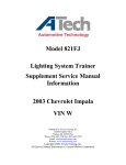
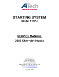
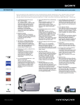
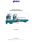
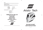
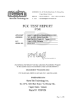
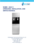
MODEL 830FJ
2003 Chevrolet Impala
Wiper/Washer
Service Manual Information
Table of Contents
Wiper/Washer System Schematic…………………………………………………………1
Connector Pinout – Windshield Washer Fluid Level Switch……………………………..2
Connector Pinout – Windshield Washer Fluid Pump……….…………………………….3
Connector Pinout – Windshield Wiper System Module…….…………………………….4
Diagnostic Starting Point – Wiper/Washer Systems...………………………………...….5
Wiper/Washer System Description and Operation……………………………………...6-7
Symptoms - Wiper/Washer Systems ……..………………………………………………8
Wipers Inoperative - All Modes……………………………………………………….9-11
Wipers Inoperative - One or More Modes……………………………………………12-15
Wiper Blades Do Not Park…………………………………………………………...16-17
Washers Inoperative………………………………………………………………….18-19
Wiper Motor Crank Arm Replacement………………………………………………20-23
Wiper Drive System Module Replacement…………………………………………..24-26
Wiper Arm Replacement……………………………………………………………..27-28
Washer Solvent Container Replacement……………………………………………..29-32
Published by ATech Training, Inc.
12290 Chandler Drive
Walton, KY 41094 USA
Phone: (859) 485-7229 • Fax: (859) 485-7299
Email: [email protected]
Website: www.atechtraining.com
Copyright 2008, ATech Training, Inc.
All Service Manual Information © General Motors Corporation.
1
Wiper/Washer Connector End Views
Windshield Washer Fluid Level Switch
Connector Part Information
• 12162195
• 2-Way F Metri-Pack 150.2 Series Sealed P2S (BLK)
Pin
A
B
Circuit No.
150
99
Wire Color
BLK
BLK/WHT
Function
Ground
Windshield Washer Fluid Level Signal
2
Windshield Washer Fluid Pump
Connector Part Information
Pin
A
B
Wire Color
RED
BLK
• 12052641
• 2-Way F Metri-Pack 150 Series, Sealed (BLK)
Circuit No.
228
350
3
Function
Windshield Washer Pump Control
Ground
Windshield Wiper System Module
Connector Part Information
• 12129126
• 5-Way F Metri-Pack Mixed 150, 280 Series Sealed (BLK)
Pin
A
B
C
D
E
Circuit No.
115
343
92
113
112
Wire Color
BLK
YEL
PPL
DK GRN
GRY
Function
Ground
Accessory Voltage
Windshield Wiper Motor High Speed
Windshield Wiper Switch Signal 1
Windshield Wiper Switch Signal 2
4
Diagnostic Starting Point - Wiper/Washer
Systems
Begin the system diagnosis by reviewing the system Description and Operation. Reviewing the
Description and Operation information will help you determine the correct symptom diagnostic
p rocedure when a malfunction exists. Reviewing the Description and Operation information will also
help you determine if the condition described by the customer is normal operation. Refer to Symptoms Wiper/Washer Systems in order to identify the correct procedure for diagnosing the system and where
the procedure is located.
5
Wiper/Washer System Description and
Operation
Wiper/Washer System Components
The Wiper/Washer System consists of the following components:
z
z
z
z
z
z
Windshield wiper/washer switch
Windshield wiper motor module
Windshield wiper motor
Windshield washer pump motor
Windshield washer fluid level switch
WSW 25A fuse
Wiper/Washer System Operation
The windshield wiper motor module is part of the windshield wiper motor cover and controls wiper
motor operation. The windshield wiper motor is a 2 speed motor and is operated at low speed in all
modes except HIGH. The accessory voltage supply circuit to the windshield wiper motor assembly is
used to operate the wiper motor in all of the low speed modes. The accessory voltage supply circuit to
the windshield wiper/washer switch is used to supply the windshield wiper switch signal circuits and the
wiper motor high speed circuit.
When the wiper/washer switch is in the LOW position voltage is supplied through a 24K ohm resistor
within the switch to the windshield wiper switch signal 2 circuit, and accessory voltage is supplied to the
windshield wiper switch signal 1 circuit. The reduced voltage from the wiper switch signal 2 circuit and
accessory voltage from the wiper switch signal 1 circuit causes the wiper motor module to close the
wiper motor accessory voltage supply circuit to the wiper motor low speed terminal.
Windshield wiper/washer system MIST operation is identical to LOW operation except that the MIST
switch is a press and release type. When the wiper switch is moved to the MIST position and released,
low speed wiper motor operation is started and will continue until 1 cycle is complete. If the wiper
switch is moved to the MIST position and held, the windshield wiper motor will operate in the LOW
mode until the switch is released.
Windshield wiper DELAY operation is a low speed wiper motor function with a variable delay interval
between the wiper motor cycles. The DELAY interval is controlled through a series of resistors within
the wiper/washer switch. During DELAY wiper operation the wiper switch signal 2 circuit is at the same
voltage level used for LOW operation, but the wiper switch signal 1 circuit voltage is reduced through
the DELAY resistors. The windshield wiper motor module uses a capacitor feed by the wiper switch
signal 1 circuit to determine the frequency of the low speed wiper motor cycles. When the wiper switch
signal 1 circuit is at the accessory voltage level as in the LOW switch position, the capacitor charges fast
causing continuous low speed wiper motor operation. The DELAY switch position indicating the
6
longest interval between wiper motor cycles is the switch position with the highest resistance resulting
in low voltage on the wiper switch signal 1 circuit. The low voltage charges the capacitor slowly causing
a long delay interval between wiper motor cycles. As the DELAY switch is turned to positions
indicating more frequent wiper cycles, the resistance through the wiper/washer switch is reduced and the
wiper switch signal 1 circuit voltage increases. When the wiper switch signal 1 circuit voltage increases
the capacitor charges faster and the delay interval between wiper motor cycles decreases.
When the wiper/washer switch is in the HIGH position the accessory voltage to the wiper/washer switch
is closed to the wiper motor high speed circuit. The accessory voltage on the high speed circuit is
supplied to the wiper motor module and is used to operate the wiper motor at high speed. During HIGH
speed wiper motor operation the wiper switch signal 1 and signal 2 circuits are at the LOW speed signal
voltages, but the LOW speed signal circuit inputs to the wiper motor module have no effect on wiper
motor high speed operation.
The windshield wiper/washer system WASH function uses 2 switch contacts within the wiper/washer
switch assembly. One switch contact closes the wiper/washer switch accessory voltage supply circuit to
the wiper switch signal 2 circuit. Accessory voltage on the wiper switch signal 2 circuit causes the wiper
motor module to close the wiper motor accessory voltage supply circuit to the wiper motor low speed
terminal. The WASH command on the wiper switch signal 2 circuit will cause the wiper motor to
operate at low speed for as long as the switch is held in the closed position and approximately 6 seconds
after being released. The other WASH switch contact in the wiper/washer switch is the control circuit to
the windshield washer pump. When the WASH switch is in the held in the closed position the
wiper/washer switch accessory voltage supply circuit is used to operate the windshield washer pump
until the switch is released.
Windshield wiper motor park operation is controlled by the wiper motor module using an input from the
park switch within the wiper motor assembly. When the windshield wiper/washer switch is turned to the
OFF position while the wiper motor is somewhere in mid-cycle, the wiper motor module will continue
to operate the wiper motor until the wipers reach the park position.
Low Washer Fluid Indicator
The low washer fluid indicator is controlled by the instrument panel cluster (IPC) using an input from
the washer fluid level switch. The washer fluid level signal circuit is supplied ignition voltage through a
resistor then monitored within the instrument cluster. The washer fluid level switch is normally open so
the instrument cluster detects ignition voltage on the washer fluid level signal circuit whenever the
washer fluid level is not low. When the washer fluid level reaches the point where the driver should be
informed that the washer fluid is low, the washer fluid level switch closes. When the washer fluid level
switch is closed the washer fluid level signal circuit voltage is pulled low, and the instrument cluster
illuminates the LOW WASHER FLUID indicator. In order to prevent the LOW WASHER FLUID
indicator from flashing due to sloshing in the washer fluid container, the instrument cluster is programed
with a 1 minute delay before changing states of the LOW WASHER FLUID indicator during an
ignition cycle.
7
Symptoms - Wiper/Washer Systems
Important
Review the system operation in order to familiarize yourself with the system functions. Refer to
Wiper/Washer System Description and Operation .
Visual/Physical Inspection
z
z
z
Inspect for aftermarket devices which could affect the operation of the Windshield Wiper/Washer
System.
Inspect the easily accessible or visible system components for obvious damage or conditions
which could cause the symptom.
Inspect the washer fluid reservoir for the proper fluid level.
Intermittent
Faulty electrical connections or wiring may be the cause of intermittent conditions. Refer to Testing for
Intermittent and Poor Connections in Wiring Systems.
Symptom List
Refer to a symptom diagnostic procedure from the following list in order to diagnose the symptom:
z
z
z
z
z
z
z
Low Washer Fluid Indicator Malfunction
Washers Always On
Washers Inoperative
Wipers Always On
Wipers Inoperative - All Modes
Wipers Inoperative - One or More Modes
Wiper Blades Do Not Park
8
Wipers Inoperative - All Modes
Step
Action
Schematic Reference: Wiper/Washer System Schematics
Yes
Connector End View Reference: Wiper/Washer System Connector End Views
Did you review the Wiper/Washer System
1 description and operation and perform the
necessary inspections?
Go to Step 2
1. Turn ON the ignition ON, with the
engine OFF.
2. Operate the windshield wiper/washer
switch through all the switch
2
positions.
Go to Testing for
Intermittent and Poor
Does the windshield wiper/washer system
Connections in Wiring
operate normally?
Systems
1. Turn OFF the ignition.
2. Disconnect the harness connector of
the windshield wiper motor.
3. Turn the ignition ON, with the engine
OFF.
4. Connect a test lamp from the
3
accessory voltage circuit of the
windshield wiper motor to a good
ground.
4
5
No
Go to Symptoms Wiper/Washer
Systems
Go to Step 3
Does the test lamp illuminate?
Connect a test lamp from the accessory
voltage circuit to the ground circuit of the
windshield wiper motor.
Go to Step 4
Go to Step 12
Does the test lamp illuminate?
1. Connect a test lamp from the signal 2
circuit of the windshield wiper switch
to a good ground.
2. Press the windshield washer switch.
Go to Step 5
Go to Step 13
Does the test lamp illuminate?
Go to Step 10
Go to Step 6
9
6
1. Turn OFF the ignition.
2. Disconnect the harness connector of the windshield wiper/washer
switch.
3. Turn ON the ignition, with the engine OFF.
4. Connect a test lamp from the accessory voltage circuit of the
windshield wiper/washer switch to a good ground.
Does the test lamp illuminate?
Test the accessory voltage circuit of the windshield wiper/washer switch for
an open or short to ground. Refer to Circuit Testing or Wiring Repairs in
7 Wiring Systems.
8
9
Did you find and correct the condition?
Test the signal 2 circuit of the windshield wiper/washer switch for a short to
ground. Refer to Circuit Testing or Wiring Repairs in Wiring Systems.
Did you find and correct the condition?
Test the high speed circuit of the windshield wiper/washer switch for a short
to ground. Refer to Circuit Testing or Wiring Repairs in Wiring Systems.
Did you find and correct the condition?
Inspect for poor connections at the windshield wiper motor. Refer to Testing
for Intermittent and Poor Connections and Connector Repairs in Wiring
10 Systems.
Did you find and correct the condition?
Inspect for poor connections at the windshield wiper/washer switch. Refer to
Testing for Intermittent and Poor Connections and to Connector Repairs in
11 Wiring Systems.
Did you find and correct the condition?
Repair an open or a short to ground in the accessory voltage circuit of the
windshield wiper motor. Refer to Wiring Repairs or Connector Repairs in
12 Wiring Systems.
Did you complete the repair?
Repair an open or high resistance in the ground circuit of the windshield
wiper motor. Refer to Wiring Repairs or Connector Repairs in Wiring
13 Systems.
Go to
Step 11
Go to
Step 7
Go to
Step 17
Go to
Step 8
Go to
Step 17
Go to
Step 9
Go to
Step 17
Go to
Step 14
Go to
Step 17
Go to
Step 15
Go to
Step 17
Go to
Step 16
Go to
Step 17
--
Go to
Step 17
Did you complete the repair?
Repair a short to ground in the control circuit of the windshield washer pump.
Refer to Wiring Repairs or Connector Repairs in Wiring Systems.
14
Go to
Step 17
Did you complete the repair?
10
--
--
Replace the windshield wiper motor. Refer to Wiper Motor Replacement .
15
16
Did you complete the replacement?
Replace the windshield wiper/washer switch. Refer to Multifunction, Turn
Signal Switch Replacement in Steering Wheel and Column.
Did you complete the replacement?
Operate the system in order to verify the repair.
17
Did you correct the condition?
11
Go to
Step 17
--
Go to
Step 17
--
System
OK
Go to
Step 3
Wipers Inoperative - One or More Modes
Test Description
The numbers below refer to the step numbers on the diagnostic table.
8. This step tests for continuity through the 24K ohms resistor in the windshield wiper/washer
switch. The connector behind the instrument panel knee bolster is suitable for performing this
step.
9. This step tests for continuity through the delay resistors in the windshield wiper/washer switch.
The measured resistance will change in sequence from high to low as the delay speed is increased.
The connector behind the instrument panel knee bolster is suitable for performing this step.
Value
Step
Action
(s)
Schematic Reference: Wiper/Washer System Schematics
Yes
No
Connector End View Reference: Wiper/Washer System Connector End Views
Did you review the Wiper/Washer
Go to Symptoms 1 System Description and Operation and
-Wiper/Washer
perform the necessary inspections?
Systems
Go to Step 2
1. Turn the ignition ON.
2. Operate the windshield
wiper/washer switch through all
the switch positions.
2
-Go to Testing for
Intermittent Conditions and
Does the windshield wiper/washer
Poor Connections in
Go to Step 3
system operate normally?
Wiring Systems
Do the windshield wipers operate in
3
-Go to Step 5
Go to Step 4
the high speed mode?
1. Disconnect the windshield wiper
motor connector.
2. Connect a test lamp from the
windshield wiper motor high
speed circuit terminal to ground.
3. Turn the ignition ON.
4
-4. Operate the windshield
wiper/washer switch to the high
speed position.
Does the test lamp illuminate?
Go to Step 16
12
Go to Step 10
5
1. Disconnect the windshield wiper motor connector.
2. Connect a test lamp from the windshield wiper motor accessory
voltage supply circuit terminal to ground.
3. Turn the ignition ON.
Does the test lamp illuminate?
1. Connect a test lamp from the windshield wiper switch signal 2
circuit terminal to ground.
6 2. Press the windshield washer switch.
7
8
Does the test lamp illuminate?
1. Connect a test lamp from the windshield wiper switch signal 1
circuit terminal to ground.
2. Operate the windshield wiper/washer switch to the following
positions:
- MIST
- LO
- HI
Does the test lamp illuminate in the listed switch positions?
1. Disconnect the windshield wiper/washer switch connector.
2. Measure the resistance through the windshield wiper/washer
switch from the signal 2 circuit terminal to the accessory voltage
supply circuit terminal in the switch side connector.
3. Operate the windshield wiper/washer switch to the following
positions:
- MIST
- INT
- LO
- HI
Is the resistance at or near the specified value in all the listed switch
positions?
13
-Go to
Step 6
Go to
Step 11
Go to
Step 7
Go to
Step 12
Go to
Step 8
Go to
Step 13
--
--
24K
ohms
9
1. Measure the resistance through the windshield wiper/washer
switch from the signal 1 circuit terminal to the accessory
voltage supply circuit terminal in the switch side connector.
2. Operate the windshield wiper/washer switch through all of the
delay positions.
Does the resistance remain within the specified values from high to
low as the delay speed is increased?
Test the windshield wiper motor high speed circuit for an open or
high resistance. Refer to Circuit Testing and Wiring Repairs in
10 Wiring Systems.
Did you find and correct the condition?
Repair the windshield wiper motor accessory voltage supply circuit
for an open or high resistance. Refer to Wiring Repairs in Wiring
11 Systems.
Is the repair complete?
Test the windshield wiper switch signal 2 circuit for an open or short
to ground. Refer to Circuit Testing and Wiring Repairs in Wiring
12 Systems.
Did you find and correct the condition?
Test the windshield wiper switch signal 1 circuit for an open or short
to ground. Refer to Circuit Testing and Wiring Repairs in Wiring
13 Systems.
Did you find and correct the condition?
Inspect for poor connections at the windshield wiper/washer switch.
Refer to Testing for Intermittent Conditions and Poor Connections
14 and Connector Repairs in Wiring Systems.
Did you find and correct the condition?
Replace the windshield wiper/washer switch. Refer to
Multifunction, Turn Signal Switch Replacement in Steering Wheel
15 and Column.
Is the repair complete?
Inspect for poor connections at the windshield wiper motor. Refer to
Testing for Intermittent Conditions and Poor Connections and
16 Connector Repairs in Wiring Systems.
Did you find and correct the condition?
14
38K 690K
ohms
Go to
Step 16
Go to
Step 14
Go to
Step 18
Go to
Step 14
Go to
Step 18
--
Go to
Step 18
Go to
Step 14
Go to
Step 18
Go to
Step 14
Go to
Step 18
Go to
Step 15
Go to
Step 18
--
Go to
Step 18
Go to
Step 17
--
--
--
--
--
--
--
17
Replace the windshield wiper motor module. Refer to Wiper Motor
Cover Replacement .
Is the repair complete?
Operate the system in order to verify the repair.
18
Did you correct the condition?
15
-
Go to
Step 18
--
System OK
Go to
Step 3
Wiper Blades Do Not Park
Step
Action
Schematic Reference: Wiper/Washer System Schematics
Yes
No
Connector End View Reference: Wiper/Washer System Connector End Views
DEFINITION: This table diagnoses the wipers operate normally but will not return to the park position
when the wiper operation is cancelled.
Did you review the Wiper/Washer System
Go to Diagnostic
1 Description and Operation and perform
Starting Point the necessary inspections?
Go to Step 2
Wiper/Washer Systems
1. Turn ON the ignition, with the
engine OFF.
2. Move the wiper switch to the LO
position.
3. Move the wiper switch to the OFF
2
position.
Go to Testing for
Intermittent and Poor
Connections in Wiring
Do the front wipers advance to the park
Systems
Go to Step 3
position?
1. Turn the ignition switch to the RUN
position.
2. Turn the wiper switch to OFF.
3. Disconnect the wiper/washer switch
3
connector.
4
Do the wipers park?
At the wiper/washer switch connector,
measure the voltage of the windshield
wiper switch signal 2 circuit.
Does the voltage measure greater than
1.0 volts?
16
Go to Step 7
Go to Step 4
Go to Step 5
Go to Step 8
5
6
7
1. Reconnect the wiper/washer switch connector.
2. Disconnect the wiper motor connector.
3. Measure the voltage of the windshield wiper switch signal 2 circuit.
Does the voltage measure greater than 1.0 volts?
Repair a short to battery positive voltage in the windshield wiper switch
signal 2 circuit. Refer to Circuit Testing and Wiring Repairs in Wiring Systems.
Did you find and correct the condition?
Replace the wiper/washer switch. Refer to Multifunction, Turn Signal Switch
Replacement in Steering Wheel and Column - Tilt.
Did you complete the replacement?
Replace the wiper motor cover. Refer to Wiper Motor Cover Replacement.
8
Did you complete the replacement?
Operate the system in order to verify the repair.
9
Go to
Step 6
Go to
Step 8
Go to
Step 9
--
Go to
Step 9
--
Go to
Step 9
--
System
OK
Did you correct the condition?
17
Go to
Step 2
Washers Inoperative
Step
Action
Schematic Reference: Wiper/Washer System Schematics
Yes
Connector End View Reference: Wiper/Washer System Connector End Views
Did you review the Wiper/Washer System
1 Description and Operation and perform the
necessary inspections?
Go to Step 2
1. Turn the ignition ON.
Go to Testing for
2. Press the windshield washer switch.
Intermittent and Poor
2
Connections in Wiring
Do the windshield washers operate normally?
Systems
1. Disconnect the windshield washer pump
connector.
2. Connect a test lamp across the washer
pump harness connector terminals.
3
3. Turn the ignition ON.
4. Press the windshield washer switch.
No
Go to Symptoms Wiper/Washer
Systems
Go to Step 3
Go to Step 8
Go to Step 4
4
Does the test lamp illuminate?
Test the windshield washer pump ground circuit
for an open or high resistance. Refer to Circuit
Testing and Wiring Repairs in Wiring Systems.
Go to Step 10
Go to Step 5
5
Did you find and correct the condition?
Test the windshield washer pump control circuit
for an open or high resistance. Refer to Circuit
Testing and Wiring Repairs in Wiring Systems.
Did you find and correct the condition?
Inspect for poor connections at the windshield
wiper/washer switch. Refer to Testing for
Intermittent and Poor Connections and Connector
Repairs in Wiring Systems.
Go to Step 10
Go to Step 6
Did you find and correct the condition?
Go to Step 10
Go to Step 7
6
18
7
Replace the windshield wiper/washer switch. Refer to Multifunction, Turn
Signal Switch Replacement in Steering Wheel and Column.
Is the repair complete?
Inspect for poor connections at the windshield washer pump. Refer to Testing
for Intermittent and Poor Connections and Connector Repairs in Wiring
8 Systems.
Did you find and correct the condition?
Replace the windshield washer pump. Refer to Washer Pump Replacement .
9
Is the repair complete?
Operate the system in order to verify the repair.
10
Did you correct the condition?
19
Go to
Step 10
--
Go to
Step 10
Go to
Step 9
Go to
Step 10
--
System
OK
Go to
Step 3
Wiper Motor Crank Arm Replacement
Tools Required
• J 39232 Wiper Transmission Separator
• J 39529 Wiper Transmission Installer
Removal Procedure
1. Remove the air inlet grille panel. Refer to Air Inlet Grille Panel Replacement in Body Front End.
2. Remove the wiper motor water deflector. Refer to Wiper Motor Water Deflector Replacement.
3. Using the J 39232, disconnect the wiper transmission from the wiper motor crank arm.
20
4. Remove the wiper motor crank arm cover.
5. Remove the wiper motor crank arm screw.
6. Remove the wiper motor crank arm from the wiper motor.
Installation Procedure
1. Before installing the wiper motor crank arm, the wiper motor must be in the inner wipe position of
the delay mode.
2. Position the wiper motor crank arm onto the wiper motor.
3. Measure the gap between wiper motor crank arm and the bracket tab. If the gap is not 4-8 mm
(0.157-0.314 in), remove the wiper motor crank arm and repeat installation.
21
Notice: Refer to Fastener Notice in Cautions and Notices.
4. Install the wiper motor crank arm screw .
Tighten
Tighten the screw to 16 N·m (12 lb ft).
5. Install the wiper motor crank arm cover.
6. Using the J 39529 , install the wiper transmission to the wiper motor crank arm.
7. Install the air inlet grille panel. Refer to Air Inlet Grille Panel Replacement in Body Front End.
8. Install the wiper motor water deflector. Refer to Wiper Motor Water Deflector Replacement.
22
9. Operate the windshield wipers and inspect for proper operation.
23
Wiper Drive System Module Replacement
Tools Required
• J 39232 Wiper Transmission Separator
• J 39529 Wiper Transmission Installer
Removal Procedure
1. Remove the air inlet grille panel. Refer to Air Inlet Grille Panel Replacement in Body Front End.
2. Remove the wiper motor water deflector. Refer to Wiper Motor Water Deflector Replacement.
3. Using the J 39232 , disconnect the wiper transmission from the wiper motor crank arm to aid in
the removal of the wiper drive system module.
24
4. Remove the wiper drive system module screws.
5. Disconnect the wiper motor electrical connector.
6. Remove the wiper drive system module from the vehicle.
Installation Procedure
1. Position the wiper drive system module to the vehicle.
2. Connect the wiper motor electrical connector.
Notice: Use the correct fastener in the correct location. Replacement fasteners must be the correct
part number for that application. Fasteners requiring replacement or fasteners requiring the use of
25
thread locking compound or sealant are identified in the service procedure. Do not use paints,
lubricants, or corrosion inhibitors on fasteners or fastener joint surfaces unless specified. These
coatings affect fastener torque and joint clamping force and may damage the fastener. Use the
correct tightening sequence and specifications when installing fasteners in order to avoid damage
to parts and systems.
3. Install the wiper drive system screws.
Tighten
Tighten the screws to 10 N·m (89 lb in).
4.
5.
6.
7.
Using the J 39529 , Install the wiper transmission to the wiper motor crank arm.
Install the wiper motor water deflector. Refer to Wiper Motor Water Deflector Replacement .
Install the air inlet grille panel. Refer to Air Inlet Grille Panel Replacement in Body Front End.
Inspect the wipers for proper operation.
26
Wiper Arm Replacement
Tools Required
J 39822 Wiper Arm Puller
Removal Procedure
1.
2.
3.
4.
5.
6.
7.
Turn the ignition ON.
Turn the wiper switch to DELAY.
Turn the ignition OFF when the wiper arms are paused at the bottom of the wipe pattern.
Disconnect the washer hose from the wiper arm.
Remove the wiper arm nut cover.
Remove the wiper arm nut.
Using the J 39822, remove the wiper arm from the wiper transmission.
27
Installation Procedure
1. Install the wiper arms onto the wiper transmission.
2. Hold the measuring device at a 90 degree angle to the wiper blade while maintaining the
following distances:
- Right arm: 97-107 mm (3.82-4.21 in) from the end of the wiper arm to the air inlet screen
- Left arm: 125-147 mm (4.92-5.78 in) from the wiper blade tip to the air inlet screen
3. Apply Threadlocking compound, GM P/N 89021297 (Canadian P/N 10953488) or equivalent, to
the wiper arm nut.
Notice: Refer to Fastener Notice in Cautions and Notices.
4. Install the wiper arm nut.
Tighten
Tighten the nut to 30 N·m (22 lb ft).
5. Install the wiper arm nut cover.
6. Connect the washer hose to the wiper arm.
7. Operate the windshield wipers and inspect for proper operation.
28
Washer Solvent Container Replacement
Removal Procedure
1. Drain the washer solvent from the washer solvent container.
2. Remove the washer solvent container filler neck. Refer to Washer Solvent Container Filler Neck
Replacement.
3. Remove the right headlamp assembly. Refer to Headlamp Assembly or Headlamp Bulb and/or
Cornering, Sidemarker, Park, Turn Signal Bulb Replacement in Lighting Systems.
4. Remove the washer solvent container screws.
5. Remove the front fender liner. Refer to Front Fender Liner Replacement in Body Front End.
29
6. Disconnect the washer pump hose.
7. Disconnect the washer pump electrical connector.
8. Disconnect the washer solvent level sensor electrical connector.
9. Remove the washer solvent container bracket screw.
10. Remove the washer solvent container from the right frame rail.
Installation Procedure
30
1. Position the washer solvent container to the right frame rail.
Notice: Refer to Fastener Notice in Cautions and Notices.
2. Install the washer solvent container bracket screw.
Tighten
Tighten the screw to 10 N·m (89 lb in).
3. Connect the washer solvent level sensor electrical connector.
4. Connect the washer pump electrical connector.
31
5. Connect the washer pump hose.
6. Install the front fender liner. Refer to Front Fender Liner Replacement in Body Front End.
7. Install the washer solvent container screws.
Tighten
Tighten the screws to 10 N·m (89 lb in).
8. Install the right headlamp assembly. Refer to Headlamp Assembly or Headlamp Bulb and/or
Cornering, Sidemarker, Park, Turn Signal Bulb Replacement in Lighting Systems.
9. Install the washer solvent container filler neck. Refer to Washer Solvent Container Filler Neck
Replacement .
10. Fill the washer solvent container with washer solvent.
32