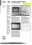
1
TEK
~
300
--- MHz AND 150
--- MHz
2400
SERIES
FOUR
...:
TRACE
OSCILLOSCOPES
With compliments
Helmut Singer Elektronik
www.helmut-singer.com
2465/2445
300 MHz Bandwidth at the Probe Tip (2465)
150 MHz Bandwidth
at the Probe Tip (2445)
"
500 ps/dlv
1 ns/div
Sweep Rate (2465)
Sweep Rate (2445)
Time Interval Resolution to 20 ps
Four Independent Channels
2 mV/div Vertical Sensitivity
V It A T "
C
.. 0 S", Ime ursors
Adjustable
Channel1/Channei
2 Delay
Matching
Advanced Triggering System Featuring tlie
"Hands
Off" Auto Level Trigger
M" .
T.
"
B d "
Inlmum nggenng an WIdth 0f 500 MH z
(2465) and 250 MHz (2445)
B Sweep Displays the A Sweep Trigger
Event
-A
50 Q/1 MQ Inputs with 50 Q Protection
CRT Readout
Calibrated Horizontal Variable
Scale Factors
Trigger Level
Voltage, Time, Frequency,
Phase and Ratio Measurements
M
-
, ode Indicators
Three Channel X-V Display
Rugged Design
Th
V
ree
W
ear
ty
arran
F
-
"
Ive
V
O
ear
.
ptlon
The new 300 MHz 2465 and 150 MHz 2445 repre"
sent the state-of-the-art and a higher standard in
value for today's portable oscilloscopes. They
make better measurements faster than any previous portable oscilloscopes. Cursors avoid interpretation errors and increase operator productivity. Four channels give complete views to simplify
complex
measurements
The front panel
Channel1/Channel 2 delay matching adjustment
eliminates the effects of probe and vertical channel delay differences.
The 2465/2445 provide 1% horizontal accuracy
and 2% vertical accuracy for greater measurement confidence. On-screen vertical and horizontal cursors deliver immediate measurements of
voltage; time, frequency, ratio and phase with
CRT readout. CRT readouts also include: scale
factors for easy setup and interpretation of waveforms, including a calibrated horizontal variable;
trigger level readout for predictable triggering on
logic signals and transient events; and mode
indicators, such as add, invert, bandwidth limit,
and more
TEK
300 MHz AND 150 MHz
FOUR TRACE OSCILLOSCOPES
2400 Series scopes can trigger on any or all of the
four channels. The new Auto Level mode provides "hands off" triggering on any pulse width or
waveform at repetition rates down to 50 Hz.
Single Sequence Trigger mode sequentially
sweeps through each channel displayed when
triggered, then flashes the CRT readouts and
graticule illumination.
The B sweep can display any portion of the
A sweep, including the A sweep trigger event.
This provides accurate delay and delta time
measurements from the "first pulse" and allows
the user to examine the A trigger event in detail.
In strong testimony of the incomparable reliability
of the 2000 Family oscilloscopes, Tek offers the
industry's first three year warranty: All labor and
parts, including CRT, excluding probes. And then,
beyond the "basic three years" of warranty coverage, Tek will extend your service coverage up to
five years, offering you a choice of three practical
service plans to meet your specific service
needs
Input Z (1 Mil)
-
1 M!J :t 0.5% shunted by 15 pF. :t2 pF. The
maximum input voltage is 400 V (dc + peak ac); 800 V pop ac
at 10 kHz or less
Input Z (SOII) - 50 II :t 1%, with a vswr from dc to 300 MHz
of 1.3 to 1 or less. The maximum input voltage is 5 V RMS. or
0.5 W/s during any 1 s interval for instantaneous voltages from
5Vt050V.
Cascaded Operation - CH 2 Signal Out is coupled into CH 1
input. Bandwkjth is dc to 50 MHz or greater and the deflection
factoris400"V/div:t10%.
Deflection
CHANNEL 3 AND CHANNEL 4
Factor - 0.1 V/div and 0.5 V/div :t
100/0.
Input Z - 1 M!J :t 1%.shuntedby 15 pF :t3 pF.
Maximum Input Voltage
-
400 V (dc + peak ac): 800 V pop
ac at10 kHz or less.
FrequencyResponse(Bandwidthand Risatimer'
With Standard
Accessory
Probe
Dc to
1.
With 50 II
External
tion
MHz.
14ns
2465
-1S"C to
+3S"C
2465
+3S"C to
Dc to 250 MHz
MHz.
+SS"C
14 ns
.75 ns
2445
-1S"C to
Dc to 150 MHz
MHz,
+55"C
2.33 ns
.33 ns
°, With a 6 div signal, from a 50!l tenninated source.
Channel Isolation -
50:1 or greater attenuation of the de-
selected channel at 100 MHz with an 8 div input signal
ALL CHANNELS
Low
Frequency
Linearity
- 0.1 div or less compressionor
expansion of a 2 diY, center-screen signal when positioned
anywhere within the graticule area.
Bandwidth Limiter - Reduces upper 3 dB bandpass to a limit
of 13 MHz to 24 MHz.
Vertical Signa' Delay -
CALIBRATED SWEEP DELAY
~Time Accuracy - Time intervals measured with delayed
B Sweep with both delays set at 0.5% or more of full scale
from minimum delay (no '?" displayed in readout): :t 0.3% of
time interval +01% of full scale
Delay Accuracy - A Sweep Trigger Point to Start of
B Sweep: :t (0.3% of delay
scale)-+O ns, -25 ns
played before the triggering event is displayed on the A sweep
for settings ..10 ns/div At least 10 ns of delay is dIsplayed at
5 nsldiv for the 2465.
+ 0.6%
of full
~ Time Readout Resolution
2465: Greater of either 10 ps or 0.025% full scale.
2445: Greater of either 20 ps or 0.025% full scale.
~ Time Range
-
:t 10 times the A Sec/Div switch set1ing.
Delay Pickoff Jit1er
-
Within 0004% (one part or less in
25,000) of the maximum available delay, plus 100 ps
Delay Time Position Range - 0 to 9.95 times the A Sec/Div
switch set1ing. Main sweep triggering event is observable on
delayed sweep with minimum delay set1lng.
TRIGGERING
The minimum p-p signal amplitude for stable triggering is stated for CH 1 or CH 2 source. The signal amplitude for CH 3 or
CH 4 source is one-half of CH 1 or CH 2 source specification
For multiple chanr)el source (Alternate Vertical Mode) add 1 div
to the single channel source specif~ation.
Dc Coupled - 035 div from dc to 50 MHz, increasing to 1 div
at 500 MHz (250 MHz for 2445).
Noise Reject Coupled -
A voltage level-sensing hysteresis
window defined by two levels of p-p signal amplitude. For signals within the vertical bandwid1h, triggering will not occur (signal reJec1) with ..0.4 div Stabie triggering will occur with
..1.2 div from dc to 50 MHz, increasing to 3 div at 500 MHz
(250 MHz for 2445).
Ac Coupled - 0.35 div from 60 Hz to 50 MHz, increasing to
1 div at 500 MHz (250 MHz from 2445). At1enuates signals below 60 Hz
HF Reject Coupled -
At least 30 ns of the signal is dis-
setting
LF Reject Coupled -
0.5 div from dc to 30 kHz.
0.5 div from 80 kHz to 50 MHz, increas-
ing to 1 div at 500 MHz (250 MHz for 2445).
Jitter - Less than 50 ps at 300 MHz with A and B Sec/Div set
for 5 ns/div sweep and 10X Mag on (100 ps at 150 MHz and
10 nsldiv for 2445).
Chopped Mode Switching Rate - 2.5MHz;; 0.2% from
2 !tsldiv to 20 !ts/div (1.25 MHz dual channel cycle rate). At All
Level Control Range - CH 1 or CH 2: :t 18 times the VolUDiv
OtherSweepSpeeds:1 MHz ;;0.2% (500 kHz dual channel set1ing CH 3 or CH 4 :t 9 times the Volts/DiY set1ing
cycle rate).
Level Control Readout and Range Accuracy (for Triggering
Signals with Transition Times >20 ns) - CH 1 or CH 2
HORIZONTAL
DEFLECTION
SYSTEM
Horizontal Display Modes
A. A Intensified, B Delayed, AlSource (Dc Coupled): +15"C to +35"C is within :!:[3% of
ternate (A Intensified and B Delayed), B ends A for increased
set1ing +3% of p-p signal +02 div +(05 mV x probe attenuaintensity in the delayed mode. For X-Y operation Channel 1
tion factor)] -15"C to +55"C (excluding + 15"C to +35"C)
supplies the X-axis (horizontal) deflection.
add (1.5 mV x probe at1enuation factor). For noise reject coupled add :t 0.6 div to the dc coupled specifIcation. CH 3 or
A Sweep Time Base Range
CH 4 Source (Dc Coupled): Within :t[3% of set1ing +4% of
2465: 0.5 s/div to 5 ns/div in a 1-2-5 sequence of 25 steps.
p-p signal +01 div +(0.5 mV x probe attenuation factor)]. For
X10 Mag feature extends maximum sweep speed to
noise reject coupled add 03 div.
500 ps/div
2445: 1 s/div to 10 ns/div in a 1-2-5 sequence of 25 steps.
Slope Selection - Conforms to trigger-source waveform or
X10 Mag feature extends maximum sweep speed to 1 ns/div
ac power-source waveform
-
~
B Sweep Time Baae Range
2465: 50 ms/div to 5 ns/div in a 1-2-5 sequence of 22 steps.
X10 Mag feature extends maximum sweep speed to
500 ps/div.
2445: 50 ms/div to 10 ns/div in a 1-2-5 sequence of 21 steps.
X10 Mag feature extends maximum sweep speed to 1 ns/div
.r Risetlme calculated from: Bandwidth x Risetime = 0.35
Ac Coupled
Lower
-3
dB Point
-
With 1X Probe:
10 Hz or
less With 10X Probe 1 Hz or less
Common-Mode Rejection Ratio - At least 20:1 at 50 MHz
for common-mode signals of 8 diY or less, with Var Volts/DiY
control adJusted tor best CMRR at 50 kHz at any Volts/Diy
setting ..5 mV. At least 20:1 at 20 MHz at 2 mV/diY.
Channell.olation - For an 8 diY Input Signal trom 2 mV/diy
to 500 mV/diY, with Equal Volts/DiY Settings on Both Channels: 1001 or greater attenuation of the deselected channel at
100 MHz; 501 or greater attenuation at 300 MHz (150 MHz
for 2445)
CH 1 to CH 2 Signal Delay - The displayed delay is adjustable through a range ot at least:!: 500 ps
-
Continuously variable and calibrated
between settings of the Sec/Div switch Extends slowest
A sweep speed to 1.5 s/div Operates in conjunction with the
A Sec/Div switch when A and B are locked together; operates
in conjunctIon with the B SeclDiv switch when A and B are not
locked together.
Variable
Time Control
Auto Level Mode Maximum Triggering Signal Period - With
A Sec/Div Switch Setting less than 10 ms: At least 20 ms
A Sec/Div Switch Setting from 10 ms to 50 ms: At least four
times the A Sec/Div switch settIng A Sec/Div Switch Setting
from 100 ms to 500 ms: At least 200 ms
Auto Mode Maximum Triggering Signal Period - With
A Sec/Div Switch Setting Less than 10 ms: At ~ast 80 ms
A Sec/Div Switch Setting from 10 ms to 50 ms: At least 16
times the A SeclDiv switch setting A Sec/Div Switch Setting
from 100 ms to 500 ms: At least 800 ms.
Auto Level Mode Trigger Acquisition Time - 8 to 100 times
the Auto Level mode maximum triggering-signal period. depending on the triggering-signal period and waveform.
A Trigger Holdoff - An adjustable control permits a stable
presentation of repetitive complex waveforms. ExtendS
A sweep holdoff to at least 10 times Sec/Div setting. Fully
clockwise B sweep ends A sweep.
Voltage Ranges
-
AC POWER SOURCE
115V: 90V to 132V 230 V: 180V to
250 V.
ziploc
Source Frequency -
48 Hz to 440 Hz.
Power Consumption -
Typical: 70 W (140 VA). Maximum:
02 div or less compres-
Electromagnetic
toned within the display area
Part 2
Compatibility
--
Meets Mll-STD-46tS
MIL-STD-461 B
ACCESSORIES
CRT filter
(378-0199-00);
clear plastic CRT filter (378-0208-00);
snap ac-
cessory
(016-0692-00);
pouch
pouch (016-0537-00);
ator manual;
power cord (161-0104-00).
service manual;
service
Rackmounted
2 A.250 V fuse (159-0021-00);
manual;
instruments
slide out assemblies,
and reference
and reference
does not include
The 2465 and 2445 oscilloscopes
div ~Time: At least the center 9.6 horizontal div
Altitude
following
power Down Memory
At powerdown the front panelsettings will be stored in memory (EAROM) providing ..10 s of
operating time has occurred
ating temperature decreases 1'C for each 1.000 It above
5,000 It. Nonoperating: To 15 200 m (50.000 It).
Humidity - Operating and Nonoperating: Stored at 95% rela-
Z-AXIS INPUT
Sensitivity - Positive voltage decreases intensity. Dc to
2 MHz: +2 V blanks a maximum intensity trace. 2 MHz to
20 MHz: +2 V modulates a normai intensity trace.
tive humidity for 5 cycles (120 hours) from +30'C to +60'C,
with operational performance checks at +30'C and +55'C,
Dripproof
With Cover On Meets MIL-T-28800CPara.
-
-
Input Resistance
9 kIJ !: 10%.
MaximumInput Voltage
-
:t 25 V peak; 25 V pop ac at
10 kHz or less
SIGNAL OUTPUTS
Calibrator - Output Voitage and Current: 0.4 V :t t% into a
1 MI! load. 0.2 V :t 15% into a 50 \J load, or B mA :t t .5% into
a short circuit. with A Sec/Div switch set to t ms/div Repetilion Period: Two times the A Sec/Div switch setting within the
range of 200 ns to 200 ms Accuracy is :t O.1% measured with
!he Sgl Seq A Trigger Mode selected. Symmetry: Duration of
high portion of output cycle is 50% of the output period :t (lesser of 500 ns or 25% of period). Jitter of Pulse Period or Pulse
WKjth: 10 ns or less
CH 2 Signal Dut - Dutput Voltage: 20mV/div :t10% into
1 MQ, 10mV/div :t10% into 50Q Offset: :t10mV into 50Q
when dc balance has been performed within :t 5. C of the operating temperature
A Gate Out and B Gate Out
-
Output
Voltage
2.4 V to 5 V
positive going pulse. starting at 0 V to 0.4 V Output Drive: Will
supply 400 "A during HI state; will sink 2 mA during LO state
CRT
READOUT
AND
-
45553.
Vibration
-
Operating: 15 minutes along each of three axes
at a total displacement of 0.025 inch pop (4 g at 55 Hz), with
frequency varied from 10 Hz to 55 Hz in one-minute sweeps.
Held 10 minutes at each major resonance, or if none existed,
held 10 minutes at 55 Hz (75 minutes total test time).
Shock - Operating and Nonoperating: 50 g's, half-sine,
11 ms duration, three shocks on each face, for a total of
18 shocks.
Transit Drop - Not in Shipping Package: 12 inch drop on
card
Opt","
1 R:
hardware
and
pouch.
INSTRUMENT
Option
factory
1R
-
Rackmount
Option 11
-
installed
OPTIONS
can be configured
with the
options
Configure Oscilloscope for
RearPanelProbePower
Connectors (2465 Only)
Option22 Two Additional P6131 Probes
2465 Option 1R and Option 11 Extender CablesOrder 020-0103-00.
2465/2445 Option 1R Extender Cables
-
Order 020-0104-00.
INTERNATIONAL POWER CORDS AND PLUG OPTIONS
Option A1 - Universal Euro 220 V/16 A, 50 Hz
Option A3
-
Australian240V/10 A, 50 Hz
Option A4
-
North American 240 V/15 A, 60 Hz
Option A2
UK 240 V/13 A, 50 Hz
each corner and each face (MIL-T-28800C. para 4.5.542)
Option A5 -
Bench Handling -
WARRANTY-PLUS SERVICE PLANS-Refer to page 41
M1
(2465)2 Calibrations
M1 (2445) 2 Calibrations
M2
(2465)2 YearsServiCe
M2
(2445) 2 Years ServiCe
M3
(2465) 2 Years Service and 4 Calibrations
M3
(2445) 2 Years Service and 4 Calibrations
With and Without Cabinet Installed:
MIL.STD-810C. Method 516, Procedure V (MIL.T-28800C,
para 45.5.43).
Topple - Operating and Cabinet Installed: Set on rear feet
and allowed to topple over onto each of four adjacent faces.
Packaged Transportation Drop - Meets the limits of the National Safe Transit Association Test Procedure 1A-B-2;
10 drops of 36 inches.
Packaged Transport8tion Vibr8tion - Meetsthe limItsof the
National Safe Transit Association Test Procedure 1A-B-1; excursion of 1 inch pop at 4.63 Hz (11 g) for 30 minutes.
WAVEFORM INFORMATION
l
2465 oper-
ORDERING INFORMATION
2465 300 MHz Oscilloscope
2445 150 MHz Oscilloscope
Temperature - Operating:-1S.C to +SS.C. Nonoperating:
-62.C to +8S.C
- Operating:
OperatingTo 4600m (1S.000
(15,000It).
It) Maximumoper-
2445 op-
card
also include mounting
CursorPositionRange- ~V At least the center 76 vertical
CURSOR AND FRONT PANEL DISPLAY
(010-6131.01);
blue plastic
erator manual;
ENVIRONMENTAL CHARACTERISTICS
The 2465/2445 Oscilloscopes meet or exceed the environmental requirements of Mll- T -28800C for Type III. Class 3. Style C
equipment. tested for humidity 4.5.5.12.2. low temperature
455 13 and high temperature 4.55.1.4
Safety - Ul
UL 1244 and CSA approval.
siOI1or expansion of a 2 div. center-screen signal when posi-
accessory
front cover (200.2742.00);
120W(180VA)
X Axil Low-Frequency Linearity -
INCLUDED
Two P6131 10X 13 m probes with accessories
Switzerland 220 V/10 A, 50 Hz
---
OPTIONAL ACCESSORIES
Protective
Waterproof
Blue Vinyl
-
Cover
Order 016-0720-00
Probe Package - P6131 for Use with Channels 3 or 4
Order 010-6131-01
P6230 - 10X Bias/Offset Active Probe.
Tektronix 24S5 3OOMHzOSOLLOSCOPel
Order 010-6230-01
Rackmounting Conversion Kit
-
Order 016-0691-00
Rear Support Kit -
For Use with Rackmounted Instruments
required to meet MIL-T-28800C Order 016-0096-00
Polarized Collapsible Viewing Hood
Order 016-0180-00
-
Folding Light Shielding Viewing Hood
Order 016-0592-00
Collapsible Binocular Viewing Hood
Order 016-0566-00
trigger source. trigger voltage level, and :.time results. The low.
er area displays the selected volts/div and seconds/div scale
factors and that bandwidth limit and holdoff are activated.
DISPLAY
CRT
80 mm x 100 mm (8 cm x 10 cm)
Standard Phosphor
GH (P31) is standard.
Nominal Accelerating Potential - 16 kV
-
-
Rackmount 2465 Option tR. comes complete with slide-out
chassis tracks.
-
Oscilloscope Camera -
See C-30B Option 01.
SCOPE-MOBILE Cart -
See 2000 or 200C.
Carrying Strap -
Your eyes never have to leave the screen to obtain front panel
settings and meaurement results
In the CRT example above, the top area of the display provides
-
Order 346-0199-00