1
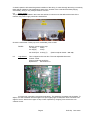
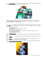
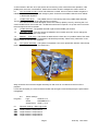
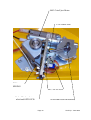
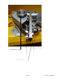
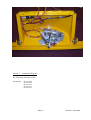
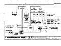
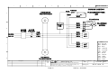
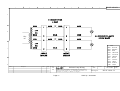
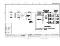
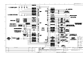
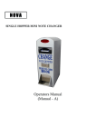
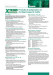
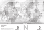
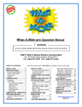
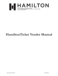
USA TICKET
SERVICE MANUAL
Produced by ;
Harry Levy Amusement Contractor Ltd
Pysons Road Industrial Estate
Broadstairs
Kent
CT10 2LF
England
Tel +44 1843 866464
Fax +44 1843 860144
Distributed in the United States of America by ;
Coastal Amusement Distributors Inc.
601 Prospect Street
Lakewood N.J. 08701
Tel 908 905 6662
Fax 908 905 6815
CONTENTS
Section 1 - Information
Section 2 - General service
2.1 Replacement parts
2.2 Ticket dispensers
2.3 Payout hoppers
Section 3 - Description of game
3.1 Attract mode
3.2 The game
Section 4 - Specification
4.1 Dimensions
4.2 Electrical ratings
4.3 Error codes and alarm signals
Section 5 - Access
5.1 General
5.2 Playfield
5.3 Coin entry compartment
5.4 Lower cabinet
5.5 Cashbox
5.6 Top sign
5.7 Hoppers
Section 6 - Electrical system
6.1 General troubleshooting
6.2 Wiring check
6.3 Power supply
6.4 Logic Board
6.5 Coin ejector board
6.6 Tilt
6.7 Hopper microphone
6.8 Speaker
6.9 Lighting
6.10 Paddle drive motor and cut out switch
6.11 Coin and ticket counter
Section 7 - Mechanical systems
7.1 Paddle motor drive
7.2 Paddle assembly
7.3 Coin entry chute
7.5 Diverter
7.6 Coin ejector assembly
Section 8 – Dipswitch settings
8.1 Logic board
8.2 Coin ejector board
Section 9 - Troubleshooting
Section 10 – Spare Parts List
Section 11 – Schematic Diagrams
Page 2
Surfs Up June 2002
1. INFORMATION.
1.1 This Manual is intended as a guide to the operation, servicing, faultfinding and repairs on the Surfs
Up machines.
1.2 All details and specifications shown in this manual are correct at the time of print. The right to
modify equipment, change specifications and instructions at any time, without notice is reserved as part
of Harry Levy Amusement Contractor Ltd policy of continuous development and improvement.
1.3 Only qualified, professional personnel should gain entry to the machine, and the author or Harry
Levy Amusement Contractor Ltd. accepts no liability for any damage or injury arising from the use of this
service manual.
2. GENERAL SERVICING
2.1
Replacement Parts.
It is of mutual interest that equipment is kept in excellent working condition, therefore when requested
please order original replacement parts from your distributor or Harry Levy Amusement Contractor Ltd.
The parts list is at the back of this manual.
2.2
Ticket dispensers.
The ticket dispenser is a Deltronic DL 1275 unit. Please refer to the yellow manual for ticket machine
adjustment and electrical specification.
2.3
Hopper. (USA)
WARNING: DO NOT DISCONNECT OR RECONNECT UNLESS THE MACHINE IS SWITCHED OFF
This is an Asahi Seiko SH400 hopper. The opto sensor is replaceable. The coin discs are
interchangeable for different coin sizes.
2.4
Swipe Changer Hopper (USA)
This is a Coin Controls Universal hopper. There are no user serviceable parts.
3. DESCRIPTION OF THE GAME
3.1
Attract mode.
Switch the machine on, the coin ejector will spin twice to clear itself, the topsign and playfield lamps will
light and the motor will turn the pusher paddle. After some time (depending on the switch settings) the
attract mode tune will operate. If the volume needs adjusting, the control is on the main logic board in
the rear of the machine.
Tilt the machine to test the alarm. It will sound for approx. 12 seconds. See also section 6.6.
3.2
The game
Insert a coin. (Coins of the wrong type are rejected internally). It will be ejected over the playfield
towards the targets. The coin-in sound is heard. If an animal target is hit, an animal sound is heard and
tickets awarded as per switch settings. If a lit target is hit, a bonus sound is heard and tickets awarded.
The coin then slides or bounces down to the playfield and is pushed forward by the paddle. Coin-in
tickets are an option. Coins falling from the playfield (USA machine) activate the Piezo microphone.
They are counted into the cashbox by the hopper and tickets are awarded. A Token hopper for swipe
card / cash payout is optional. All target awards can be set independently when not lit. They are grouped
into two pairs for lit bonus awards.
When tickets run out `Call attendant’ is broadcast. Do not switch the game off. Open the front
door. Fill the ticket bin. Feed the tickets into the dispenser. The game will re-start the dispenser and
complete the award (if any).
Page 3
Surfs Up June 2002
4. SPECIFICATIONS
4.1
Dimensions.
Height
Width
Depth
4.2
Electrical ratings
At 110 Volts 60 Hz:
At 230 Volts 50 Hz:
1 player
1172mm / 76”
575mm / 22 ¾”
840mm 33”
1 player
2 Amps / 220 Watts
1 Amp / 230 Watts
Fuses - There is a 3 Amp reset type fuse in the mains switch box.
Low voltage fuses are in the power supply – see section 6.
4.3
Error codes and alarm signals
If the alarm bell sounds then the tilt has been activated. The tilt will automatically time-out, and reset. If
the paddle jams, the paddle motor stops and the message `Please call the attendant’ is broadcast. This
will require an engineer to rectify the fault and then power the machine back up. There is no jam-reset
button. If tickets run out, then an indicator L.E.D will light on the lower front entry door and `Please call
the attendant’ is broadcast. Re-fill the ticket bin and feed tickets into the dispenser. If any ticket award is
outstanding, this is completed automatically.
5. ACCESS
5.1
General.
With the exception of re-loading tickets for the ticket machine, always isolate the
machine from the mains supply.
5.2
Playfield.
Release the lock at the top of the glass door and lift it up and out.
5.3
Coin entry.
The coin entry housing cover is hinged at the bottom. Release the two locks to
either side and pull the cover out towards you.
5.4
Lower Cabinet.
Release the lock at the top of the lower cabinet door. Disconnect the
wiring harness from the ticket machine, low LED and earth bond to remove the door completely.
A single back door is fitted which can be hinged open by releasing the two locks. This gives access to
the logic board, motor and power supply.
5.5
Cash box. The cash box door is below the lower cabinet door. Release the lock at the top of the
door to access the cash box.
5.6
Top sign.
To access the topsign, unscrew the two screws on top and lift up. Remove the
artwork. Inside is the light tray, tilt pendulum and alarm.
5.7
Hoppers.
ENSURE THE MACHINE IS SWITCHED OFF
To access the hopper(s), first remove the front lower door.
The baseboard is held in place with two wing nut type screws. Release the wiring from the hopper and
counters and slide the baseboard out.
6. ELECTRICAL SYSTEMS.
6.1
General Troubleshooting.
In general disconnect the machine from the mains supply then
check the physical condition and operation of the suspect device or unit. Remove from the machine if
necessary and bench test if possible.
In general PCB's are not user serviceable. Should a problem develop indicating a board fault it is
recommended that the board be returned for repair or replacement by your distributor, however, fault
diagnosis and repair may be performed by skilled service personnel but this may invalidate the warranty.
Many of the IC's are common components and are available from electronic component suppliers, or
from Harry Levy Amusement Contractor Ltd.
6.2
Wiring check.
If faults occur with any electrical system: - SWITCH THE MACHINE OFF, then check that:
a) All fuses are intact (set).
b) All wires are properly secured to their connector terminals and pins.
c) All connector plugs and sockets are correctly mated.
d) No wires are trapped, damaged or broken.
Page 4
Surfs Up June 2002
A visual inspection will reveal the general condition of the wiring. A more thorough test using a continuity
tester will be needed to check apparently intact wires, however once a machine has been playing
successfully, wiring is very rarely a cause for concern.
6.3
Power supply
The power supply is situated in the lower rear cabinet. If a fault occurs that affects the whole of the
machine, the power supply should be checked first.
Check the reset fuses. These pop out if overloaded, push to reset.
FUSES
Dichroic Lamps 2 @ 3 Amp
12v Supply
5 Amp
24v Supply
3 Amp
30v Coin Eject 10 Amp (T)
6.4
Logic Board.
(fitted on ejector board – see 6.5).
This is clipped to the rear door. The user-adjustable items are:
Volume control.
Piezo microphone sensitivity.
Dipswitches.
See section 7.6
A trimmer pot controls the microphone sensitivity. The sensitivity increases anti-clockwise. To
adjust, turn anti-clockwise until the hopper runs (the hopper jingle sounds) then back it off about one
eighth of a turn. Wait for the hopper to stop. Check operation by dropping coins all over the coin
collector funnel.
Page 5
Surfs Up June 2002
6.5
Coin Ejector Board.
The Coin ejector board is located inside the front door on the right hand
wall. It controls the ejector motor start and stops times and coin in.
There is an opto sensor on the coin slide to detect the presence of a coin. The motor then ejects the
coin after a preset time. A second opto sensor detects the motor arm and the motor is braked to the
position set by dipswitches - see section 8.2.
6.6
Tilt.
The tilt pendulum and alarm sounder are located in the topsign. Slam tilts are located on
each cabinet wall and on the front door. Test for correct operation and adjust if necessary. When tilted
the game will:
Turn off the topsign lights
Sound the alarm
Accept and eject coins but without the coin-in sound
Award compensation tickets only
Turn on the hopper to empty it. The alarm period will not end until the hopper is empty.
NOT award target bonus tickets
NOT award coins-over-edge tickets
6.7
Hopper microphone.
The microphone is attached to the coin collector funnel. When coins are detected the hopper runs until
empty.
6.8
Speaker.
8-Ohm 20Watts.
The speaker is fitted to the front left wall below the collector funnel. It is rated at
6.9
Lighting.
The top sign has a 13-Watt fluorescent tube with its attendant gear tray. The
playfield has a pair of dichroic lamps rated 12Volts 35 Watts.
6.10
Paddle drive motor and cut-out switch. The paddle motor is located inside the lower cabinet
under the playfield.
Page 6
Surfs Up June 2002
A cutout switch in the form of an opto sensor and a revolving cross control the motor operation. If the
paddle jams, the motor is switched off. Switch the machine off and investigate the cause. Switch on.
6.1
Coin and ticket counters. Coins and tickets are counted. A third counter is fitted if the game is
intended to be fitted with a swipe card changer system. Counters are located inside the lower cabinet.
7. Mechanical Systems
7.1
Paddle motor drive.
The paddle motor is connected by belt to the paddle shaft assembly.
The bearings are sealed for life and the belts do not stretch.
If the belt should become damaged: remove the metal (or plastic) cover by removing the 3 off
cross-headed screws, then loosen the 4 off M5 bolts with an 8mm spanner. Lift up the motor until it hits
the end stops and remove the belt.
7.2
Paddle assembly. The paddles are held in place with 2off 2BA grub screws.
7.3
Coin entry chutes. The coin entries are tailored to suit a certain size coin, and to change the
coinage would require a new chute.
7.5
Diverter. (U.K. only). The diverter is attached to the front door. If a problem arises, first check
that the solenoid works, and that it operates the diverter flap smoothly. Remove any obstruction. If the
solenoid does not function then replace it.
7.6
Coin ejector assembly. The system incorporates a 24v motor pulsed with 30Volts! Start & stop
times can be set by dipswitches. See section 8.2
delay should be set so that the targets are easily hit and coins do not rebound to the front of the
playfield.
If coins are fed rapidly, the motor and driver board heat sink get hot and subsequently the performance
is degraded.
8.0
Programs:
Switch settings.
Logic
Sound
Sound Eprom
SURF02 V1.4
QSOUND45 V1.1
SURF_C V1.0
8.1
Dipswitch settings - Main Logic PCB.
SW1
SW2
SW3
SW4
Target 1 award - lamps NOT lit.
Target 2 award - lamps NOT lit.
Target 3 award - lamps NOT lit.
Target 4 award - lamps NOT lit.
Page 7
Surfs Up June 2002
Switch position
0
1
2
3
4
5
6
7
8
9
A
B
C
D
E
F
SW5
SW6
Targets 1 & 4 award - lamps LIT.
Targets 2 & 3 award - lamps LIT.
Switch position
0
1
2
3
4
5
6
7
8
9
A
B
C
D
E
F
SW7
Qty
0
1
2
3
4
5
6
7
8
9
10
11
12
13
14
15
Qty
1
2
3
4
5
8
10
15
20
25
40
50
60
75
100
150
Ratio – coins over edge: payout
Switch position
0
1
2
3
4
5
6
7
8
9
A
B
C
D
E
F
Qty
0
1
2
3
4
5
6
7
8
9
10
11
12
13
14
15
Page 8
Surfs Up June 2002
SW8
Tickets on coin in
Switch position
0
1
2
3
4
5
6
7
8
9
A
B
C
D
E
F
SW9
Qty
0
1
2
3
4
5
6
7
8
9
10
11
12
13
14
15
Ratio – Swipe card input: change coin
Switch position
0
1
2
3
4
5
6
7
8
9
A
B
C
D
E
F
Qty
0
1
2
3
4
5
6
7
8
9
10
11
12
13
14
15
SW10 Attract sound time interval
Switch position
0
1
2
3
4
5
6
7
8
9
A
B
C
D
E
F
Qty
No attract sound
30 sec
60 sec
90 sec
120 sec
150 sec
180 sec
210 sec
240 sec
270 sec
300 sec
330 sec
360 sec
390 sec
420 sec
450 sec
SW11 Spare – not used
Page 9
Surfs Up June 2002
SW12
Pole
1
off
on
Payout device
coin
ticket
SW12 Target Lamp Speed
Pole
2
off
on
off
on
off
on
off
on
3
off
off
on
on
off
off
on
on
4
off
off
off
off
on
on
on
on
Speed
1 - fastest
2
3
4
5
6
7
8 – slowest
8.2
Dipswitch settings – coin ejector board. Program CFIRE10 V1.0
SW1
6-way
Pole
1
Off
2
off
3
off
4
off
5
off
6
off
coin eject speed
Fastest
Off
off
off
on
off
off
Factory setting
On
on
on
on
on
on
Slowest
Note: there are a total of 64 binary codes, too confusing for most people.
For general guidelines, pole 1 changes by the least amount, pole 6 by the greatest, the rest in ascending
order.
SW2
4-Way
Start delay
All poles on.
9. Trouble shooting
The following is a guide to some faults and remedies. Always replace faulty items with units of the same
specification. Determine the cause of the fault and rectify to avoid recurrence of a problem. Test a coin
mech. or ticket dispenser by fitting a known good unit from another machine in place of the suspect unit.
The ticket machines are quite easy to fault find and repair on site.
Electronic Coin Mechs are not intended to be site serviceable, and will need to be replaced.
Symptom
No Sound
Possible Fault
Volume / Speaker
Remedy
Adjust volume / Check speaker
Lights out
Tube, starter, choke
Check each item. Replace if faulty
Ticket machine not working
Ticket motor / PCB
Bench test. Check transistor 2N2222, IC40106
Opto sensor. Refer to Deltronic manual.
Paddle not moving
Jammed
Opto sensor
Driver PCB
Investigate & restart
Replace
Change driver PCB (inside PSU)
Machine not paying out
Counter hopper
Payout hopper
Change hopper. Change hopper opto
Re-fill hopper / Change hopper
Coin counter not working
Ticket counter not working
Counter / opto sensor
Check counter
Check ticket opto
Test / change for new one.
Change for new one.
change ticket machine.
Coins not ejecting
Optos wrongly wired
Coins too small
Driver fuse blown
Reverse opto wires
Use correct coins
Check. Replace.
Coin not ejecting right
Fire control OPTO
Not working
Replace OPTO
Page 10
Surfs Up June 2002
10.0
Parts List
Here are listed some of the parts more prone to need replacement. For parts not listed here please ask your
agent or contact Harry Levy Amusements Ltd.
6029
6082
6144
6243
6355
6381
6488
6594
6610
6704
9492
8636
8859
8860
8879
8881
22004
14333
SF2507
SF2508
SF2509
SF2510
22261
7819
8353
8617
8641
8688
16745
15150
Counter
Bulb
Hopper
Light Tube
Playfield Motor
Ticket Dispenser
Dichroic Lamp
Microphone
Keyswitch
Choke
Coin Eject Motor
Circuit Breaker 3 Amp Mains
12V PSU
24V PSU
Circuit Breaker 3 Amp Low Voltage
Circuit Breaker 5 Amp Low Voltage
Light Starter
TURN Sticker
Gorilla Target
Mouse Target
Lion Target
Bear Target
Logic PCB
Tilt Sounder PCB
Mains Relay PCB
Opto PCB
Swipe Relay PCB
Coin Eject PCB
Striker arm
Striker shaft
See the following photographs for part identification of firing mechanism parts.
MANUSA02.WPS
Page 11
Surfs Up June 2002
9492 Coin Eject Motor
16745 Hitter Arm
7054
SPRING
8617 OPTO PCB
Nylon Washers between
metal and OPTO PCB
6684 8mm Push on fastener
Page 12
Surfs Up June 2002
14988 Bush Collar
15141 OPTO Loom
8581 Bearing
14370 OPTO Loom
Page 13
Surfs Up June 2002
Section 11 – Schematic Diagrams
The following drawings follow:
DRAWINGS
HL SF 14508
HL SF 14509
HL SF 14510
HL SF 14511
HL SF 14512
Page 14
Surfs Up June 2002
1
2
3
4
5
6
7
HL SF 14508-D
A
B
C
D
Issue
Description
Date
App'd To; 1501
1502
2209
Title
Electrical System Overview USA
HARRY LEVY AMUSEMENT CONTRACTOR Ltd Broadstairs Kent.
Dimensions in MM. General Tol. +/-1, metalwork & hole positions +/-0.5
turned parts +/-0.1, bending +/-1 (Plastic +/-2.5 degrees)
Drawn
NGI
Checked
Drawing No.
Date
NOT
01 11 01 Do
Scale
HL SF 14508 - D
1
2
3
4
5
6
HL SF 14509-D
7
A
B
KEY
BLK BLACK
BRN BROWN
RED RED
ORG ORANGE
YEL YELLOW
GRN GREEN
BLU BLUE
VIO VIOLET
GRY GREY
WHT WHITE
PNK PINK
C
D
Issue
Description
Date
App'd To; 1501
1502
2209
Title
Drawn
Mains Wiring UL
NGI
HARRY LEVY AMUSEMENT CONTRACTOR Ltd Broadstairs Kent.
Dimensions in MM. General Tol. +/-1, metalwork & hole positions +/-0.5
turned parts +/-0.1, bending +/-1 (Plastic +/-2.5 degrees)
Page 16
Checked
Drawing No.
Surfs Up June 2002
Date
Do NOT
02 11 01 Scale
HL SF 14509 - D
1
2
3
4
6
5
HL SF 14510-D
7
A
B
110v
AC
KEY
BLK BLACK
BRN BROWN
RED RED
ORG ORANGE
YEL YELLOW
GRN GREEN
BLU BLUE
VIO VIOLET
GRY GREY
WHT WHITE
PNK PINK
C
D
Issue
Description
Date
App'd To; 1501
1502
2209
Title
Dichroic Lamp Wiring
HARRY LEVY AMUSEMENT CONTRACTOR Ltd Broadstairs Kent.
Dimensions in MM. General Tol. +/-1, metalwork & hole positions +/-0.5
turned parts +/-0.1, bending +/-1 (Plastic +/-2.5 degrees)
Page 17
Drawn
NGI
Checked
Drawing No.
Surfs Up June 2002
Date
Do NOT
02 11 01 Scale
HL SF 14510 - D
1
2
3
4
6
5
HL SF 14511-D
7
A
B
C
D
KEY
BLK BLACK
BRN BROWN
RED RED
ORG ORANGE
YEL YELLOW
GRN GREEN
BLU BLUE
VIO VIOLET
GRY GREY
WHT WHITE
PNK PINK
Issue
2
(IF FITTED)
Description
COIN JAM OPTO ADDED
Date
Title
App'd To; 1501
Coin Ejector Wiring
HARRY LEVY AMUSEMENT CONTRACTOR Ltd Broadstairs Kent.
Dimensions in MM. General Tol. +/-1, metalwork & hole positions +/-0.5
turned parts +/-0.1, bending +/-1 (Plastic +/-2.5 degrees)
Page 18
Drawn
NGI
Checked
Drawing No.
Surfs Up June 2002
Date
NOT
02 11 01 Do
Scale
HL SF 14511 - D
1
2
3
4
5
6
HL SF 14512 - C
7
A
B
C
KEY
BLK BLACK
BRN BROWN
RED RED
ORG ORANGE
YEL YELLOW
GRN GREEN
BLU BLUE
VIO VIOLET
GRY GREY
WHT WHITE
PNK PINK
D
Issue
Description
Date
Title
App'd To; 1501
Drawn
Logic Wiring
NGI
HARRY LEVY AMUSEMENT CONTRACTOR Ltd Broadstairs Kent.
Dimensions in MM. General Tol. +/-1, metalwork & hole positions +/-0.5
turned parts +/-0.1, bending +/-1 (Plastic +/-2.5 degrees)
Page 19
Checked
Drawing No.
Surfs Up June 2002
Date
NOT
02 11 01 Do
Scale
HL SF 14512 - C