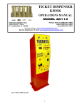
1
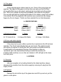
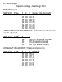
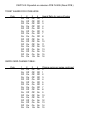
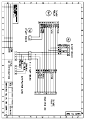
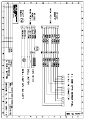
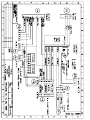
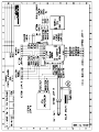
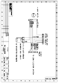
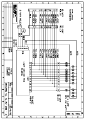
Issued to Production 20th August 1997
BIG WHEEL 1 or 2 player
SERVICE MANUAL
Produced by
Harry Levy Amusement Contractor Ltd
Pysons Road Industrial Estate
Broadstairs, Kent, England CT10 2LF
Tel *843 866464 Fax *843 860144
Distributed in the USA by
Coastal Amusements Inc.
1935 Swarthmore Ave
Lakewood, NJ 08701
Tel 732 905 6662 Fax 732 905 6815
1. INFORMATION.
1.1 This Manual is intended as a guide to the operation, servicing, fault
finding and repairs on the Big Wheel machines. It is important that the
machine operates according to its design criteria.
1.2 All details and specifications shown in this manual are correct at the time
of print. The right to modify equipment, change specifications and instructions
at any time, without notice is reserved as part of Harry Levy Amusement
Contractor Ltd policy of continuous development and improvement.
1.3 Only qualified, professional personnel should gain entry to the machine,
and no liability is accepted by the author or Harry Levy Amusement
Contractor Ltd. for any damage or injury arising from the use of this service
manual.
2. GENERAL SERVICING
2.1 Replacement Parts.
It is of mutual interest that equipment is kept in excellent working condition,
therefore when requested please order original replacement parts from your
distributor or Harry Levy Amusement Contractor Ltd.
2.2 Ticket dispensers.
The ticket dispenser is a Deltronic DL 1275 unit. Please refer to the pink or
yellow manual for ticket machine adjustment and electrical specification.
2.3 . Hopper. (USA)
This is a Coin Controls hopper(s). There are no user serviceable parts.
3. DESCRIPTION OF THE GAME
3.1 Switch on, and Attract mode.
Switch the machine on, the fluorescent lamp will light, the pusher boxes will
move backward and forward, and the wheel will start to rotate. After some
time (depending on the switch settings) the attract mode sounds will operate.
If the volume is not loud enough then adjust the control, which is on the
sound board in the rear of the machine.
The counter will increment each time a coin is inserted. The tilt system &
alarm can be tested by pushing against the machine, the alarm will sound
and any award being made will stop & the remaining award will be lost.
Another alarm test is to stop one of the pusher boxes as if it had jammed, the
alarm will sound. To reset the jam alarm press the reset button which is
located on the top of the machine just behind the top sign, on the left.
3.2 The game
At the selected player station insert a coin. Coins of the wrong type are
rejected. The object of the game is to time the coins entry so that it is fired
into a partly filled cup on the wheel, making it tip its contents onto the pusher
box. This in turn creates the improved possibility of an award for the player.
The cup will right itself as it reaches the bottom of its rotation, ready to be refilled.
Coins which fall off the playfield (USA machine) are counted into the change
hopper by the win hopper. Tickets are then awarded from a ticket dispenser.
4. SPECIFICATIONS
4.1 Dimensions. Height
Width
Depth
1 Player
4.2 Electrical ratings
At 115 Volts 60 Hz :
1 Player
1870mm (73¾”)
645mm (25¼”)
970mm (38¼”)
2.5 Amps /250 Watts
2 Player
1870mm (73¾”)
1265mm (49¾”)
970mm (38¼”)
2 Player
4.0 Amps / 360 Watts
4.3 Errors and alarm signals
If the alarm bell sounds, either a pusher box is jammed or the tilt has been
activated. The tilt will automatically time-out, and reset. The pusher box jam
will require an engineer to rectify the fault, then power the machine back up.
A reset switch is incorporated at the top of the machine to allow an
‘accidental’ jam to be reset without having to switch the machine off.
If tickets (USA machine) run out, then an indicator L.E.D will light on the lower
front entry door.
5. ACCESS
5.1 General.
With the exception of re-Ioading tickets for the ticket machine, always
disconnect the machine from the mains supply by removing it’s plug from the
supply socket.
5.2 Playfield.
Release the lock at the top of the glass door and lift it up and out, put the
glass in a safe place.
5.3 Coin entry.
Coins (or tokens) are guided past an opto sensor and on to the ejector unit.
The coin is automatically ejected onto the playfield area. The ejector is
factory set and should need no adjustment.
5.4 Lower Cabinet.
Each player section has an access door below the playfield which can be fully
removed by releasing the lock at the top of door. A single back door is fitted
which can be fully removed by releasing the two locks at the top of the door.
This gives access to the power supply and the lighting choke board.
5.5 Cash box compartments.
Each player section has an access door below the pay-cup which can be fully
removed by releasing the lock at the top of the door. The cash box may be
fitted with its own lock, for extra security.
5.6 Top sign.
To replace lamps in the topsign, the topsign metalwork must be unscrewed at
the rear and lifted up, taking care to keep the artwork in place. The artwork is
carefully removed from the metalwork, and defective lamps can be replaced.
When replacing the topsign care should be taken to ensure that the artwork
locates in its groove in the wood. Replace all screws in the topsign housing.
5.7 Hoppers.
To access the winnings and change hoppers first remove the front lower
door.
The winnings hopper is below the win chute, the change hopper on the left.
The change hopper pulls forward, the winnings hopper pulls out to the right
when the ticket bin is pulled forward. Hoppers are best returned to your
distributor as they are not intended to be user serviceable.
6. ELECTRICAL SYSTEMS
6.1 General.
In general disconnect the machine from the mains supply then check the
physical condition and operation of the suspect device or unit (remove from
the machine if necessary) and bench test if possible.
In general PCB’s are not user serviceable. Should a problem develop
indicating a board fault it is recommended that the board is returned for repair
or replacement by your distributor, however, fault diagnosis and repair may’
be performed by skilled service personnel but this may invalidate the
warranty. Many of the IC’s are common components and are available from
electronic component suppliers, or from Harry Levy Amusement Contractor
Ltd.
6.2 Wiring check.
If faults occur with any electrical system: - SWITCH THE MACHINE OFF,
then check that:a) All fuses are intact
b) All wires are properly secured to their connector terminals and pins.
c) All connector plugs and sockets are correctly mated.
d) No wires are trapped, damaged or broken.
A visual inspection will reveal the general condition of the wiring. A more
thorough test using a continuity tester will be needed to check apparently
intact wires, however once a machine has been playing successfully, wiring is
very rarely a cause for concern.
6.3 Power supply
The power supply is situated in the lower cabinet compartment beneath the
playfield. When a fault occurs that affects the whole of the machine, the
power supply and regulation system should be checked first.
6.4 Main logic board.
Each player section has its own logic board fitted to the left hand wall in the
rear of the machine. There are fuses for the AC supplies and for each 50V
AC ejector coil.
6.5 Tilt switch. bell and reset switch.
The tilt switch on all versions is situated inside the rear of the cabinet, at the
top left and on each front door. The alarm sounder is located in the topsign.
The tilt alarm reset switch on all versions is fixed inside the topsign with
access to the button from outside the machine.
6.6 Hopper Microphone P.C.B. and reset switch. (USA version only)
Each player section has a microphone P.C.B. and hopper reset switch fitted
to the bulkheads in the lower cabinet compartment. The microphone from
each board is attached to the win chute.
6.7 Sound P.C.B.
The Sound board is in the rear LH side of the machine (1 player viewed from
the back) or on the right of the centre partition wall (2 player).
6.8 Speaker.
All versions of the machine have a speaker fitted to the roof, inside the top
sign. If the speaker is suspected faulty it should be replaced with one of the
same type and rating.
6.9 Lighting.
Fluorescent tubes are situated at the top of the playfield.
Replacement is carried out by releasing the end caps and removing the tube
from the spring clips, inserting a new tube of the correct type and reconnecting
the end caps. Starter replacement may be required occasionally.
Always use exact replacement types.
The light board is situated inside the lower cabinet on the right (1 player) or
on the centre partition wall (2 player).
6.10 Pusher box drive motor and cut-out switch.
All versions of the machine have a drive motor located inside the lower cabinet
compartment under the playfield. A cut-out switch is mounted on the motor support
frame which activates if the pusher boxes become jammed.
6.11 Coin and ticket counters.
On all versions of the machine the coin and ticket counters are located inside
the lower compartment.
6.12 Switch settings.
Dipswitch settings - .Main Logic PCB.
BWHEEL6 V1.0
SWITCH1
Pole
1
2
3
Game Time (Seconds)
Off
On
Off
On
Off
On
Off
On
Off
Off
On
On
Off
Off
On
On
Off
Off
Off
Off
On
On
On
On
3
15
20
25
30
40
50
60
ATTRACT SOUND TRIGGER TIME. Time between attract tunes
can be adjusted.
SWITCH1
Pole
4
5
Off
On
Off
On
Off
Off
On
On
NO ATTRACT SOUND
30 second interval
60 second interval
120 second interval
CONSOLATION AWARDS: Tickets paid on coin in
SWITCH1
Pole
6
7
8
AWARD
Off
On
Off
On
Off
On
Off
On
Off
Off
On
On
Off
Off
On
On
Off
Off
Off
Off
On
On
On
On
0
1
2
3
4
5
6
7
SWITCH 2: Dipswitch on extension PCB FL0295 (Reset PCB.)
TICKET AWARD FOR COINS WON:
Pole
1
Off
On
Off
On
Off
On
Off
On
Off
On
Off
On
Off
On
Off
On
2
Off
Off
On
On
Off
Off
On
On
Off
Off
On
On
Off
Off
On
On
3
Off
Off
Off
Off
On
On
On
On
Off
Off
Off
Off
On
On
On
On
4
Off
Off
Off
Off
Off
Off
Off
Off
On
On
On
On
On
On
On
On
Award Ratio for coins off edge
1
2
3
4
5
6
7
8
9
10
11
12
13
14
15
16
4
Off
Off
Off
Off
Off
Off
Off
Off
On
On
On
On
On
On
On
On
Change coins per swipe card input
0
1
2
3
4
5
6
7
8
9
10
11
12
13
14
15
SWIPE CARD CHANGE TABLE:
Pole
1
Off
On
Off
On
Off
On
Off
On
Off
On
Off
On
Off
On
Off
On
2
Off
Off
On
On
Off
Off
On
On
Off
Off
On
On
Off
Off
On
On
3
Off
Off
Off
Off
On
On
On
On
Off
Off
Off
Off
On
On
On
On
7. MECHANICAL SYSTEMS
7.1 Pusher motor drive.
The motor which drives the pusher boxes is connected to a V belt & pulley
system. The bearings are sealed for life and the belts do not stretch.
If the belt should be damaged, change it by first switching the machine off.
Remove the paycup doors. Unbolt the belt tensioner. The V-belt needs to be
removed, the best way to accomplish this is to place a screwdriver between
the one of the pulleys and the V-belt, then switch the machine on and prise
the V-belt off. Take great care, always be able to turn the machine off
immediately. With the V-belt removed switch the machine off again. Change
the old belt for a new one that is the same specification. Place the new belt
across the pulleys and tighten with the belt tensioner. Now put the V-belt
back on the pulley using the same system. The only other thing that might
need adjusting is the micro switch which is situated at the back of the drive
motor, adjust to suit.
7.2 Pusher boxes.
The pusher boxes run on two Accuride slide bearings. Clean and re-grease
as required. The nylon wheel may wear in time which is noticeable by the
pusher box movement not being smooth. This can be rectified by the
following procedure;a). Switch off the machine at the mains.
b). Open the back of the machine, the nylon wheel can be replaced by
removing the two plates that hold it in place.
c). Replace the nylon wheel with a new one. Grease the wheel and
reassemble.
7.3 Coin entry chutes.
These can be changed or replaced. Care should be used when replacing
them to ensure they locate in the firing mechanism correctly.
7.4 The Wheel.
The cup “tip” can be adjusted by carefully bending the stops underneath.
This will allow more or less coins to tip the cup.
8. TROUBLE-SHOOTING
The following is a guide to some faults and remedies. Always replace faulty
items with units of the same specification. Determine the cause of the fault
and rectify to avoid recurrence of a problem. Test a coin mech. or ticket
dispenser by fitting a known good unit from another machine in place of the
suspect unit. The ticket machines are quite easy to fault find and repair on
site.
SYMPTOM
No sound
POSSIBLE FAULT
Volume / Speaker
REMEDY
Adjust volume / Check
speaker
Sound board
Replace if faulty
Lights out
Tube, Starter, Choke
Check each item.
Replace if faulty.
Ticket machine
not working
Ticket motor / PCB
Bench test. Check
transistor 2N2222,
IC40106, opto sensor
Replace logic PCB
Check switches
Logic / Inhibit switch
Pusher not moving
Jam micro switch
Check that micro switch
works.
Machine not paying out
Counter hopper
Payout hopper
Change hopper
Refill hopper
Change hopper
Tilt alarm not working
Coin counter not working
Ticket counter not working
Tilt PCB
Counter / Opto sensor
Check counter
Change board
Test / change for new one
Change for new one
Check ticket opto
Change ticket machine
Coin Launch System -set-up & adjustment.
The coin launch system has been factory adjusted for optimum performance
with your specified coin.
The system incorporates an automatic voltage compensation circuit, that
adjusts the supply voltage to the solenoid coil to compensate for the variation
in performance that occurs when the system warms up in normal use.
This ensures the players always have a game with similar characteristics, .
from the first coin of the day through to the last coin.
ADJUSTMENT
Should the need arise to adjust the coin launch units please follow this
procedure ;Note;- The coin should be launched to hit the ‘BIG WHEEL’ about 90mm
from the top, which is half way between the top of the wheel and the centre
cone.
1. Test the performance of the system.
2.
If necessary, adjust the finger controls on the control board. Each coin
launcher has its own control.
The control board is located under the launch units, on the right hand
side.
3.
If there is insufficient adjustment on that control, a mechanical adjustment
of the firing solenoid will be needed. Set the control board control to the midway
position.
1) On the rear of the solenoid are four fixing bolts, loosen the bolts to
allow the solenoid coil to move up and down. Note;- only small adjustments
of 1 or 2mm are likely to be required.
2) Adjust the coil upwards to get more power, and throw the coin
harder.
3) Adjust the coil downwards to reduce the power, reducing the throw
of the coin.
4) Once the mechanical adjustment is about right, fine tune the coin
throw with the control board finger control.