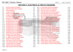
1
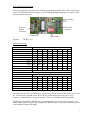
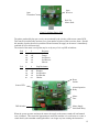
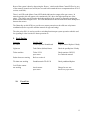
UK
Spiral Vend Feature
Produced by
Harry Levy Amusement Contractor Ltd
Unit 6 Patricia Way
Pysons Road Industrial Estate
Broadstairs
Kent
CT10 2LF
England
Tel: +44 1843 866464 Fax: +44 1843 860144
Email: [email protected]
CONTENTS
Section 1
Information
Section 2
2.1
2.2
General service
Replacement parts
Ticket dispensers
Section 3
3.1
3.2
3.3
3.4
Receiving your machine
Switch on
Tilt
Preparing the machine
Normal play
Section 4
4.1
4.2
4.3
4.4
4.5
4.6
Access
General
Playfield
Coin entry compartment
Lower cabinet
Cashbox compartments
Top sign
Section 5
5.1
5.2
5.3
5.4
5.5
5.6
5.7
5.8
5.9
5.10
Electrical systems
General
Wiring check
Power supply, main component board
Flashing Light Supply
Tilt switch, bell and reset switch
Sound and Motor PCBs
Speaker
Lighting
Counters
Vend Spiral Feature
Section 6
6.1
6.2
6.3
Switch settings
Tilt & Diverter PCB
Sound PCB
Changer PCB (if fitted)
Section 7
7.1
7.2
7.3
7.4
7.5
Mechanical systems
Pusher motor
Pushers
Coin entry chutes
Diverter
Vend Spiral Feature
Section 8
Motor Control
Section 9
Fault finding
Section 10
Parts List
2
1.
Information
This Manual is intended as a guide to servicing, fault-finding and repairs on Lets Twist Again
machines.
All details and specifications shown in this manual are deemed correct at the time of print. The right
to modify equipment, change specifications and instructions at any time, without notice is reserved
as part of Harry Levy Amusement Contractors Ltd policy of continuous development and
improvement.
Only qualified, professional personnel should gain entry to the machine, and no liability is accepted
by the author or Harry Levy Amusement Contractor Ltd. for any damage or injury arising from the
use of this service manual.
It is important that the machine operates according to its design criteria. A detailed description of
the sequence of events that take place when the machine is working properly are set out in this
manual.
2.
General Service
2.1 Replacement Parts.
It is of mutual interest that equipment is kept in excellent working condition, therefore when
requested please order original replacement parts from your distributor or Harry Levy Amusement
Contractor Ltd. A parts list is included in Section 10.
2.2 Ticket dispensers.
The ticket dispenser (when fitted) is a Deltronic DL 1275 unit. Please refer to the Deltronic manual
for ticket machine adjustment and electrical specification.
3.
Receiving your machine
Remove any transit packing material, then site your machine on a smooth level floor. Please handle
your machine with care using appropriate lifting equipment: do not drop it or subject it to shocks or
a damp environment. Connect the machine (top feed only) to the mains using the lead supplied.
This is fitted with a moulded plug (UK), with a suitable fuse already installed. There is only top feed
facility fitted to this game.
3.1 Switch On.
The mains switch is in section 1. This is directly above one of the two locked cashbox doors.
Switch the machine on, all the fluorescent lamps will light and the pusher boxes will move
backwards and forwards. At intervals the attract sounds will operate. The volume control is located
on the sound board inside section 2, (to the right of section 1) on the left-hand wall.
When a coin is inserted, there is a 'coin in' sound; the coin counter increments; the diverter
solenoid energizes and opens the diverter flap, allowing any coins that are pushed off the playfield
to fall into the pay cup.
3.2 Tilt.
There are tilt sensors on each pay cup door and in the top sign. Banging the lower doors or shaking
the top sign will sound the alarm bell (screamer), switch off the playfield lights, and de-energize all
the diverters, so that all coins shaken loose from the playfields are routed to the cash-boxes. This
3
state will continue for approximately 5 seconds, then the machine reverts to its normal play mode,
unless the tilt state continues.
3.3 Preparing the Machine.
To Float or Prime each playfield requires approximately 500 coins, of which the first 400 may be
hand placed in small batches onto the moving pusher box. The final 100, plus coins from the pay
cup, should be played into the machine through the coin entries. Add more coins if required, (don’t
forget: a few coins will probably end up in the cash boxes).
This ensures the playfield looks its best and immediately attracts the players, ensuring rapid high
profits. Take the initial counter readings at this time.
3.4 Normal Play
When a player inserts a coin it passes a sensor that switches only that section on, energizing the
diverter, which allows coins pushed from the playfield to be routed to the pay cup. Sections in play
remain enabled for approximately 20 seconds after the last coin is inserted to allow the player full
benefit from the effects of his coins. There is a coin counter behind each coin entry door that
records every coin inserted.
The count is also recorded by the Feature PCB. When sufficient coins have been entered, an award
is made from the spiral prize rail, and a fanfare sounds. The prize counter increments.
If tilted whilst being played the tilt system takes over the entire machine, switching off all diverters
and the playfield lights. The alarm is sounded. After 5-10 seconds, the alarm stops and the lights
come back on, unless the tilt condition is still present. A coin must be inserted to re-open a diverter.
4. ACCESS.
4.1 General
Always disconnect the machine from the mains supply before opening the machine.
DON'T TAKE CHANCES !
4.2 Playfield.
Release the lock at the top of the glass door and lift it up and out, place the glass somewhere safe.
4.3 Coin entry compartment.
Each player station has a coin entry door to provide access to the internal compartment. Release the
lock at the top and remove the door.
4.4 Lower Cabinet.
Each player station has an access door below the playfield, which can be fully removed by releasing
the locks at the top of the door.
4.5 Cash box compartments.
The machine has one large wooden cash box in the base of the machine, with 4 individual metal bins
inside. These are accessible from section 1 only. Section 3 can also be opened for access. Release
the locks and remove the doors.
4.6 Topsign.
To gain entry to the topsign, pull out one of the Perspex panels by exerting force half way between
the waist and the top on both sides of the panel. It will bow outwards and snap to the fully bowedout position. Push the lower edge up from its lower slot to remove completely.
4
5.
Electrical Systems
5.1 General.
When a problem arises, disconnect the machine from the mains supply then check the physical
condition and operation of the suspect device or unit. Remove from the machine if necessary and
bench test if possible.
In general P.C.B.'s are not user serviceable. Should a problem develop indicating a board fault it is
recommended that the board is returned for repair or replacement by your distributor or Harry Levy
Amusement Contractor. Fault diagnosis and repair may be performed by skilled service personnel,
but this may invalidate the warranty.
5.2 Wiring check.
If faults occur with any electrical system: SWITCH THE MACHINE OFF: then check that:a) There is a suitable mains supply.
b) All fuses are intact.
c) All plugs and sockets are correctly mated.
d) No wires are trapped, damaged or broken.
e) All wires are properly secured to their terminals and pins.
A visual inspection will reveal the general condition of the wiring. A more thorough test using a
continuity tester will be needed to check apparently intact wires, however once a machine has been
playing successfully for some time wiring is very rarely a cause for concern.
5.3 Power Supply Main component board.
The power supply board with transformer and associated components is located in the base of the
machine in section 1. When faults occur that affect the whole of the machine, the power supply and
regulation system should be investigated first.
WARNING - High Voltages exist in this machine, DISCONNECT FROM THE MAINS
SUPPLY.
Check the fuses. Refer to schematics and drawings to check wiring connections.
Check the following supplies: Diverter solenoids (when activated) - 50 Volts A.C.
The supply to the sound board: - 24 Volts D.C.
The supplies to the Tilt & Diverter Board: - 12vA.C. & 9v A.C.
The supply to the Feature PCB: - 12-14v D.C.
5.4 Flashing Light supply
The main flashing light supply is fitted inside the coin entry unit in the centre, along with the
flashing light PCB.
Fuses are provided for each supply, and also for the mains supply.
5.5 Tilt switch, bell and reset switch.
The pendulum tilt switch and alarm bell are situated inside the top sign.
The motor jam reset switch is fitted to the base of the machine in section 2, left-hand side, accessible
from outside the machine just under the corner of the pay cup door.
5.6 Sound PCB and Motor PCB.
The sound PCB is located in section 2 on the left hand wall. The volume control is a spindle on the
edge of the board.
The motor control PCB is in section 2 on the right hand wall. See section 8 for details.
5
These PCBs are not intended to be user-serviceable; we recommend they are sent to your distributor
for repair should the need arise.
5.7 Speaker.
The speaker is fitted to the floor inside the topsign. If the speaker is suspected faulty it should be
replaced with one of the same type and rating, 8 ohms 15 Watts.
5.8 Lighting.
Fluorescent tubes are situated :-.
a) Inside the top sign.
b) Inside the metal playfield legs.
Replacement is carried out with the machine switched OFF, then releasing the end caps and
removing the tube from the spring clips, inserting a new tube of the correct type and re-connecting
the end caps.
The board for the chokes and starters, which controls the playfield leg fluorescent tubes is situated
behind the pin perspex playfield compartment fixed in the middle of the machine.
The top sign houses its own light boards.
Starter replacement may be required occasionally. Always use exact replacement types.
5.9 Counters
Counters are located inside each coin entry door. The Coin-in counter is on the left, the Prize
counter on the right. Take readings each time the cash box is emptied.
6
5.10 Vend Spiral Feature PCB
This board controls the operation of the vending spiral and the operation of the LEDs on the feature
board. The LED feature board is merely an arc of LEDs protruding through the pin perspex to add
attraction and player appeal.
Supply Healthy
LED
Power &
Feature
Connector
LED Feature
Connectors
Program IC
Program:
DIP Switches
TWIST7 V1.0
DIP Switch settings:
Item Description
Poles
Win Odds:
(test setting) 20:1
50:1
100:1
150:1
200:1
250:1
300:1
350:1
1
2
3
off
on
off
on
off
on
off
on
off
off
on
on
off
off
on
on
off
off
off
off
on
on
on
on
4
5
6
7
8
Cont’…
Cont’…
Item Description
Poles
1
2
3
4
5
6
off
on
off
on
off
off
on
on
7
8
No. Of Spiral Turns:
1
2
3
4
The odds above do NOT mean that a prize is given every time the coin-in count reaches 20, 50, 100
etc. A prize may be awarded at any time, but over a period of days and weeks, the average
frequency of award will be as set by the switches. This is in accordance with UK legislation.
The Number of spiral turns should be set to accommodate the size of your prize. If the prize is too
bulky to hang from every spiral ring, hang them on alternate rings, or every third or fourth ring, and
set the number of turns accordingly.
7
6.
Switch Settings
SEE SECTION 5.10 FOR SPIRAL VEND BOARD SWITCH SETTINGS.
SEE SECTION 8 FOR MOTOR CONTROL BOARD SWITCH SETTINGS.
6.1
Tilt Diverter Board
The control PCB for the tilt and diverter functions is located behind the central Perspex and is best
accessed from station 1.
There is a single bank of 8 dip switches on board:
6.2
POLE
1
OFF
ON
OFF
ON
OFF
ON
OFF
ON
POLE
4
OFF
ON
POLE
5
OFF
ON
OFF
ON
POLE
8
OFF
ON
2
OFF
OFF
ON
ON
OFF
OFF
ON
ON
3
Game Time
OFF 3 Seconds (test only)
OFF 20seconds (default)
OFF 30 Seconds
OFF 40 Seconds
ON
50 Seconds
ON
60 Seconds
ON
75 Seconds
ON
90 Seconds
No tilt condition at power up
Tilt condition at power up
6
OFF
OFF
ON
ON
Tilt time
5 Seconds
10 Seconds
15 Seconds
20 Seconds
Each coin counter separate
All coin counters to channel 1 counter
Sound board
POLE
1
OFF
ON
OFF
ON
OFF
ON
OFF
ON
2
OFF
OFF
ON
ON
OFF
OFF
ON
ON
3
OFF
OFF
OFF
OFF
ON
ON
ON
ON
No attract music or change message
30 second attract music interval
60 second attract music interval
90
120
150
180
210
8
POLE
POLE
POLE
4
OFF
ON
Attract changer message disabled
Attract changer message enabled
5
OFF
ON
OFF
ON
6
OFF
OFF
ON
ON
Attract music disabled
Attract music minimum volume
Attract music medium volume
Attract music maximum volume
7
OFF
ON
OFF
ON
8
OFF
OFF
ON
ON
Coin in sound disabled
Coin in sound minimum volume
Coin in sound medium volume
Coin in sound maximum volume
The following are always played at the maximum level:Win fanfare
This machine also gives change
Please call the attendant
6.3
Changer settings – UK only (when fitted)
Payout Settings ;The following diagram shows the changer board set to give change in 10p coins, accepting only the
higher value £1, 50p and 20p coins.
If the coin mech is capable of accepting the smaller coins, and the board is set to accept them, the
board will totalize the value and give change when the value reaches the rotary switch setting.
A slowly flashing 'Change available' light indicates a part credit.
Connector
FL 0001
Changer Board
4
ON
5
6
3
7
2
1
2 3 4
Dipswitch
5 6
8
1
0
9
Rotary Switch
9
Inhibit / Accept 6 Pole Dipswitch ;Pole 1
Coin 1
Pole 2
Coin 2
Pole 3
Coin 3
Pole 4
Coin 4
Pole 5
Coins 5 & 6
Pole 6
Coins 7 & 8
Rotary Switch Position.
0
1
2
3
4
5
6
Note,
7
ON = Accept coin, OFF = Inhibit coin
8
9
Payout Coin
Inhibit ALL
1p
2p
5p
10p
20p
50p
£1
Not used
Not used
Program
Ref.
Coin
1
Coin
2
Coin
3
Coin
4
Coin
5
Coin
6
Coin
7
Coin
8
Change1 V1.0
£1
50p
20p
10p
2p
---
---
---
Change2 V1.0
£1
50p
20p
10p
10p
5p
5p
2p
Change5 V1.0
£1
50p
20p
1p
10p
---
5p
2p
Change7 V1.0
£1
50p
20p
10p
2p
5p
5p
2p
7.
HL
Part No.
6902
Mechanical Systems
7.1 Pusher motor
The central pusher motor is a Parvalux unit and needs no maintenance.
The motor-jam & reset system is explained in detail in section 8.
The motor-jam reset button is located in section two, to the bottom left of the lower pay-cup door on
the under side near the corner leg.
When the system detects a jam the motor will be shut off. The cause of the jamming should be
cleared manually, and the reset button pushed to restart the motor. (Alternatively, switch the game
off, then on again).
7.2 Pusher boxes.
The drive to the pusher boxes is via a crank and 6 link arms.
The pusher boxes are each mounted on two Accuride bearings, which move backwards and forwards
due to the crank action. These bearings are reliable but will attract dust, which will stick to the
grease and accelerate wear. Inspect annually. Clean and re-grease as necessary.
7.3 Coin entry Chutes.
Coin entry chutes are situated on the front of the machine. The chutes are fixed and require no
maintenance.
7.4 Diverters.
Coin diverters are located in each lower cabinet beneath the win chute. Diverters are reliable, but if
something appears wrong first check for mechanical jams (a coin stuck), then check the fuses (in
line) and power to the solenoid. If the solenoid has failed replace it with an equivalent unit.
10
Ensure the solenoid travel is not restricted. The plunger must seat properly for the magnetic field to
work properly. Otherwise the unit will overheat.
If the diverter has to be removed then take the following steps;
1. Unlock and remove the pay cup door.
2. Disconnect the solenoid loom.
3. Unbolt the diverter from the woodwork at the rear by removing the four M5 retaining
bolts
4. The diverter can now be removed, and repairs carried out
7.5 Vend Spiral Feature
The vend spiral is connected to the output shaft of a 24 V DC geared motor. This in turn is mounted
on a bracket that is fitted to the rear of the pin perspex. A microswitch is also fitted to this bracket,
with the actuating arm sensing a flat on the shaft. This microswitch provides the feature interface
board with confirmation that the motor is operating when demanded by the control logic. The
feature interface board controls the operation of the motor.
8.
Pusher Box Motor Control
This system utilises an opto-electronic method to monitor the motor load, and stop the motor in the
event of a restriction or jam.
The motor drive shaft extends some 35mm out of the rear end of the motor case. It is here that the
opto sensor PCB is located, secured to the motor case. The motor shaft has a hole drilled in it,
through which the infrared beam may pass when correctly aligned. With the rotation of the motor
shaft, this results in the beam being continually interrupted, and a resultant string of pulses produced
by the opto receiver.
Rear End Of
Motor Case
Opto Sensor
PCB
Motor Shaft
Opto Sensor PCB Mounted To Motor
11
Opto
Receiver
Opto
Transmitter
Hole For
Motor Shaft
Close Up Of Opto Sensor PCB
The pulses produced by the opto receiver are monitored by the circuitry of the motor control PCB.
This control circuit basically monitors for a given number of pulses within a set time frame. Should
this number of pulses decrease beyond the tolerated amount, the supply to the motor is immediately
switched off via a solid-state relay.
The control of the motor cut off point may be set by way of a 4 way DIP switch thus:
Pole
Pole
1
2
Response
off
on
off
on
off
off
on
on
Fastest
2nd Fastest
2nd Slowest
Slowest
3
4
Stop Resistance
off
on
off
on
off
off
on
on
Weakest
2nd Weakest
2nd Hardest
Hardest
Reset
Switch
Sensor LED
Alarm/Operation
Relay
Motor
Fuse
DIP Switches
Motor Supply
Solid State Relay
When the system operates and stops the motor, the supply to the motor remains off until manual
reset is initiated. This creates the opportunity to ensure the machine is in a safe state to re-start; a
visual check by the attendant ensuring that there is no longer any item causing the obstruction.
12
Reset of the system is done by depressing the 'Restart' switch on the Motor Control PCB or by way
of the remotely located reset switch (in a recessed hole beneath the lower compartment door of No.2
section, on the left).
There is an LED on the Motor Control PCB which indicates the output of the opto-sensor. In
normal operation this will appear to be continuously ON, due to the high repetition rate of the
pulses. This facility may be used to check the operation of the sensors, by manually rotating the
motor shaft and observing the LED. The LED should turn on then off as the hole in the shaft passes
between the sensors.
The 20mm fuse on this PCB is to provide over current protection to the solid state relay/motor
combination (Refer to specific machine manuals for type and rating).
The other relay (RL1) is used to provide a switching function upon system operation which is used
for signalling to other circuits for alarm operation etc.
9. Fault finding
Symptom
No sound
Possible Fault
Volume/Speaker/Sound board
Remedy
Adjust volume/Replace if faulty
Lights out
Tube/Choke (ballast)/Starter
Check the part/Replace if faulty
Ticket machine
Ticket P.C.B
opto sensor
Check transistor 2N2222,
See Deltronic manual.
Pusher boxes not moving
Refer to section 8.
Tilt alarm not working
Pendulum stuck/Tilt P.C.B
Check pendulum/Replace
check counter
opto sensor
Change for new one.
check every opto sensor.
Coin/Ticket counter
not working
10.
Parts List
13