1
Test Run
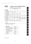
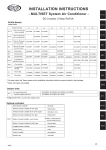
3. Main Outdoor Unit PCB Setting
z Examples of the No. of indoor units settings (S005, S004)
No. of indoor units
Indoor unit setting (S005)
(3P DIP switch, blue)
10 20 30
1 unit (factory setting)
All OFF
ON
ON
1
2
3
2
3
2
3
2
3
OFF
2
3
OFF
Set to 1
OFF
ON
ON
Set to 1
OFF
ON
ON
1
Set to 1
3 ON
1
ON
ON
40 units
1
2 ON
1
31 units
Set to 1
1
1 ON
1
21 units
1
OFF
ON
ON
11 units
Indoor unit setting (S004)
(Rotary switch, red)
0
1 & 3 ON
1
Set to 0
z Examples of refrigerant circuit (R.C.) address settings (required when link wiring is used) (S003, S002)
System address No.
System 1 (factory setting)
System address (S003)
(2P DIP switch, blue)
10 20
ON
ON
1 2
ON
OFF
ON
1
Both OFF
1
1 ON
System 11
1
System 21
System 30
System address (S002)
(Rotary switch, black)
2
ON
OFF
ON
1 2
ON
OFF
ON
2
OFF
Set to 1
1
Set to 1
1
Set to 1
2 ON
0
1 & 2 ON
1
Set to 0
2
z Examples of the No. of outdoor units settings (S006)
No. of outdoor units
Outdoor unit setting (S006)
(3P DIP switch, blue)
1 unit (factory setting)
1 ON
ON
ON
1
2
3
OFF
ON
2
3
OFF
ON
2
3
OFF
ON
2 units
2 ON
1
ON
3 units
3
1 & 2 ON
1
4
z Address setting of main outdoor unit (S007)
Unit No. setting
Address setting of outdoor unit (S007)
(3P DIP switch, blue)
ON
ON
Unit No. 1 (main unit)
(factory setting)
1
2
3
5
OFF
z Address setting of sub outdoor unit
Unit No. setting
Unit No. 2 (sub unit)
(factory setting)
Address setting of outdoor unit (S007)
(3P DIP switch, blue)
ON
ON
1
2
3
OFF
ON
ON
Unit No. 3 (sub unit)
6
2 ON
1 & 2 ON
1
2
3
OFF
The sub unit control PCB contains the same switches as the main unit control PCB for No. of indoor units, No. of outdoor units,
and system address. However it is not necessary to set these switches.
5-5
7
8