1
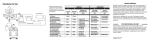
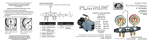
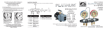
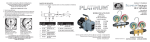
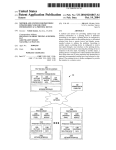
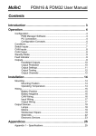
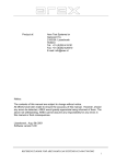
LIMITED WARRANTY Directions For Use EVAPORATOR D CONDENSER B A C E COMPRESSOR RECEIVER Caution: Always consult MANIFOLD equipment manufacturer's service manual or instrucA B C Charging and tion sheet for recommended procedures. Low Side High Side Evacuation Port Blue Red Yellow To Observe Closed Closed Operating Pressures To Charge Refrigerant Open Closed Connect Line Through Suction Valve to Refrigerant Supply To Charge Oil Open Closed Connect Line Through Suction Valve To Oil Supply To Charge Liquid Refrigerant Closed Open Connect Line Through Discharge Valve To Refrigerant To Build Low Pressure; Open Open Refrigerant For Control Setting Line Closed Or Leak Detecting To Purge Refrigerant Closed Open Refrigerant From Discharge Valve Line Open To Evacuate With Open Open Connect To Auxiliary Vacuum Pump Vacuum Pump COMPRESSOR D E Discharge Suction Service Valve Service Valve Red Blue Back Seated & Cracked Open Back Seated & Cracked Open Back Seated Back Seated & Cracked Open Front Seated Front Seated FOR PROFESSIONAL USE ONLY Midway Open Back Seated & Cracked Open Back Seated & Cracked Open Midway Open Manifold bar has a lifetime warranty, while the components, i.e. gauges, hoses, handles, hose holders, etc. are covered under the limited warranty policy. Products are warranted for a period of one year from date of shipment by JB and limited to repair, replacement or credit, if in our opinion are defective due to workmanship and/or materials. Defective components should be returned to the wholesaler from which the product was purchased for evaluation. Manifolds are designed for use with all refrigerants except ammonia (R-717). Working pressures are limited to gauge dial range. Use of this manifold under any other conditions voids the warranty. Midway Open JB manifolds are designed for use by technically trained AC/R service engineers only. Due to the high pressures encountered in all systems that this manifold will be used on, plus the dangers due to the physical and chemical nature of refrigerants and oils present in all systems, misapplication could result in injury or death. Midway Open FORM NO. 23000-308 PRINTED IN U.S.A. Each gauge is individually tested and calibrated prior to shipment. Due to its sensitivity, the gauge may need to be "zeroed in" prior to usage. Adjusting Gauge Recal to Zero 1. Remove lens. 2. Turn recal screw slightly in the opposite direction that pointer is to be moved. Maximum recal screw adjustment is 1/2 turn. Over adjustment will permanently destroy calibration. 3. Replace lens. CHARGING AND TESTING REPAIR PARTS See your wholesaler for a complete line of gauges 9 DEEP VACUUM PUMPS 1 7 8 3 4 5 6 2 NO. REF. PART NO. Turn recal screw counterclockwise. Pointer turns clockwise. Turn recal screw clockwise. Pointer turns counter-clockwise. Gauges are sensitive instruments. Over adjustment and/or being subjected to pressures over dial range are not covered under warranty terms. 2-Valve Brass/Aluminum Manifold TM TM DESCRIPTION 1 MR-601 Handwheel & Screw 2 U1-4A 1/4" Intake 3 MR-520 Sight Glass 4 MR-505 Piston w/Seat & O-Rings 5 MR-606 Stem & Nut NO. REF. PART NO. DESCRIPTION 6 MR-601 Handwheel & Screw 7 MR-503 Handwheel Screws (2) 8 MR-509 O-Ring (2) 9 M2-102N Hanging Hook With Free Floating, Double O-Ring , Piston Seal , Featuring Heavy Duty, High Performance 1/2 HP, 60 Cyc Motor DV-42N DV-85N DV-142N DV-200N DV-285N 1.5 CFM 3 CFM 5 CFM 7 CFM 10 CFM Also Available With Dual Voltage Motors Technical service: 800-323-0811 E-Mail: [email protected] Web Site: www.jbind.com 2006 JB Industries Inc. LIMITED WARRANTY INSTRUCTIONS PARTS LIST