1
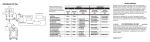
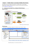
TouchPAD TPD/VPD Series HMI Device User Manual Version 1.1.0, Jul. 2015 WARRANTY All products manufactured by ICP DAS are warranted against defective materials for a period of one year from the date of delivery to the original purchaser. WARNING ICP DAS assumes no liability for damages consequent to the use of this product. ICP DAS reserves the right to change this manual at any time without notice. The information furnished by ICP DAS is believed to be accurate and reliable. However, no responsibility is assumed by ICP DAS for its use, nor for any infringements of patents or other rights of third parties resulting from its use. COPYRIGHT Copyright © 2015 by ICP DAS. All rights are reserved. TRADEMARKS Names are used for identification purposes only and may be registered trademarks of their respective companies. CONTACT US If you have any questions, please feel free to contact us via email at: [email protected], [email protected] TPD/VPD Series HMI Device User Manual TABLE OF CONTENTS PREFACE ....................................................................................................................................................................... 4 1. INTRODUCTION ........................................................................................................................................................ 5 1.1 FEATURES .............................................................................................................................................................. 6 1.2 MODULE NAMING CONVENTION ............................................................................................................................... 7 1.3 SELECTION GUIDE ................................................................................................................................................... 8 1.3.1 TPD Series Models ......................................................................................................................................... 8 1.3.2 VPD Series Models......................................................................................................................................... 9 1.4 SPECIFICATIONS .................................................................................................................................................... 10 1.4.1 TPD-280/280U/283/283U Series Models .................................................................................................... 10 1.4.2 TPD-280-H/280-Mx/283-H/283-Mx/283U-H/283U-Mx Series Models....................................................... 11 1.4.3 TPD-430/430-EU/433/433-EU Series Models.............................................................................................. 12 1.4.4 TPD-432F/433F Series Models..................................................................................................................... 13 1.4.5 TPD-703/703-64 Series Models ................................................................................................................... 14 1.4.6 VPD-130/130N/132/132N/133/133N Series Models .................................................................................. 15 1.4.7 VPD-142/142N/143/143N Series Models ................................................................................................... 16 2. HARDWARE INFORMATION......................................................................................................................................17 2.1 APPEARANCE ....................................................................................................................................................... 17 2.1.1 TPD-280/283 Series Models ........................................................................................................................ 17 2.1.2 TPD-280-Mx/283-Mx/283U-Mx Series Models ........................................................................................... 19 2.1.3 TPD-430/433 Series Models ........................................................................................................................ 21 2.1.4 TPD-432F/433F Series Models..................................................................................................................... 23 2.1.5 TPD-703/703-64 Series Models ................................................................................................................... 25 2.1.6 VPD-130/130N Series Models ..................................................................................................................... 27 2.1.7 VPD-132/132N/133/133N Series Models ................................................................................................... 28 2.1.8 VPD-142/142N/143/143N Series Models ................................................................................................... 30 2.2 PIN ASSIGNMENTS ................................................................................................................................................ 32 2.2.1 TPD-280/283/430/433 Series Models ......................................................................................................... 32 2.2.2 TPD-432F/433F Series Models..................................................................................................................... 33 2.2.3 TPD-703/703-64 Series Models ................................................................................................................... 34 2.2.4 VPD-130/130N Series Models ..................................................................................................................... 35 2.2.5 VPD-132/133 Series Models ........................................................................................................................ 36 2.2.6 VPD-142/143 Series Models ........................................................................................................................ 37 2.3 DIMENSIONS........................................................................................................................................................ 38 Copyright © 2015 ICP DAS Co., Ltd. All Rights Reserved. Page: 2 TPD/VPD Series HMI Device User Manual 2.3.1 TPD-280/283 Series Models ........................................................................................................................ 38 2.3.2 TPD-430/432/433/703 Series Models ......................................................................................................... 40 2.3.3 VPD-130/132/133 Series Models ................................................................................................................ 42 2.3.4 VPD-142/143 Series Models ........................................................................................................................ 43 2.4 MOUNTING THE HARDWARE ................................................................................................................................... 44 2.4.1 Wall Mounting ............................................................................................................................................ 44 2.4.2 XV-boards Assembly on the VPD Series Models .......................................................................................... 47 3. GETTING STARTED ....................................................................................................................................................49 3.1 OBTAINING/INSTALLING THE HMIWORKS SOFTWARE .................................................................................................. 49 3.2 CREATE A NEW PROJECT IN THE HMIWORKS ............................................................................................................. 50 3.3 SUPPLY POWER TO THE TOUCHPAD .................................................................................................................................. 53 3.3.1 DC Power Supply ......................................................................................................................................... 53 3.3.2 PoE Power Supply ........................................................................................................................................ 54 3.4 DOWNLOADING METHODS FOR TOUCHPAD .............................................................................................................. 55 3.4.1 Setup RS-485-downloaded Devices ............................................................................................................. 55 3.4.1.1 Applications are downloaded through RS-485 .................................................................................................... 55 3.4.1.2 What to do if the download process hangs?....................................................................................................... 60 3.4.2 Setup Ethernet-downloaded Devices .......................................................................................................... 61 3.4.2.1 Applications are downloaded through Ethernet ................................................................................................. 61 3.4.2.2 What to do if the download process hangs?....................................................................................................... 68 3.4.3 Setup USB-downloaded Devices .................................................................................................................. 69 3.4.3.1 Applications are downloaded through USB Port ................................................................................................. 69 3.4.3.2 Updating MiniOS through USB Port .................................................................................................................... 73 3.4.3.3 What to do if the download process hangs?....................................................................................................... 77 4. CALIBRATIONS .........................................................................................................................................................78 5. CONNECTING TO I/O DEVICES ..................................................................................................................................80 5.1 ACCESS A MODBUS TCP SLAVE DEVICE ..................................................................................................................... 80 5.2 ACCESS A MODBUS RTU SLAVE DEVICE .................................................................................................................... 84 5.3 CONNECTING TO I/O EXPANSION BOARDS (XV-BOARD) ............................................................................................... 88 Copyright © 2015 ICP DAS Co., Ltd. All Rights Reserved. Page: 3 TPD/VPD Series HMI Device User Manual Preface Thank you for buying TPD/VPD Series HMI Devices, TouchPADs, which are made by ICP DAS Co., Ltd. We suggest you read through this user manual before you set up these devices and develop their programs. SUPPORT This manual relates to the following modules: TPD-280, TPD-280U, TDP-283, TPD-283U, TPD-820-H, TPD-283-H, TPD-283U-H, TPD-280-Mx, TPD-283-Mx, TPD-283U-Mx, TPD-430, TPD-430-EU, TPD-433, TPD-433-EU, TPD-432F, TPD-433F, TPD-703, TPD-703-64, VPD-130, VPD-130N, VPD-132, VPD-132N, VPD-133, VPD-133N, VPD-142, VPD-142N, VPD-143, VPD-143N PURPOSE This manual shows how to use TouchPADs and develop programs. This manual mainly contains the following parts: Introduction: basic understandings of TouchPADs. Hardware: specifications, dimensions, and installations. Software: mainly how to build a project and HMIWorks introductions. PERSONNEL This manual is fit for following personnel: End Users Engineers Technicians Copyright © 2015 ICP DAS Co., Ltd. All Rights Reserved. Page: 4 TPD/VPD Series HMI Device User Manual 1. Introduction Our solution for HMI (Human Machine Interface) is composed of GUI (Graphical User Interface) based touch screens and an integrated software development package. ICP DAS hears the voices of our customers and is dedicated to providing a series of solutions particularly for intelligent building, equipment monitoring, factory automation and automatic controls. Its development software, HMIWorks, provides plenty of widgets and a variety of templates. Combined with the high resolution color touch screen of the TouchPAD series, a GUI can be realized with your own unique fashion and style. Development is no longer difficult and project accomplishment is within reach. ICP DAS provides two types of touch HMI devices, the TPD series and the VPD series. The TPD series is designed for home/building automation applications and the VPD series is designed for factory/machine automation applications. Both have many common features, such as a high-resolution touch screen, RTC, and a variety of communication interfaces, including RS-232/RS-485, Ethernet, USB. However, each still has its own specific features for its respective target applications. For the TPD series, you can use an external wall box to help you smoothly blend the TPD series device into your decoration. For the VPD series, the rubber keypad, IP-65 waterproof front panel and DIN-Rail/panel mounting are designed for harsh environment, and are especially suitable for factories. Copyright © 2015 ICP DAS Co., Ltd. All Rights Reserved. Page: 5 TPD/VPD Series HMI Device User Manual 1.1 Features Excellent C/P ratio (cost/performance) High-Color high-resolution resolution touch screen PoE, Power over Ethernet (PoE) RS-485 network (including SelfTuner)/RS-232 (3 pins) RTC (Real Time Clock) Buzzer Rubber Keypad (Option for VPD Series) Graphical user interface designer Free development tool: HMIWorks Support the C language and Ladder Designer Support user-defined third party protocol (C language) Modbus Protocol enables remote control of I/O modules and integration with SCADA software ESD Protection: 4 kV Waterproofed Front Panel (VPD: IP65, TPD: IP40) Operating temperature: -20 ~ 50 oC (2.8” TPD: -20 ~ 70 oC) Copyright © 2015 ICP DAS Co., Ltd. All Rights Reserved. Page: 6 TPD/VPD Series HMI Device User Manual 1.2 Module Naming Convention There are many different products available, and sometimes it is difficult to remember the specifications for any given product. However, if you take a few minutes to understand the module naming conventions, it may save your time and prevent confusion. The figure below shows how the module naming conventions work for each TPD/VPD series product. Touch Screen Size Communication Interface Special 28: 2.8 inch For 2.8 inch: For 4.3 inch: For 7.0 inch: 43: 4.3 inch 0: RS-485 0: RS-485 3: Ethernet 70: 7.0 inch 0U: RS-485 + RTC 2: RS-485 x 2 3: Ethernet 3: RS-485/RS-232 3U: RS-485 + RTC + Ethernet Form Factor 1: 103 x 103 mm Panel Mount +RTU EU: For European 86 x 86 mm Outlet Box H: High Speed Version M1 ~ M3: Speed & Multi Panel + Ethernet (F): Flat Type Touch Screen Size Version/Panel Selection 64: 64 MB SDRAM/64 MB Flash Communication Interface 3: 3.5 inch 0: RS-485 4: 4.3 inch 2: RS-232/RS-485 + RS-485 3: RS-232/RS-485 + RS-485 + Ethernet (N): No Rubber Keypad Copyright © 2015 ICP DAS Co., Ltd. All Rights Reserved. Page: 7 TPD/VPD Series HMI Device User Manual 1.3 Selection Guide 1.3.1 TPD Series Models 2.8” (Resolution: 240 x 320) Model Extra Flash Image Storage Capacity Ethernet COM Port RTC TPD-280 - 1 - 1 x RS-485 - TPD-283 - 1 Yes - - TPD-280U 8 MB 54 - 1 x RS-485 Yes TPD-283U 8 MB 54 Yes 1 x RS-485 Yes Outlet Box +10 ~ +30 VDC OB120 EWB-T28 PoE +10 ~ +30 VDC +10 ~ +30 VDC or PoE Extra Flash Image Storage Capacity Ethernet COM Port RTC TPD-280-Mx - 4 - 1 x RS-485 - TPD-283-Mx - 4 Yes - - 16 MB 108 Yes 1 x RS-485 Yes TPD-283U-Mx Outlet Box External Wall Box Power Input +12 ~ +48 VDC OB120 EWB-T28 PoE +12 ~ +48 VDC or PoE 4.3” (Resolution: 480 x 272) Model Ethernet COM Port RTC TPD-430 - 1 x RS-485 Yes TPD-433 Yes 1 x RS-485 Yes TPD-432F - 2 x RS-485 Yes Yes 1 x RS-232 TPD-433F Extra Flash 8 MB Image Storage Capacity 32 1 x RS-485 Yes TPD-430-EU - 1 x RS-485 Yes TPD-433-EU Yes 1 x RS-485 Yes Power Input 2.8” (Resolution: 240 x 320) Model External Wall Box Outlet Box OB120 OB140F OB140FP - External Wall Box EWB-T43 Power Input +10 ~ +30 VDC +10 ~ +30 VDC or PoE +10 ~ +30 VDC EWB-T43F - +10 ~ +30 VDC or PoE +10 ~ +30 VDC +10 ~ +30 VDC or PoE 7” (Resolution: 800 x 480) Model Extra Flash Image Storage Capacity TPD-703 16 MB 18 TPD-703 64 MB 84 Ethernet Yes COM Port 1 x RS-232 1 x RS-485 Copyright © 2015 ICP DAS Co., Ltd. All Rights Reserved. RTC Outlet Box Yes OB170 External Wall Box EWB-T70 Power Input +12 ~ +48 VDC or PoE Page: 8 TPD/VPD Series HMI Device User Manual 1.3.2 VPD Series Models 3.5” (Resolution: 320 x 240) Model Extra Image Flash Ethernet Expansion Rubber Ingress Power Storage I/O Keypad Protection Input Capacity Boards VPD-130 - VPD-130N - VPD-132 VPD-132N 8 MB VPD-133N Yes - Yes - - Yes Yes Yes - Yes Yes Yes - Expansion Rubber Ingress Power Keypad Protection Input Yes or RS-232 COM2: RS-485 +12 ~ +48 Front VDC Panel: IP65 +12 ~ +48 VDC or PoE 4.3” (Resolution: 480 x 272) Model Extra Image Ethernet Flash Storage I/O Capacity Boards VPD-142 VPD-142N VPD-143 8 MB 32 VPD-143N COM1: RS-485 Yes RTC RS-232/RS-485 - 54 VPD-133 COM Port COM Port - COM1: RS-485 - or RS-232 Yes COM2: RS-485 Yes or RS-232 RTC Yes Yes - Yes +12 ~ +48 Front VDC Panel: Yes +12 ~ +48 IP65 - VDC or PoE Expansion I/O Boards (Optional XV-boards) Model Digital Input (DI) Channels Digital Output (DO) Sink/Source Contact Channels Type Sink/Source XV107 8 Source Wet 8 Open Collector Sink/Source XV107A 8 Sink Wet 8 Open Emitter Source XV110 16 Sink/Source Wet + Dry - - - XV111 0 - - 16 Open Collector Sink XV111A 0 - - 16 Open Emitter Source XV116 5 Sink/Source Wet 6 Power Relay, Form A - Model AI Channels AO Type Channels DI Type Channels XV306 4 Voltage/ Current XV307 - - 2 Voltage/Current 4 XV308 8 - - DI+DO = 8 XV310 4 Voltage/ Current 2 Voltage/Current 4 - - 4 Copyright © 2015 ICP DAS Co., Ltd. All Rights Reserved. DO Type Wet Dry, Source Channels Type 4 Relay Form A, 6A 4 Sink DI+DO=8 Sink 4 Source Page: 9 TPD/VPD Series HMI Device User Manual 1.4 Specifications Note: Communication interface that is only for run time supports the following protocols: 1. For the case of RS-485, Modbus RTU Master and DCON Protocol Master (for ICP DAS I-7000 series modules) are supported. We provide API functions to open COM Port for sending/receiving strings through RS-485. 2. For the case of Ethernet, Modbus TCP Master is supported. We provide API functions to sending/receiving strings through TCP. 3. USB is used for firmware update only. 1.4.1 TPD-280/280U/283/283U Series Models Models CPU Module CPU Memory Expansion TPD-280 32-bit RISC CPU - Real Time Clock (RTC) Buzzer Rotary Switch (0 ~ 9) Communication Interface Ethernet Serial Port Yes Yes USB 1.1 Client - MMI (Main Machine Interface) LCD Backlight Life Brightness Touch Panel Reset Button Electrical Powered from Terminal Block Powered from PoE Power Consumption Mechanical Dimensions (W x L x H) Installation Ingress Protection Environmental Operating Temperature Storage Temperature Ambient Relative Humidity TPD-280U 16 MB SDRAM / 8 MB Flash Yes RS-485 (including Self-Tuner) Firmware updates only TPD-283 - TPD-283U 16 MB SDRAM / 8 MB Flash Yes RJ-45 x 1, 10/100 Base-TX RS-485 (including Self-Tuner) Firmware updates only 2.8 TFT (Resolution 240 x 320 x 16), defective pixels <= 3 20,000 hours 160 cd/m2 Yes Yes +10 ~ +30 VDC 1.2 W +10 ~ +30 VDC IEEE 802.3af, Class1 (48 V) 76 mm x 119 mm x 31 mm Wall Mounting Front Panel: IP40 -20 ~ +70°C -30 ~ +80°C 10 ~ 90% RH, non-condensing Copyright © 2015 ICP DAS Co., Ltd. All Rights Reserved. Page: 10 TPD/VPD Series HMI Device User Manual 1.4.2 TPD-280-H/280-Mx/283-H/283-Mx/283U-H/283UMx Series Models Models TPD-280-H TPD-283-H TPD-283U-H TPD-280-Mx TPD-283-Mx TPD-283U-Mx CPU Module CPU 32-bit RISC CPU Memory Expansion - 16 MB SDRAM / 16 MB Flash Real Time Clock (RTC) - Buzzer Yes Rotary Switch (0 ~ 9) Yes Yes Communication Interface Ethernet Serial Port COM1 COM2 - RJ-45 x 1, 10/100 Base-TX RS-485 (including - Self-Tuner) RS-485 (including Self-Tuner) - MMI (Main Machine Interface) LCD 2.8 TFT (Resolution 240 x 320 x 65535 colors), defective pixels <= 3 for “H” versions 2.8 TFT (Resolution 240 x 320 x 16), defective pixels <= 3 for “Mx” versions Backlight Life 20,000 hours Brightness 160 cd/m2 Touch Panel Resistive Touch Reset Button Yes Electrical Powered from Terminal Block +12 ~ +48 VDC - Powered from PoE - IEEE 802.3af, Class1 (48 V) Power Consumption 1.5 W +12 ~ +48 VDC Mechanical Dimensions (W x L x H) 127 mm x 92 mm x 21.8 mm Installation Wall Mounting Ingress Protection Front Panel: IP40 127 mm x 92 mm x 31 mm Environmental Operating Temperature -20 ~ +70°C Storage Temperature -30 ~ +80°C Ambient Relative Humidity 10 ~ 90% RH, non-condensing Copyright © 2015 ICP DAS Co., Ltd. All Rights Reserved. Page: 11 TPD/VPD Series HMI Device User Manual 1.4.3 TPD-430/430-EU/433/433-EU Series Models Models TPD-430 TPD-430-EU TPD-433 TPD-433-EU CPU Module CPU 32-bit RISC CPU Memory Expansion 16 MB SDRAM /8 MB Flash Real Time Clock (RTC) Yes Buzzer Yes Rotary Switch (0 ~ 9) Yes Communication Interface Ethernet - RJ-45 x 1, 10/100 Base-TX Serial Port RS-485 (including Self-Tuner) USB 1.1 Client Firmware updates only MMI (Main Machine Interface) LCD 4.3” TFT(Resolution 480 X 272 X 16), defective pixels <= 3 Backlight Life 20,000 hours Brightness 400 cd/m2 Touch Panel Yes LED Indicator Yes Reset Button Yes Electrical Powered from Terminal Block +10 ~ +30 VDC Powered from PoE - Power Consumption 2.5 W IEEE 802.3af, Class1 (48 V) Mechanical Dimensions (W x L x H) Installation 126 mm x 82 126 mm x 92 mm x 126 mm x 82 mm x 126 mm x 92 mm x mm x 24 mm 29 mm 24 mm 29 mm Wall Mount Wall Mount Wall Mount Wall Mount (Suitable for the (Suitable for the (Suitable for the (Suitable for the outlet box in European 86mm x outlet box in United European 86mm x United States) 86mm outlet box) States) 86mm outlet box) Environmental Operating Temperature -20 ~ +50°C Storage Temperature -30 ~ +80°C Ambient Relative Humidity 10 ~ 90% RH, non-condensing Copyright © 2015 ICP DAS Co., Ltd. All Rights Reserved. Page: 12 TPD/VPD Series HMI Device User Manual 1.4.4 TPD-432F/433F Series Models Models TPD-432F TPD-433F CPU Module CPU 32-bit RISC CPU Memory Expansion 16 MB SDRAM /8 MB Flash Real Time Clock (RTC) Yes Buzzer Yes Rotary Switch (0 ~ 9) Yes Communication Interface Ethernet - RJ-45 x 1, 10/100 Base-TX COM 1 RS-485 (including Self-Tuner) RS-485 (including Self-Tuner) COM 2 RS-485 (including Self-Tuner) RS-232 (3-pin) USB 1.1 Client Firmware updates only MMI (Main Machine Interface) LCD 4.3” TFT(Resolution 480 X 272 X 16), defective pixels <= 3 Backlight Life 20,000 hours Brightness 400 cd/m2 Touch Panel Yes LED Indicator Yes Reset Button Yes Electrical Powered from Terminal Block +10 ~ +30 VDC Powered from PoE - Power Consumption 2.5 W IEEE 802.3af, Class1 (48 V) Mechanical Dimensions (W x L x H) 140 mm x 87 mm x 42 mm Installation Wall Mounting Ingress Protection Front Panel: IP40 Environmental Operating Temperature -20 ~ +50°C Storage Temperature -30 ~ +80°C Ambient Relative Humidity 10 ~ 90% RH, non-condensing Copyright © 2015 ICP DAS Co., Ltd. All Rights Reserved. Page: 13 TPD/VPD Series HMI Device User Manual 1.4.5 TPD-703/703-64 Series Models Models TPD-703 TPD-703-64 CPU Module CPU 32-bit RISC CPU Memory Expansion 16 MB SDRAM /16 MB Flash Real Time Clock (RTC) Yes Buzzer Yes Rotary Switch (0 ~ 9) Yes 64 MB SDRAM /64 MB Flash Communication Interface Ethernet RJ-45 x 1, 10/100 Base-TX COM 1 RS-485 (including Self-Tuner); non-isolation COM 2 RS-232 (3-pin); non-isolation MMI (Main Machine Interface) LCD 7” TFT (Resolution 800 x 480 , 65535 colors), defective pixels <= 3 Backlight Life 20,000 hours Brightness 250 cd/m2 Touch Panel 4-wire, analog resistive; Light Transmission: 80% Reset Button Yes 400 cd/m2 Electrical Powered from Terminal Block +12 ~ +48 VDC Powered from PoE IEEE 802.3af, Class1 (48 V) Power Consumption 3.6 W Mechanical Dimensions (W x L x H) 217 mm x 153 mm x 33 mm Installation Wall Mounting Ingress Protection Front Panel: IP40 Environmental Operating Temperature -20 ~ +60°C Storage Temperature -30 ~ +70°C Ambient Relative Humidity 10 ~ 90% RH, non-condensing Copyright © 2015 ICP DAS Co., Ltd. All Rights Reserved. Page: 14 TPD/VPD Series HMI Device User Manual 1.4.6 VPD-130/130N/132/132N/133/133N Series Models Models VPD-130 VPD-130N VPD-132 VPD-132N VPD-133 VPD-133N CPU Module CPU 32-bit RISC CPU Memory Expansion 16 MB SDRAM /8 MB Flash Real Time Clock (RTC) Yes Buzzer Yes Rotary Switch (0 ~ 9) Yes Communication Interface Ethernet COM1 - RJ-45 x 1, 10/100 Base-TX RS-232/RS-485 (including Self-Tuner) COM2 - USB 1.1 Client Firmware updates only RS-485 (including Self-Tuner) and RS-232 (3-pin) RS-485 (including Self-Tuner) I/O Expansion I/O Expansion Bus - Yes, One of XV-boards MMI (Main Machine Interface) LCD 3.5 TFT (Resolution 240 x 320 x 16), defective pixels <= 3 Backlight Life 20,000 hours Brightness 270 cd/m2 LED Indicator Yes Touch Panel Yes Reset Button Yes Rubber Keypad 5 keys - Yes - Yes - - 5 keys - 5 keys - (Programmable) (Programmable) (Programmable) Electrical Powered from Terminal Block +12 ~ +48 VDC Powered from PoE - Power Consumption 2W IEEE 802.3af, Class1 (48 V) Mechanical Dimensions (W x L x H) 103 mm x 103 mm x 53 mm Installation DIN-Rail Mounting and Panel Mounting Ingress Protection Front Panel: IP65 Environmental Operating Temperature -30 ~ +50°C Storage Temperature -30 ~ +80°C Ambient Relative Humidity 10 ~ 90% RH, non-condensing Copyright © 2015 ICP DAS Co., Ltd. All Rights Reserved. Page: 15 TPD/VPD Series HMI Device User Manual 1.4.7 VPD-142/142N/143/143N Series Models Models VPD-142 VPD-142N VPD-143 VPD-413N CPU Module CPU 32-bit RISC CPU Memory Expansion 16 MB SDRAM /8 MB Flash Real Time Clock (RTC) Yes Buzzer Yes Rotary Switch (0 ~ 9) Yes Communication Interface Ethernet - RJ-45 x 1, 10/100 Base-TX COM1 One set of RS-232 (3-pin) / RS-485 (including Self-Tuner) COM2 One set of RS-232 (3-pin) / RS-485 (including Self-Tuner) USB 1.1 Client Firmware updates only I/O Expansion I/O Expansion Bus Yes, One of XV-boards MMI (Main Machine Interface) LCD 4.3 TFT (Resolution 480 x 272 x 16), defective pixels <= 3 Backlight Life 20,000 hours Brightness 400 cd/m2 LED Indicator Yes Touch Panel Yes Reset Button Yes Rubber Keypad 5 keys - Yes - - 5 keys - (Programmable) (Programmable) Electrical Powered from Terminal Block +12 ~ +48 VDC Powered from PoE - Power Consumption 2.5 W IEEE 802.3af, Class1 (48 V) Mechanical Dimensions (W x L x H) 131 mm x 105 mm x 54 mm Installation DIN-Rail Mounting and Panel Mounting Ingress Protection Front Panel: IP65 Environmental Operating Temperature -30 ~ +50°C Storage Temperature -30 ~ +80°C Ambient Relative Humidity 10 ~ 90% RH, non-condensing Copyright © 2015 ICP DAS Co., Ltd. All Rights Reserved. Page: 16 TPD/VPD Series HMI Device User Manual 2. Hardware Information This chapter provides a detailed description of the appearance, dimensions, pin assignments, mount the hardware for the TPD/VPD series product. 2.1 Appearance 2.1.1 TPD-280/283 Series Models Models supported include TPD-280, TPD-280U, TPD-280-H, TPD-283, TPD-283U, TPD-283-H and TPD-283U-H. 1. 2.8” TFT LCD with Touch Panel 2. Power/GND/RS-485 Connector (for TPD-280/280U/280-H/283U/283U-H only) The TouchPAD device is equipped with a removable terminal block connector is designed for easy and robust wiring. For more detailed information regarding the pin assignments, refer to Section 2.2.1 TPD-280/283/430/433 Series Models. 3. Rotary Switch (0 ~ 9) The Rotary Switch is used to set the configuration modes, as follows: For TPD-280/280-H: 0. Run Only: This mode is used for running programs. 1. Update Only: This mode is used for updating programs. Copyright © 2015 ICP DAS Co., Ltd. All Rights Reserved. Page: 17 TPD/VPD Series HMI Device User Manual For TPD-280U/283U: 0. Run: This mode is used to run the application. (There is only one application on a TouchPAD device.) 1. Update OS: This mode is used to update operating system of TouchPAD device. 9. Update AP: This mode is used to download an application to TouchPAD device. (There is only one application on a TouchPAD device.) For TPD-283/283-H/283U-H: 0. Run & Update: This is a special run mode which is used in the development stage. The TouchPAD device can be updated by a PC from the remote side through Ethernet. 1. Force Update: While the application run on the TouchPAD device seriously crashes, use this mode to update a new application to the TouchPAD device. 2. Run Only: Simply run, a TouchPAD device cannot be updated in this mode. 4. USB Port (for TPD-280U/283U only) The USB Port is used to downloading application programs. 5. PoE and Ethernet RJ-45 Jack (for TPD-TPD-283/283U/283-H/283U-H only) The TouchPAD device is equipped with an RJ-45 jack that is used as the 10/100 Base-TX Ethernet port and features networking capabilities. When an Ethernet link is detected and an Ethernet packet is received, the Act LED (Green) indicator will be illuminated. When power is supplied via PoE (Power-over-Ethernet), the PoE LED (Orange) indicator will be illuminated. 6. Cover Removal Slit Use a flat-head screwdriver in this slit to remove the top cover on the TouchPAD device. 7. Reset Button Use a flat-head screwdriver to press this button to reset the TouchPAD device. Note: The reset button does not behave as a reboot to the whole system, only resets the microcontroller and this is not enough to make the program downloading successful. Always cut the power then turn it on before downloading programs. Copyright © 2015 ICP DAS Co., Ltd. All Rights Reserved. Page: 18 TPD/VPD Series HMI Device User Manual 2.1.2 TPD-280-Mx/283-Mx/283U-Mx Series Models Models supported include TPD-280-M1, TPD-280-M2, TPD-280-M3, TPD-283-M1, TPD-283-M2, TPD-283-M3, TPD-283U-M1, TPD-283U-M2 and TPD-283U-M3. 1. 2.8” TFT LCD with Touch Panel 2. Power/GND/RS-485 Connector (The TPD-283-Mx does not support this connector) The TouchPAD device is equipped with a removable terminal block connector is designed for easy and robust wiring. For more detailed information regarding the pin assignments, refer to Section 2.2.1 TPD-280/283/430/433 Series Models. 3. Rotary Switch (0 ~ 9) The Rotary Switch is used to set the configuration modes, as follows: For TPD-280-M1/M2/M3: 0. Run Only: This mode is used for running programs. 1. Update Only: This mode is used for updating programs. For TPD-283-M1/M2/M3 and TPD-283U-M1/M2/M3: 0. Run & Update: This is a special run mode which is used in the development stage. The TouchPAD device can be updated by a PC from the remote side through Ethernet. 1. Force Update: While the application run on the TouchPAD device seriously crashes, use this mode to update a new application to the TouchPAD device. 2. Run Only: Simply run, a TouchPAD device cannot be updated in this mode. Copyright © 2015 ICP DAS Co., Ltd. All Rights Reserved. Page: 19 TPD/VPD Series HMI Device User Manual 4. PoE and Ethernet RJ-45 Jack (The TPD-280-Mx does not support this jack) The TouchPAD device is equipped with an RJ-45 jack that is used as the 10/100 Base-TX Ethernet port and features networking capabilities. When an Ethernet link is detected and an Ethernet packet is received, the Act LED (Green) indicator will be illuminated. When power is supplied via PoE (Power-over-Ethernet), the PoE LED (Orange) indicator will be illuminated. Copyright © 2015 ICP DAS Co., Ltd. All Rights Reserved. Page: 20 TPD/VPD Series HMI Device User Manual 2.1.3 TPD-430/433 Series Models Models supported include TPD-430, TPD-430-EU, TPD-433 and TPD-433-EU. 1. Programmable LED Indicator 2. 4.3” TFT LCD with Touch Panel 3. Speaker for TPD-430/430-EU only; Buzzer for TPD-433/433-EU only 4. Headphone Jack (for TPD-430/430-EU only) 5. Rotary Switch (0 ~ 9) The Rotary Switch is used to set the configuration modes, as follows: 0. Run: This mode is used to run the application. (There is only one application on a TouchPAD device.) 1. Update OS: This mode is used to update operating system of TouchPAD device. 9. Update AP: This mode is used to download an application to TouchPAD device. (There is only one application on a TouchPAD device.) 6. USB Port The USB Port is used to downloading application programs. 7. Power/GND/RS-485 Connector The TouchPAD device is equipped with a removable terminal block connector is designed for easy and robust wiring. For more detailed information regarding the pin assignments, refer to Section 2.2.1 TPD-280/283/430/433 Series Models. Copyright © 2015 ICP DAS Co., Ltd. All Rights Reserved. Page: 21 TPD/VPD Series HMI Device User Manual 8. PoE and Ethernet RJ-45 Jack (for TPD-433/433-EU only) The TouchPAD device is equipped with an RJ-45 jack that is used as the 10/100 Base-TX Ethernet port and features networking capabilities. When an Ethernet link is detected and an Ethernet packet is received, the Act LED (Green) indicator will be illuminated. When power is supplied via PoE (Power-over-Ethernet), the PoE LED (Orange) indicator will be illuminated. 9. Reset Button (Left had Side) Use a flat-head screwdriver to press this button to reset the TouchPAD device. Note: The reset button does not behave as a reboot to the whole system, only resets the microcontroller and this is not enough to make the program downloading successful. Always cut the power then turn it on before downloading programs. Copyright © 2015 ICP DAS Co., Ltd. All Rights Reserved. Page: 22 TPD/VPD Series HMI Device User Manual 2.1.4 TPD-432F/433F Series Models 1. 4.3” TFT LCD with Touch Panel 2. Buzzer 3. Programmable LED Indicator The Programmable LED is placed under the front cover of the TouchPAD device. 4. Reset Button The reset button is placed under the front cover of the TouchPAD device, please remove this cover and use a flat-head screwdriver to press this button to reset the TouchPAD device. Note: The reset button does not behave as a reboot to the whole system, only resets the microcontroller and this is not enough to make the program downloading successful. Always cut the power then turn it on before downloading programs. 5. PoE and Ethernet RJ-45 Jack (for TPD-433F only) The TouchPAD device is equipped with an RJ-45 jack that is used as the 10/100 Base-TX Ethernet port and features networking capabilities. When an Ethernet link is detected and an Ethernet packet is received, the Act LED (Green) indicator will be illuminated. When power is supplied via PoE (Power-over-Ethernet), the PoE LED (Orange) indicator will be illuminated. 6. Power/GND/RS-485/RS-232 Connector The TouchPAD device is equipped with a removable terminal block connector is designed for easy and robust wiring. For more detailed information regarding the pin assignments, refer to Section 2.2.2 TPD-432F/433F Series Models. Copyright © 2015 ICP DAS Co., Ltd. All Rights Reserved. Page: 23 TPD/VPD Series HMI Device User Manual 7. Rotary Switch (0 ~ 9) The Rotary Switch is used to set the configuration modes, as follows: 0. Run: This mode is used to run the application. (There is only one application on a TouchPAD device.) 1. Update OS: This mode is used to update operating system of TouchPAD device. 9. Update AP: This mode is used to download an application to TouchPAD device. (There is only one application on a TouchPAD device.) 8. USB Port The USB Port is used to downloading application programs. Copyright © 2015 ICP DAS Co., Ltd. All Rights Reserved. Page: 24 TPD/VPD Series HMI Device User Manual 2.1.5 TPD-703/703-64 Series Models \ 1. 7” TFT LCD with Touch Panel 2. Buzzer 3. 4. System LED Indicator Programmable LED Indicator The System LED and Programmable LED is placed under the front cover of the TouchPAD device. 5. Reset Button The reset button is placed under the front cover of the TouchPAD device, please remove this cover and use a flat-head screwdriver to press this button to reset the TouchPAD device. Note: The reset button does not behave as a reboot to the whole system, only resets the microcontroller and this is not enough to make the program downloading successful. Always cut the power then turn it on before downloading programs. 6. Rotary Switch (0 ~ 9) The rotary switch is placed under the front cover of the TouchPAD device, please remove this cover and use a flat-head screwdriver to set the configuration modes, as follows: 0. Run & Update: This is a special run mode which is used in the development stage. The TouchPAD device can be updated by a PC from the remote side through Ethernet. 1. Force Update: While the application run on the TouchPAD device seriously crashes, use this mode to update a new application to the TouchPAD device. 2. Run Only: Simply run, a TouchPAD device cannot be updated in this mode. Copyright © 2015 ICP DAS Co., Ltd. All Rights Reserved. Page: 25 TPD/VPD Series HMI Device User Manual 7. PoE and Ethernet RJ-45 Jack The TouchPAD device is equipped with an RJ-45 jack that is used as the 10/100 Base-TX Ethernet port and features networking capabilities. When an Ethernet link is detected and an Ethernet packet is received, the Act LED (Green) indicator will be illuminated. When power is supplied via PoE (Power-over-Ethernet), the PoE LED (Orange) indicator will be illuminated. 8. Power/GND/RS-232/RS-485 Connector The TouchPAD device is equipped with a removable terminal block connector is designed for easy and robust wiring. For more detailed information regarding the pin assignments, refer to Section 2.2.3 TPD-703/703-64 Series Models. Copyright © 2015 ICP DAS Co., Ltd. All Rights Reserved. Page: 26 TPD/VPD Series HMI Device User Manual 2.1.6 VPD-130/130N Series Models 1. LED Indicator 2. 3.5” TFT LCD with Touch Panel 3. Rubber Keypad (for VPD-130 only) 4. Power/GND/RS-232/RS-485 Connector The TouchPAD device is equipped with a removable terminal block connector is designed for easy and robust wiring. For more detailed information regarding the pin assignments, refer to Section 2.2.4 VPD-130/130N Series Models. 5. Rotary Switch (0 ~ 9) The Rotary Switch is used to set the configuration modes, as follows: 0. Run: This mode is used to run the application. (There is only one application on a TouchPAD device.) 1. Update OS: This mode is used to update operating system of TouchPAD device. 9. Update AP: This mode is used to download an application to TouchPAD device. (There is only one application on a TouchPAD device.) 6. Reset Button Use a flat-head screwdriver to press this button to reset the TouchPAD device. Note: The reset button does not behave as a reboot to the whole system, only resets the microcontroller and this is not enough to make the program downloading successful. Always cut the power then turn it on before downloading programs. 7. USB Port The USB Port is used to downloading application programs. Copyright © 2015 ICP DAS Co., Ltd. All Rights Reserved. Page: 27 TPD/VPD Series HMI Device User Manual 2.1.7 VPD-132/132N/133/133N Series Models 1. LED Indicator 2. 3.5” TFT LCD with Touch Panel 3. Rubber Keypad (for VPD-132/133 only) 4. PoE and Ethernet RJ-45 Jack (for VPD-133/133N only) The TouchPAD device is equipped with an RJ-45 jack that is used as the 10/100 Base-TX Ethernet port and features networking capabilities. When an Ethernet link is detected and an Ethernet packet is received, the Act LED (Green) indicator will be illuminated. When power is supplied via PoE (Power-over-Ethernet), the PoE LED (Orange) indicator will be illuminated. 5. Power/GND/RS-232/RS-485 Connector The TouchPAD device is equipped with a removable terminal block connector is designed for easy and robust wiring. For more detailed information regarding the pin assignments, refer to Section 2.2.5 VPD-132/133 Series Models. 6. Rotary Switch (0 ~ 9) The Rotary Switch is used to set the configuration modes, as follows: 0. Run: This mode is used to run the application. (There is only one application on a TouchPAD device.) 1. Update OS: This mode is used to update operating system of TouchPAD device. 9. Update AP: This mode is used to download an application to TouchPAD device. (There is only one application on a TouchPAD device.) Copyright © 2015 ICP DAS Co., Ltd. All Rights Reserved. Page: 28 TPD/VPD Series HMI Device User Manual 7. USB Port The USB Port is used to downloading application programs. 8. I/O Expansion Boards (Optional XV-boards) Optional XV-boards 9. Reset Button Use a flat-head screwdriver to press this button to reset the TouchPAD device. Note: The reset button does not behave as a reboot to the whole system, only resets the microcontroller and this is not enough to make the program downloading successful. Always cut the power then turn it on before downloading programs. Copyright © 2015 ICP DAS Co., Ltd. All Rights Reserved. Page: 29 TPD/VPD Series HMI Device User Manual 2.1.8 VPD-142/142N/143/143N Series Models 1. LED Indicator 2. 4.3” TFT LCD with Touch Panel 3. Rubber Keypad (for VPD-142/143 only) 4. Reset Button Use a flat-head screwdriver to press this button to reset the TouchPAD device. Note: The reset button does not behave as a reboot to the whole system, only resets the microcontroller and this is not enough to make the program downloading successful. Always cut the power then turn it on before downloading programs. 5. Rotary Switch (0 ~ 9) The Rotary Switch is used to set the configuration modes, as follows: 0. Run: This mode is used to run the application. (There is only one application on a TouchPAD device.) 1. Update OS: This mode is used to update operating system of TouchPAD device. 9. Update AP: This mode is used to download an application to TouchPAD device. (There is only one application on a TouchPAD device.) 6. Power/GND/RS-232/RS-485 Connector The TouchPAD device is equipped with a removable terminal block connector is designed for easy and robust wiring. For more detailed information regarding the pin assignments, refer to Section 2.2.6 VPD-142/143 Series Models. Copyright © 2015 ICP DAS Co., Ltd. All Rights Reserved. Page: 30 TPD/VPD Series HMI Device User Manual 7. PoE and Ethernet RJ-45 Jack (for VPD-433/433N only) The TouchPAD device is equipped with an RJ-45 jack that is used as the 10/100 Base-TX Ethernet port and features networking capabilities. When an Ethernet link is detected and an Ethernet packet is received, the Act LED (Green) indicator will be illuminated. When power is supplied via PoE (Power-over-Ethernet), the PoE LED (Orange) indicator will be illuminated. 8. USB Port The USB Port is used to downloading application programs. 9. I/O Expansion Boards (Optional XV-boards) Optional XV-boards Copyright © 2015 ICP DAS Co., Ltd. All Rights Reserved. Page: 31 TPD/VPD Series HMI Device User Manual 2.2 Pin Assignments 2.2.1 TPD-280/283/430/433 Series Models Models supported include TPD-280, TPD-280U, TPD-280-H, TPD-280-Mx, TPD-283, TPD-283U, TPD-283U-H, TPD-283U-Mx, TPD-430, TPD-430-EU, TPD-433 and TPD-433-EU. TPD-280/280U/280-H/TPD-280-Mx TPD-283U/283U-H/TPD-283U-Mx TPD-430/430-EU TPD-433/433-EU Pin DataData+ GND VDC Name Function Description 2-wire RS-485 Serial Port Ground Connection DC Power Input The use as the power supply applies to TPD-280/283/430/433 Series models. For TPD-280/280U/283U/430/430-EU/433/433-EU: The valid power voltage range is from +10 to +30 VDC. For TPD-280-H/283U-H/283U-Mx: The valid power voltage range is from +12 to +48 VDC. F.G. Frame Ground Frame Ground is connected to the inside EMI or ESD suppression circuits. Make sure that F.G. is connected to the Earth. Copyright © 2015 ICP DAS Co., Ltd. All Rights Reserved. Page: 32 TPD/VPD Series HMI Device User Manual 2.2.2 TPD-432F/433F Series Models Pin Name Function Description RxD2 TxD2 3-wire RS-232 For COM2 Serial Port 2-wire RS-485 For COM 1 Serial Port GND D1D1+ GND Ground Connection VDC DC Power Input F.G. Frame Ground The use as the power supply applies to TPD-432F/433F Series models. The valid power voltage range is from +10 to +30 VDC. Frame Ground is connected to the inside EMI or ESD suppression circuits. Make sure that F.G. is connected to the Earth. Copyright © 2015 ICP DAS Co., Ltd. All Rights Reserved. Page: 33 TPD/VPD Series HMI Device User Manual 2.2.3 TPD-703/703-64 Series Models Pin Name Function Description Frame Ground is connected to the inside EMI or ESD suppression circuits. Make sure that F.G. is connected to the Earth. F.G. Frame Ground P.GND Ground Connection PWR DC Power Input The use as the power supply applies to TPD-703/703-64 Series models. The valid power voltage range is from +12 to +48 VDC. 3-wire RS-232 For COM2 Serial Port 2-wire RS-485 For COM 1 Serial Port Tx Rx GND D+ D- Copyright © 2015 ICP DAS Co., Ltd. All Rights Reserved. Page: 34 TPD/VPD Series HMI Device User Manual 2.2.4 VPD-130/130N Series Models Pin Name F.G. Frame Ground VDC DC Power Input GND Ground Connection GND Ground Connection DataData+ Frame Ground is connected to the inside EMI or ESD suppression circuits. Make sure that F.G. is connected to the Earth. The use as the power supply applies to VPD-130/130N Series models. The valid power voltage range is from +12 to +48 VDC. 2-wire RS-485 TxD RxD Function Description For COM1 Serial Port 3-wire RS-232 GND Copyright © 2015 ICP DAS Co., Ltd. All Rights Reserved. Page: 35 TPD/VPD Series HMI Device User Manual 2.2.5 VPD-132/133 Series Models Models supported include VPD-132, VPD-132N, VPD-133 and VPD-133N. Pin Name F.G. Frame Ground VDC DC Power Input GND Ground Connection GND Ground Connection D1D1+ Frame Ground is connected to the inside EMI or ESD suppression circuits. Make sure that F.G. is connected to the Earth. The use as the power supply applies to VPD-132/133 Series models. The valid power voltage range is from +12 to +48 VDC. 2-wire RS-485 TxD1 RxD1 Function Description For COM1 Serial Port 3-wire RS-232 GND D2D2+ 2-wire RS-485 For COM2 Serial Port Copyright © 2015 ICP DAS Co., Ltd. All Rights Reserved. Page: 36 TPD/VPD Series HMI Device User Manual 2.2.6 VPD-142/143 Series Models Models supported include VPD-142, VPD-142N, VPD-143 and VPD-143N. Pin D2+ D2- Name 2-wire RS-485 GND RxD2 Function Description For COM2 Serial Port 3-wire RS-232 TxD2 D1+ D1- 2-wire RS-485 GND RxD1 For COM1 Serial Port 3-wire RS-232 TxD1 GND Ground Connection The use as the power supply applies to VPD-142/143 Series VDC F.G. DC Power Input Frame Ground models. The valid power voltage range is from +12 to +48 VDC. Frame Ground is connected to the inside EMI or ESD suppression circuits. Make sure that F.G. is connected to the Earth. Copyright © 2015 ICP DAS Co., Ltd. All Rights Reserved. Page: 37 TPD/VPD Series HMI Device User Manual 2.3 Dimensions 2.3.1 TPD-280/283 Series Models TPD-280/280U/280-H TPD-283/283U/283-H/283U-H (Units: mm) (Units: mm) Copyright © 2015 ICP DAS Co., Ltd. All Rights Reserved. Page: 38 TPD/VPD Series HMI Device User Manual TPD-280-Mx/283-Mx/283U-Mx (Units: mm) Copyright © 2015 ICP DAS Co., Ltd. All Rights Reserved. Page: 39 TPD/VPD Series HMI Device User Manual 2.3.2 TPD-430/432/433/703 Series Models TPD-430/433 (Units: mm) TPD-430-EU/433-EU TPD-430 TPD-433 TPD-430-EU TPD-433-EU (Units: mm) Copyright © 2015 ICP DAS Co., Ltd. All Rights Reserved. Page: 40 TPD/VPD Series HMI Device User Manual TPD-432 (Units: mm) TPD-433 (Units: mm) TPD-703/703-64 (Units: mm) Copyright © 2015 ICP DAS Co., Ltd. All Rights Reserved. Page: 41 TPD/VPD Series HMI Device User Manual 2.3.3 VPD-130/132/133 Series Models VPD-130/130N VPD-132/132N/133/133N (Units: mm) VPD-132/133 VPD-132/132N (Units: mm) VPD-132N/133N VPD-133/133N Copyright © 2015 ICP DAS Co., Ltd. All Rights Reserved. Page: 42 TPD/VPD Series HMI Device User Manual 2.3.4 VPD-142/143 Series Models VPD-142/143 VPD-142N/143N (Units: mm) VPD-142 VPD-143 VPD-142N VPD-143N (Units: mm) Copyright © 2015 ICP DAS Co., Ltd. All Rights Reserved. Page: 43 TPD/VPD Series HMI Device User Manual 2.4 Mounting the Hardware 2.4.1 Wall Mounting For TPD-280/280U/280-H/283/TPD-283U/283-H/283U-H (2.8”) External Wall Box (EWB-T28) For TPD-430/433 (4.3”) External Wall Box (EWB-T43) Outlet Box (OB120) Outlet Box (OB120) For TPD-430-EU/433-EU (4.3”) European 86 x 86 mm Outlet Box Copyright © 2015 ICP DAS Co., Ltd. All Rights Reserved. Page: 44 TPD/VPD Series HMI Device User Manual For TPD-432F/433F (4.3”) External Wall Box (EWB-T43F) Outlet Box (OB140F) Outlet Box (OB-140FP) For TPD-703/703-64 (7”) External Wall Box (EWB-T70) Copyright © 2015 ICP DAS Co., Ltd. All Rights Reserved. Outlet Box (OB170) Page: 45 TPD/VPD Series HMI Device User Manual For VPD-130/130N/132/132N/133/133N/142/142N/143/143N The DIN-Rail Mounting Copyright © 2015 ICP DAS Co., Ltd. All Rights Reserved. The Panel Mounting Page: 46 TPD/VPD Series HMI Device User Manual 2.4.2 XV-boards Assembly on the VPD Series Models What’s in the package? Follow the procedure described below: 1 4 2 5 3 6 Copyright © 2015 ICP DAS Co., Ltd. All Rights Reserved. Page: 47 TPD/VPD Series HMI Device User Manual 7 9 8 10 Copyright © 2015 ICP DAS Co., Ltd. All Rights Reserved. Page: 48 TPD/VPD Series HMI Device User Manual 3. Getting Started This chapter provides a basic overview of how to install, configure and operate TouchPAD device. 3.1 Obtaining/Installing the HMIWorks Software First of all, you should install the HMIWorks development software on your PC. HMIWorks is the development tools for the TouchPAD devices. The HMIWorks can be obtained from either the companion CD-ROM, the ICP DAS FTP site, or the ICP DAS web site. The location of the install files on the CD and the download addresses are shown below: CD:\NAPDOS\TouchPAD\Setup\ http://ftp.icpdas.com/pub/cd/touchpad/setup/ 1. Double-click the “HMIWorks_STD_vxxx_setup.exe” file icon to execute the driver installation program. 2. Once the driver installation is complete, double-click the “HMIWorks_STD_vxxx_Update_xx.exe” file icon to execute the driver installation update program. Follow the steps as suggested by the HMIWorks setup wizard to finish the installation. For more detailed information related to the driver installation, refer to HMIWorks Software user manual. Copyright © 2015 ICP DAS Co., Ltd. All Rights Reserved. Page: 49 TPD/VPD Series HMI Device User Manual 3.2 Create a New Project in the HMIWorks Step 1: Double click the HMIWorks shortcut on desktop to open the HMIWorks software. Step 2: Click the “New Project” icon to create a new project. Step 3: In the “New” dialog box, configure the parameters for the new project as follows: 1. 2. 3. 4. 5. 6. Click the name of the TouchPAD model to select it (e.g., TPD-433). Enter a name for the project (e.g., dome). Select the location where the project should be saved (Use the default path). Select the orientation for the display (e.g., Landscape). Select the Default Programming Type (e.g., Ladder). Click the “OK” button to save the configuration and close the dialog box. Copyright © 2015 ICP DAS Co., Ltd. All Rights Reserved. Page: 50 TPD/VPD Series HMI Device User Manual Step 4: The following example creates a simple procedure that displays the string “Hello TouchPAD!” on the screen of the TouchPAD device. 1. Click the “Text” icon from the “Toolbox” pane. 2. Drag and click the "Text" tag to the desired position on the design frame. 3. Enter the “Hello TouchPAD!” in the “Text” field from the “Inspector” pane and press “Enter” key. Copyright © 2015 ICP DAS Co., Ltd. All Rights Reserved. Page: 51 TPD/VPD Series HMI Device User Manual 4. Click the “ ” icon in the “Font” field from the “Inspector” pane to setting the text size, style, color, etc. 5. The creation of the string “Hello TouchPAD!” sample is now complete, it can be uploaded to the TouchPAD device, refer to Section 3.3 “Supply Power to the TouchPAD” and Section 3.4 “Downloading Methods for TouchPAD” for more details. Copyright © 2015 ICP DAS Co., Ltd. All Rights Reserved. Page: 52 TPD/VPD Series HMI Device User Manual 3.3 Supply Power to the TouchPAD The power supply is divided into two kinds, namely Ethernet power supply (PoE) and DC power supply. The detailed wiring information is as follows: 3.3.1 DC Power Supply Step 1: Connect the External Power Supply (+24 V) to the VDC pin on the TouchPAD device. TPD-280-H/283U-H/280-Mx/283U-Mx/703/703-64 and VPD-13x/14x Series models power supply can range from +12 to +48 VDC. TPD-280/280U/283U/430/430-EU/433/433-EU/432F/433F Series models power supply can range from +10 to +30 VDC. Step 2: Connect the External Power Supply GND to the GND pin on the TouchPAD device. Copyright © 2015 ICP DAS Co., Ltd. All Rights Reserved. Page: 53 TPD/VPD Series HMI Device User Manual 3.3.2 PoE Power Supply When using PoE devices such as the TPD-283/283-H/283U/283-Mx/283U-Mx/283U-H/433/433-EU/ 433F/703/703-64 and VPD-133/133N/143/143N, you can incorporate the ICP DAS “PoE” switch, the “NS-205PSE”, as the power source. The NS-205PSE automatically detects any connected devices, whether they are PoE devices or not. This mechanism ensures that the NS-205PSE will function simultaneously with both PoE and non-PoE devices. Note: 1. When acting as a power source for a PoE device, the NS-205PSE requires a power input ranging from +46 VDC to +55 VDC. 2. PoE (Power over Ethernet) means that the Ethernet cable conveys not only data but also power. Step 1: Connect both the TouchPAD device and the Host PC to the same sub network or use a Power over Ethernet Switch (e.g., an NS-205PSE) and supply power to the TouchPAD device via the PoE Switch. Note that either “Ethernet” or “PoE” uses the same common Ethernet cable. Copyright © 2015 ICP DAS Co., Ltd. All Rights Reserved. Page: 54 TPD/VPD Series HMI Device User Manual 3.4 Downloading Methods for TouchPAD The downloading applications program to the TouchPAD device is divided into three methods, RS-485, Ethernet and USB. The detailed wiring and configuration information is as follows: 3.4.1 Setup RS-485-downloaded Devices The TouchPAD Series models listed below use RS-485 to download the HMIWorks-built applications into TouchPAD: TPD-280 TPD-280-H TPD-280-M1/M2/M3 3.4.1.1 Applications are downloaded through RS-485 The following flow chart describes the RS-485-downloaded devices. Design user interface and program Download the Prgoram Run (F9) Rotary Switch set to 0 RS-485 Wiring Reset Button or Power off then on Reset Button or Power off then on Copyright © 2015 ICP DAS Co., Ltd. All Rights Reserved. Set up Device (TouchPAD) Rotary Switch set to 1 Program run on TouchPAD Page: 55 TPD/VPD Series HMI Device User Manual Follow the procedure described below: Step 1: Attach a power supply to the TouchPAD device. Refer to Section 3.3 “Supply Power to the TouchPAD” for more details. Step 2: Connect the TouchPAD device to the Host PC using an I-7520 module (Option). Step 3: Use a flat-head screwdriver to set the Rotary Switch on the TouchPAD device to “Update Only” mode (position 1). Reboot the TouchPAD device and then setting is complete. Note that the default configuration is “Run Only” mode (position 0). Copyright © 2015 ICP DAS Co., Ltd. All Rights Reserved. Page: 56 TPD/VPD Series HMI Device User Manual Note: Before downloading programs to the TouchPAD device, be sure to set up the TouchPAD device to connect to it first. Step 4: In the HMIWorks software, click the “Set up Device (TouchPAD)” item from the “Run (Build & Download)” menu to open “Select Com Port” dialog box. Step 5: In the “Select Com Port” dialog box, Select the COM Port (e.g., COM7) depend on your PC COM Port that connect to TouchPAD device and click the “OK” button. Note: Verify that the new project has been created (see Section 3.2 “Create a New Project in the HMIWorks”). Step 6: Click the “Run (Build & Download) F9” item from the “Run (Build & Download)” menu, or press F9. Copyright © 2015 ICP DAS Co., Ltd. All Rights Reserved. Page: 57 TPD/VPD Series HMI Device User Manual Step 7: A “*** Warning***” dialog box will be displayed and click the “OK” button to continue. Step 8: The “Download in progress…” dialog box will be displayed showing the progress of the update. Step 9: Once the upload is complete (i.e., when the progress indicator reaches 100%), power off the TouchPAD device and set the Rotary Switch to “Run Only” mode (position 0). Copyright © 2015 ICP DAS Co., Ltd. All Rights Reserved. Page: 58 TPD/VPD Series HMI Device User Manual Step 10: Power-on and reboot TouchPAD device so that the module is operating in “Run Only” mode. The TouchPAD device will then execute the string “Hello TouchPAD!” sample. Copyright © 2015 ICP DAS Co., Ltd. All Rights Reserved. Page: 59 TPD/VPD Series HMI Device User Manual 3.4.1.2 What to do if the download process hangs? Anytime download process hangs, users can follow the flow below to complete the download process. Start Set Rotary Switch = 1 (Update Only) Download the Prgoram Run (F9) Download Process Hangs? YES Power off then power on the TouchPAD A download process hangs NO Run the program END Copyright © 2015 ICP DAS Co., Ltd. All Rights Reserved. Page: 60 TPD/VPD Series HMI Device User Manual 3.4.2 Setup Ethernet-downloaded Devices The TouchPAD Series models listed below use Ethernet to download the HMIWorks-built applications into TouchPAD: TPD-283 TPD-283-H TPD-283U-H TPD-283-M1/M2/M3 TPD-283U-M1/M2/M3 TPD-703/703-64 3.4.2.1 Applications are downloaded through Ethernet The following flow chart describes the Ethernet-downloaded devices. Design user interface and program Configuring Ethernet Setting (TouchPAD) Set up Device Ethernet Wiring (Search TouchPAD) YES Rotary Switch set to 0 (Default) TouchPAD Found ? NO Download the Prgoram Run (F9) Rotary Switch set to 1 (Force Update) Program run on TouchPAD Power off then on Copyright © 2015 ICP DAS Co., Ltd. All Rights Reserved. Page: 61 TPD/VPD Series HMI Device User Manual Follow the procedure described below: Step 1: Attach a power supply to the TouchPAD device. Refer to Section 3.3 “Supply Power to the TouchPAD” for more details. Step 2: Connect the TouchPAD device to the same hub or the same sub-network as the Host PC using an Ethernet cable. Note that if you use PoE power supply to TouchPAD device, please keep the original network wiring. Copyright © 2015 ICP DAS Co., Ltd. All Rights Reserved. Page: 62 TPD/VPD Series HMI Device User Manual Step 3: Check that the Rotary Switch on the TouchPAD device is “Run & Update” mode (position 0). Note that the default configuration is “Run & Update” mode (position 0). Note: Before downloading programs to the TouchPAD device, be sure to set up the TouchPAD device to connect to it first. Step 4: In the HMIWorks software, click the “Set up Device (TouchPAD)” item from the “Run (Build & Download)” menu to open “Setup Ethernet Device” dialog box. Copyright © 2015 ICP DAS Co., Ltd. All Rights Reserved. Page: 63 TPD/VPD Series HMI Device User Manual Step 5: In the “Setup Ethernet Device” dialog box, click the “Search for TouchPAD…” button to open “Search for TouchPAD” dialog box. The following is factory default settings of the TouchPAD device: Item Value IP Address 192.168.255.1 Type Static IP Mask 255.255.0.0 Gateway 192.168.255.254 Step 6: If the TouchPAD device is found and displayed in the list on the “Search for TouchPAD” dialog box, select the TouchPAD item depend on MAC Address of your TouchPAD device and click the “OK” button to bring the information back to the “Setup Ethernet Device” dialog box. Note: You can find the MAC address on the back of the TouchPAD. Copyright © 2015 ICP DAS Co., Ltd. All Rights Reserved. Page: 64 TPD/VPD Series HMI Device User Manual Step 7: In the “Setup Ethernet Device” dialog box, select the “DHCP”, “Static IP” or “Runtime Setting” (e.g., DHCP) in the “IP Address Assignment Method” field. Notes: 1. When using “Static IP” or “DHCP”, the IP settings are stored as a part of the program image, and only successful downloading can update the IP settings. 2. When using “Runtime Setting”, the program image has no information about the IP settings, and TouchPAD loads the IP information from the flash at the runtime. Before IP settings are used, be sure to set the IP settings into the flash by the related API functions. We have demo to do this as well. Copyright © 2015 ICP DAS Co., Ltd. All Rights Reserved. Page: 65 TPD/VPD Series HMI Device User Manual Step 8: Verify that “Host IP Address” and “TouchPAD IP Address” in the same subnet. Step 9: Verify that “TouchPAD MAC Address” must match the MAC Address of your TouchPAD device, and click the “OK” button. Note: You can find the MAC address on the back of the TouchPAD Note: Verify that the new project has been created (see Section 3.2 “Create a New Project in the HMIWorks”). Step 10: Click the “Run (Build & Download) F9” item from the “Run (Build & Download)” menu, or press F9. Copyright © 2015 ICP DAS Co., Ltd. All Rights Reserved. Page: 66 TPD/VPD Series HMI Device User Manual Step 11: The “Download in progress…” dialog box will be displayed showing the progress of the update. Step 12: The TouchPAD device will then execute the string “Hello TouchPAD!” sample. Copyright © 2015 ICP DAS Co., Ltd. All Rights Reserved. Page: 67 TPD/VPD Series HMI Device User Manual 3.4.2.2 What to do if the download process hangs? Anytime download process hangs, users can follow the flow below to complete the download process. (Note that below is not just for the case after setup device.) Start Download Process Hangs? YES A download process hangs NO Set Rotary Switch = 0 1. Set Rotary Switch = 1 2. Plug out and re-plug in the Ethernet cable to search again Plug out and re-plug in the Ethernet cable to run the program END Copyright © 2015 ICP DAS Co., Ltd. All Rights Reserved. Page: 68 TPD/VPD Series HMI Device User Manual 3.4.3 Setup USB-downloaded Devices The TouchPAD Series models listed below use USB Port to download the HMIWorks-built applications into TouchPAD: TPD-280U TPD-283U TPD-430/430-EU VPD-130/130N VPD-132/132N VPD-133/133N TPD-433/433-EU TPD-432F/433F VPD-142/142N VPD-143/143N 3.4.3.1 Applications are downloaded through USB Port The following flow chart describes the USB-downloaded devices. Design user interface and program Rotary Swith set to 0 Reset Button or Power off then on Plug in the USB Cable Download the Prgoram Run (F9) Rotary Swith set to 9 Reset Button or Power off then on Program run on TouchPAD Copyright © 2015 ICP DAS Co., Ltd. All Rights Reserved. Page: 69 TPD/VPD Series HMI Device User Manual Follow the procedure described below: Step 1: Attach a power supply to the TouchPAD device. Refer to Section 3.3 “Supply Power to the TouchPAD” for more details. Step 2: Connect the TouchPAD device to the Host PC using a CA-USB10 cable. Step 3: Power off the TouchPAD device and use a flat-head screwdriver to set the Rotary Switch on the TouchPAD device to “Update AP” mode (position 9). Note that the default configuration is “Run” mode (position 0). Copyright © 2015 ICP DAS Co., Ltd. All Rights Reserved. Page: 70 TPD/VPD Series HMI Device User Manual Step 4: Power-on and reboot the TouchPAD device, the message: “MiniOS8 is running. Waiting for connection…” will be displayed on TouchPAD device. Note: Verify that the new project has been created (see Section 3.2 “Create a New Project in the HMIWorks”). Step 5: In the HMIWorks software, click the “Run (Build & Download) F9” item from the “Run (Build & Download)” menu, or press F9. Copyright © 2015 ICP DAS Co., Ltd. All Rights Reserved. Page: 71 TPD/VPD Series HMI Device User Manual Step 6: The “Download in progress…” dialog box will be displayed showing the progress of the update. Step 7: Once the upload is complete (i.e., when the progress indicator reaches 100%), power off the TouchPAD device and set the Rotary Switch to “Run” mode (position 0). Step 8: Power-on and reboot TouchPAD device so that the module is operating in “Run” mode. The TouchPAD device will then execute the string “Hello TouchPAD!” sample. Copyright © 2015 ICP DAS Co., Ltd. All Rights Reserved. Page: 72 TPD/VPD Series HMI Device User Manual 3.4.3.2 Updating MiniOS through USB Port Some devices (e.g., TPD-280) in the TouchPAD series do not have MiniOS8 on them, but still some do have. Each version of HMIWorks corresponds to a version of MiniOS8。Though we try to achieve backward compability, we still suggest update MiniOS8 every time HMIWorks is updated. Follow the procedure described below to update the MiniOS8 for TouchPAD device: Step 1: In the HMIWorks software, click the “Update MiniOS8…” item from the “File” menu to open “Update MiniOS8” dialog box. Step 2: The Model drop down list shows the models in the TouchPAD series that have MiniOS8. Select the model of the TouchPAD to update. Copyright © 2015 ICP DAS Co., Ltd. All Rights Reserved. Page: 73 TPD/VPD Series HMI Device User Manual Step 3: Use a flat-head screwdriver to set the Rotary Switch on the TouchPAD device to “Update OS” mode (position 1) and power off then power on the TouchPAD. Note that the default configuration is “Run” mode (position 0). Step 4: Connect the TouchPAD device to the Host PC using a CA-USB10 cable. Step 5: In the “Update MiniOS8” dialog box, click the “Update” button to start update. Copyright © 2015 ICP DAS Co., Ltd. All Rights Reserved. Page: 74 TPD/VPD Series HMI Device User Manual Step 6: Verify that steps 1 to 3 has been set in the configuration dialog box and click the “OK” button to continue. Step 7: The “Download in progress…” dialog box will be displayed showing the progress of the update. Step 8: Once the upload is complete (i.e., when the progress indicator reaches 100%), a configuration dialog box will be displayed and click the “OK” button. Copyright © 2015 ICP DAS Co., Ltd. All Rights Reserved. Page: 75 TPD/VPD Series HMI Device User Manual Step 9: Use a flat-head screwdriver to set the Rotary Switch on the TouchPAD device to “Run” mode (position 0) and power off then power on the TouchPAD. Copyright © 2015 ICP DAS Co., Ltd. All Rights Reserved. Page: 76 TPD/VPD Series HMI Device User Manual 3.4.3.3 What to do if the download process hangs? Anytime download process hangs, users can follow the flow below to complete the download process. Start Set Rotary Switch = 9 (Update AP) Download the Prgoram Run (F9) Download Process Hangs? YES Power off then power on the TouchPAD A download process hangs NO Run the program END Copyright © 2015 ICP DAS Co., Ltd. All Rights Reserved. Page: 77 TPD/VPD Series HMI Device User Manual 4. Calibrations Usually users need not to calibrate the touch screen because we calibrate the TouchPAD devices before shipping. However, in cases users may need to calibrate the touch screens, we introduce the flow below. You can find that the calibration programs are in the following directory: “[HMIWorks_Install_Path]\bin\boot\[Device_Name]\calibrate”. For example, there are two calibration programs can be found at “C:\ICPDAS\HMIWorks_Standard\bin\boot\TPD-433\calibrate” if trying to calibrate TPD-433. And in the same directory of the calibrate file, there’s a batch file which is used to download the calibrate programs to the TouchPAD device and it is called “calibrate.bat”. Copyright © 2015 ICP DAS Co., Ltd. All Rights Reserved. Page: 78 TPD/VPD Series HMI Device User Manual Refer “Readme.txt” to execute calibration when contains a Readme.txt file in the calibrate folder. Double click “calibrate.bat” file to execute calibration when contains a calibrate.bat in the calibrate folder. Copyright © 2015 ICP DAS Co., Ltd. All Rights Reserved. Page: 79 TPD/VPD Series HMI Device User Manual 5. Connecting to I/O Devices We provide connection methods for three series of I/O modules, the PET-7000, the I-7000, and the M-7000 series and a general approaches for the Modbus TCP Master I/O modules, Modbus RTU Master/Slave I/O modules. 5.1 Access a Modbus TCP Slave Device Using a PET-7060 module (Ethernet I/O Module with 6-channel Relay output, 6-channel Digital Input) as an example, ensure that the network settings for both the Modbus TCP slave device and the Host computer are correctly configured, otherwise the TouchPAD may not be able to correctly access the Modbus TCP slave device via the Ethernet network. The following will access to connect to Modbus TCP slave device through HMIWorks configuration: Step 1: In the HMIWorks software, click the “Register Devices (I/O)” option from the “HMI” menu to open the “Devices” dialog box, or press F3. Copyright © 2015 ICP DAS Co., Ltd. All Rights Reserved. Page: 80 TPD/VPD Series HMI Device User Manual Step 2: Select “Modbus TCP Master” from the “TouchPAD is” drop down menu. Step 3: Select “PET-7000” from the “Device Series” drop down menu. Step 4: Select “Create New…” from the “Connection” drop down menu to open the “New/Edit Connection…” dialog box. Copyright © 2015 ICP DAS Co., Ltd. All Rights Reserved. Page: 81 TPD/VPD Series HMI Device User Manual Step 5: In the “New/Edit Connection…” dialog box, configure the connection information of the PET-7060 module as follows: 1. Enter a name for the connection (e.g., TCP_1) in the “Connection Name” field. 2. Select “TCPIP” from the “Connection Interface” drop down menu. 3. Enter the IP Address of the PET-7060 module in the “IP Address” field. 4. Enter the TCP Port of the PET-7060 module in the “Port” field. 5. Click the “OK” button to save the configuration. Step 6: Click the “Search” button to open the “Select [PET-7000] Series…” dialog box. Step 7: In the “Select [PET-7000] Series…” dialog box, select the model name (e.g., PET-7060) and then click the “OK” button. Copyright © 2015 ICP DAS Co., Ltd. All Rights Reserved. Page: 82 TPD/VPD Series HMI Device User Manual Step 8: Verify that the information for PET-7060 module is correct (e.g., the Device Name, Net ID, Tag Name, IO Type, Start Address and Default Value, etc.) and then click the “OK” button to save the configuration and close the “Devices” dialog box. For more detailed information regarding the Self-test process, which is used to confirm that the PET-7060 and TouchPAD are operating correctly, refer to FAQ: How can the PET-7060 be accessed using a TouchPAD. If you use a third-party Modbus TCP Slave device, refer to FAQ: How do I access a third-party Modbus TCP slave device using a TouchPAD for more detailed information. Copyright © 2015 ICP DAS Co., Ltd. All Rights Reserved. Page: 83 TPD/VPD Series HMI Device User Manual 5.2 Access a Modbus RTU Slave Device Using an M-7060 module (I/O Module with 4-channel Relay output, 4-channel Digital Input) as an example, connect the Modbus RTU slave device to the TouchPAD model on RS-485 COM Port and apply power to the Modbus RTU slave device and TouchPAD model. The following will access to connect to Modbus RTU slave device through HMIWorks configuration: Step 1: In the HMIWorks software, click the “Register Devices (I/O)” option from the “HMI” menu to open the “Devices” dialog box, or press F3. Step 2: Select “Modbus RTU Master” from the “TouchPAD is” drop down menu. Copyright © 2015 ICP DAS Co., Ltd. All Rights Reserved. Page: 84 TPD/VPD Series HMI Device User Manual Step 3: Select “M-7000” from the “Device Series” drop down menu. Step 4: Select “Create New…” from the “Connection” drop down menu to open the “New/Edit Connection…” dialog box. Step 5: In the “New/Edit Connection…” dialog box, configure the connection information of the M-7060 module in the following manner: 1. Enter a name for the connection (e.g., SER_1) in the “Connection Name” field. 2. Select “COM1” from the “Connection Interface” drop down menu. 3. Select the Baud Rate of the M-7060 module (e.g., 9600) in the “Baud Rate” drop down menu. 4. Select the Data Format of the M-7060 module (e.g., 8, None, 1) in the “Data Bit”, “Parity” and “Stop Bit” drop down menu. 5. Click the “OK” button to save the configuration and close the dialog box. Copyright © 2015 ICP DAS Co., Ltd. All Rights Reserved. Page: 85 TPD/VPD Series HMI Device User Manual Step 6: Click the “Select” button to open the “Select [M-7000] Series…” dialog box. Step 7: In the “Select [M-7000] Series…” dialog box, select the M-7060 module and then click the “OK” button. Copyright © 2015 ICP DAS Co., Ltd. All Rights Reserved. Page: 86 TPD/VPD Series HMI Device User Manual Step 8: Verify that the information for M-7060 module is correct (e.g., the Device Name, Net ID, Tag Name, IO Type, Start Address and Default Value, etc.) and then click the “OK” button to save the configuration and close the “Devices” dialog box. For more detailed information regarding the Self-test process, which is used to confirm that the M-7060 and TouchPAD are operating correctly, refer to FAQ: How can the M-7060 be accessed using a TouchPAD. If you use a third-party Modbus RTU Slave device, refer to FAQ: How do I access a third-party Modbus RTU slave device using a TouchPAD for more detailed information. Copyright © 2015 ICP DAS Co., Ltd. All Rights Reserved. Page: 87 TPD/VPD Series HMI Device User Manual 5.3 Connecting to I/O Expansion Boards (XV-Board) XV-Board Default Value Net ID 1 Baud Rate 115200 Comport XVBus Communication Interface Modbus RTU (XV-Board as slave) Using C Programming Language to Control XV-Board HANDLE h; int NetID = 1; int addr = 1; int ch_count = 8; char DO_value[1]; DO_value[0] = 3; //that is, turn on the ch 0 and ch1. h = uart_Open("XVBus,115200,N,8,1"); mrm_WriteDO (h, NetID, addr, ch_count, DO_value); uart_Close(h); Copyright © 2015 ICP DAS Co., Ltd. All Rights Reserved. Page: 88 TPD/VPD Series HMI Device User Manual Using Ladder Designer Step 1: In the HMIWorks software, click the “Register Devices (I/O)” option from the “HMI” menu to open the “Devices” dialog box, or press F3. Step 2: Select “Modbus RTU Master” from the “TouchPAD is” drop down menu. Step 3: Select “XVBoard” from the “Device Series” drop down menu. Copyright © 2015 ICP DAS Co., Ltd. All Rights Reserved. Page: 89 TPD/VPD Series HMI Device User Manual Step 4: Select “Create New…” from the “Connection” drop down menu to open the “New/Edit Connection…” dialog box. Step 5: In the “New/Edit Connection…” dialog box, configure the connection information of the XVBoard in the following manner: 1. Enter a name for the connection (e.g., XVBus) in the “Connection Name” field. 2. Select “XVBus” from the “Connection Interface” drop down menu. 3. Click the “OK” button to save the configuration and close the dialog box. Copyright © 2015 ICP DAS Co., Ltd. All Rights Reserved. Page: 90 TPD/VPD Series HMI Device User Manual Step 6: Click the “Select” button to open the “Select [XVBoard] Series…” dialog box. Step 7: In the “Select [XVBoard] Series…” dialog box, select the model and then click the “OK” button. Step 8: Verify that the information for XV-Board is correct (e.g., the Device Name, Net ID, Tag Name, IO Type, Start Address and Default Value, etc.) and then click the “OK” button to save the configuration and close the “Devices” dialog box. Copyright © 2015 ICP DAS Co., Ltd. All Rights Reserved. Page: 91