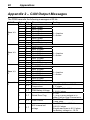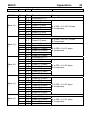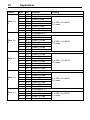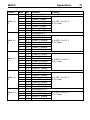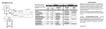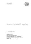
1
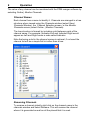
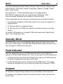
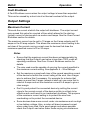
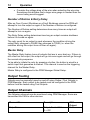
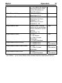
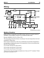
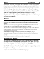
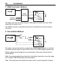
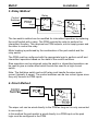
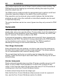
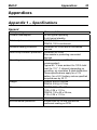
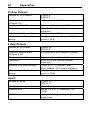
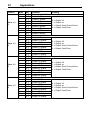
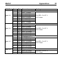
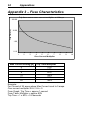
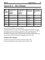
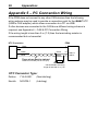
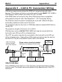
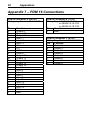
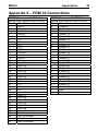
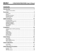
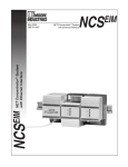
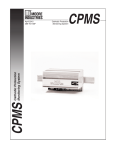
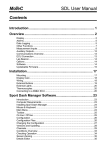
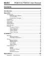
MoTeC
PDM16 & PDM32 User Manual
Contents
Introduction ........................................................................ 3 Operation ............................................................................ 4 Configuration ...........................................................................................4 PDM Manager Software ................................................................4 PC Connection ..............................................................................4 Configuration Concepts.................................................................4 Conditions................................................................................................7 Switch Inputs ...........................................................................................7 CAN Inputs ..............................................................................................8 CAN Output .............................................................................................8 Standby Mode..........................................................................................9 Fault Indicator ..........................................................................................9 Outputs ....................................................................................................9 Paralleled Outputs.......................................................................10 Output Protection ........................................................................10 Output Settings............................................................................11 Output Testing.............................................................................12 Output Channels .........................................................................12 Installation ........................................................................ 14 Mounting ................................................................................................14 Mounting Position........................................................................14 Operating Temperature ...............................................................14 Wiring.....................................................................................................15 Battery Positive ...........................................................................15 Battery Negative..........................................................................16 CAN Wiring..................................................................................16 Input Wiring .................................................................................17 Output Wiring ..............................................................................17 Output Devices ......................................................................................18 Lamps..........................................................................................18 Motors..........................................................................................19 Windscreen Wipers .....................................................................19 Solenoids.....................................................................................22 Electronic Devices.......................................................................23 Appendices....................................................................... 25 Appendix 1 – Specifications ..................................................................25 Appendix 2 – CAN Output Messages....................................................28 Appendix 3 – Fuse Characteristics........................................................34 Appendix 4 – Wire Ratings ....................................................................35 Appendix 5 – PC Connection Wiring .....................................................36 Appendix 6 – CAN & PC Connection Wiring .........................................37 Appendix 7 – PDM 16 Connections ......................................................38 Appendix 8 – PDM 32 Connections ......................................................39 Appendix 9 – Dimensions......................................................................41 PDM16.........................................................................................41 PDM32.........................................................................................42 © Copyright 2007 – MoTeC Pty Ltd
The information in this document is subject to change without notice.
While every effort is taken to ensure correctness, no responsibility will be taken for the consequences of any
inaccuracies or omissions in this manual.
20 June, 2008
MoTeC
Introduction
3
Introduction
The PDM16 and PDM32 replace conventional relays, fuses and circuit
breakers by providing electronically switched power to the various electrical
systems in the vehicle, including motors, lamps, ECUs and data systems. This
simplifies wiring and switch requirements, while increasing reliability.
The PDM16 has 16 outputs and the PDM32 has 32 outputs. Each output is
over-current protected and can be controlled via a combination of switch
inputs, CAN messages and logic functions. In addition to performing simple
functions such as flashing indicator lamps, the logic functions can be used to
selectively turn off systems during low battery voltage or engine starting.
The PDMs also provide full diagnostic information, including output currents
and error status that can be monitored on a PC or transmitted via CAN to a
display or logging device.
Throughout this manual the PDM16 & PDM32 will be referred to as the PDM
except where details specific to a particular product are discussed.
Overview PDM connections
4
Operation
Operation
Configuration
PDM Manager Software
The PDM Manager software is used to:
• Change the PDM's configuration
• Monitor the PDM's operation including the output currents and diagnostics
• Test the outputs by manually turning them off and on
• Update the firmware.
PC Connection
Use a MoTeC UTC (USB to CAN adapter) to connect the PC to the PDM.
Note: the MoTeC CAN cable cannot be used with the PDM.
The PDM requires the mating connector to be wired to it. See Appendix 5 –
PC Connection Wiring for details.
Configuration Concepts
The PDM requires various settings to be configured such as the maximum
current settings for the outputs and the circumstances in which to turn the
outputs on.
Configuration Files
The configuration settings are stored in a configuration file on the PC.
The configuration file can be changed without the PC being connected to the
PDM.
The configuration file can be sent to the PDM by using Online | Send
Configuration in PDM Manager.
MoTeC
Operation
5
Serial Number
The PDM serial number must be entered as part of a PDM configuration file.
A configuration file can only be sent to the PDM with the matching serial
number.
This allows multiple PDMs to be used without special device configuration
requirements and also ensures that the PDMs have the correct configuration
file.
When performing online activities such as Monitor Channels, PDM Manager
will connect to the PDM with the serial number of the loaded configuration file.
If there is no file loaded then the serial numbers for all connected PDMs will
be displayed allowing any PDM to be selected.
To enter the serial number, select the Global Setup item in the configuration
tree.
Updating Firmware
To control the PDM operation, the PDM contains software – referred to as
firmware.
The firmware in the PDM is updatable which allows the operation of the PDM
to be updated when new versions become available.
The version of the PDM firmware must match the firmware version distributed
with the PDM Manager software.
When a new version of the PDM Manager software is installed on the PC the
PDM firmware needs to be updated as well.
The firmware can be updated using Online | Update Firmware in PDM
Manager.
Channels
Channels are used to link the various systems within the PDM configuration.
For example: The input pin system generates a channel for each configured
input pin. Depending on the state of the input pin the channel value will be
zero or one. The resulting channel can be selected to control a particular
output, or used as an input to a complex logic function (a “condition”) that
combines a number of channels to create a new channel. This new channel
can then be used to control an output, or as an input to another condition.
Each channel can only be generated once, but may be used in multiple
outputs and conditions.
6
Operation
The value of any channel can be monitored with the PDM manger software by
selecting Online | Monitor Channels.
Channel Names
Each channel has a name to identify it. Channels are arranged in a tree
structure when viewed using the Channels window (select View |
Channels Window), the Channel Selection screen, or the Monitor
Channels screen (select Online | Monitor Channels).
The tree structure is formed by including a dot between parts of the
channel name. For example: Indicator.Left and Indicator.Right would
appear as Left and Right under a node called Indicator.
Note that using a dot in the channel names is optional, if not used the
channel list will be a simple flat list rather than a tree.
Renaming Channels
To rename a channel globally right click on the channel name in the
channels window and select Rename. This will rename the channel
where it is generated as well as all the placed that it is used.
MoTeC
Operation
7
Conditions
Conditions are used to form complex logic expressions that can generate new
channels or control when an output is turned off or on.
A condition takes one or more channels and performs one or more logic
operations on these channels. The logic operations include AND, OR, flash
and many more.
A condition generates a new channel with a value of either TRUE (1) or
FALSE (0).
This channel can be used to control an output or it can be the used in another
condition.
Number of Operations
There are a total of 200 logic operations available in the PDM.
The number of operations used is shown in the status line.
Switch Inputs
The PDM Switch Inputs are intended for use with a switch that is directly
wired between a PDM input pin and the PDM 0V pin.
It is possible to connect to a switch that is wired to another system in the
vehicle. In this case, ensure that the voltage levels are set appropriately as
there may be ground voltage variations between devices.
Each input calibration results in a channel with a value of either 0 or 1, which
can be used in a condition or to directly control an output.
The resulting channel value and the input voltage may be viewed in Online |
Monitor Channels or Online | Monitor PDM.
The trigger voltages are fully programmable. The recommended trigger
voltages are approximately 3.5 V for the low threshold and 4.2 V for the high
threshold. The high threshold should be set below 6 V to ensure detection of a
high level signal when the battery voltage is low.
To avoid switch bounce and/or to delay recognition when the switch changes
state, the inputs also have programmable trigger times. A trigger time of 0.1
second will normally reject switch bounce.
8
Operation
CAN Inputs
The PDM can receive CAN messages allowing the outputs to be controlled by
other devices.
The PDM receives CAN messages on any of four sequential CAN IDs. The
IDs must be within the standard address range.
To enter the base CAN address select the Global Setup item in the
configuration tree.
Channels are extracted from the CAN messages by specifying a CAN
address and an offset. The offset determines which byte in the message is
used.
Each CAN generated channel will be set to zero on start-up until a matching
CAN message is received.
If any of the CAN messages are not received for 1 second then the
corresponding timeout channel will be set to TRUE. This channel can be used
in a condition if required. During the CAN timeout period the channel value
remains at the last received value.
8 Bit Values
The PDM can receive 8 bit values, which can be used directly or masked with
a bit mask.
16 Bit Values
The PDM may receive 16 bit signed values. A divide factor must be specified
to reduce the value to fit into the 8 bit result channel which has a range of 0 to
255 (unsigned).
For example, a 16 bit RPM value with resolution of 1 RPM could be divided by
100 to give a value with a resolution of 100 RPM. The maximum channel
value of 255 will be equivalent to 25500 RPM.
If the value after division is greater than 255 then the result value will be
clamped to 255. The PDM treats the received value as a signed 16-bit value
(i.e. -32768 to 32767). Negative values are clamped to 0.
CAN Output
A fixed set of messages are sent to other devices via CAN.
MoTeC
Operation
9
The CAN messages include: Output Voltage, Output Current, Output Load,
Output Status, Input State, Internal Temperature, Battery Voltage, Global
Error, Total Current.
See Appendix 2 – CAN Output Messages for message details.
Most MoTeC logging devices can receive these messages. CAN
communications templates are available for these devices.
These messages can be received by another device and used as follows
• For diagnostic purposes; Particularly useful if the values are logged in a
logging device.
• To show an alarm on a display device.
• To use the value of a PDM input switch to activate a feature in another
device.
To set the CAN address or to disable CAN output select the Global Setup
item in the configuration tree.
Standby Mode
The PDM enters a low current Standby Mode when all outputs are off and
there is no CAN activity. The PDM exits Standby Mode when the state of any
input changes or CAN activity resumes.
Fault Indicator
When an output fault occurs the PDM sets the value of the Global Error
channel to TRUE (PDM.Global Error). This can be used in the following ways:
• A display device may receive the Global Error channel via CAN and show
an alarm message and activate an alarm light.
• A fault indicator light can be connected to any PDM output. The output
should be configured to turn on when the Global Error channel is TRUE.
Outputs
All outputs are high side type outputs; they switch Batt+ to the output pin.
All outputs have hardware thermal overload protection, fault logic and overcurrent logic.
10
Operation
Paralleled Outputs
Two or more output pins can be connected in parallel to increase current
capacity. Outputs that are connected in parallel must all be of the same type
(either all 8 amp or all 20 amp).
Paralleled outputs must be configured to use a common channel or an
identical condition to activate them.
Output Protection
Over-Current Shutdown
An Over-Current Shutdown occurs when the Output Load value exceeds
100% which corresponds to the maximum current setting.
The Output Load value is filtered so that it normally increases (and
decreases) slowly, modelling how the temperature of a wire responds to the
current flowing through it.
The resultant characteristic is very similar to a thermal circuit breaker which is
often used in motor-sport applications, It is also similar to a slow blow fuse.
See Appendix 3 – Fuse Characteristics for details.
The filtering of the load value ensures that the start-up current (inrush current)
of motors and lamps does not cause the output to shutdown during this
period. It also allows for short term overloads to occur without the output
shutting down.
A large over-current such as a short circuit will cause the Output Load value
to increase rapidly, causing the output to shutdown in a short period of time to
protect the wire and the PDM output. Note that in some cases a short circuit
may cause a Fault Shutdown before the Over-Current Shutdown occurs.
The amount of filtering is not adjustable and is set with a time constant of 20
to 50 seconds based on the maximum current setting. These values have
been determined to conservatively suit the appropriate wire gauge for the
selected current setting.
Tips
• The Output Load and Output Current values are transmitted on CAN
so that they can be logged by another device. Check the logged
Output Load value to ensure it is not too close to 100% during
normal operation and during start-up.
• The Output Load and Output Current values can also be monitored
using PDM Manager.
MoTeC
Operation
11
Fault Shutdown
A Fault Shutdown occurs when the output voltage is lower than expected.
This can be caused by a short circuit or thermal overload of the output.
Output Settings
Maximum Current
This sets the current at which the output will shutdown. The output current
may exceed this value for a period of time which allows for the start-up
(inrush) current of devices such as motors and lamps. See the Over-Current
Shutdown section for details.
The maximum current can be set to 10 amps on the 8 amp outputs and 25
amps on the 20 amp outputs. This allows the maximum current setting to be
set clear of the normal running current even for devices that draw the
maximum specified current of 8 or 20 amps.
Notes
• Ensure that the maximum current has been set appropriately by
checking that the Output Load value is less than 100% under all
operating conditions. See Over-Current Shutdown section for
details.
• The wire used must be capable of carrying the current specified in
the maximum current setting. See Appendix 4 – Wire Ratings.
• Set the maximum current well clear of the normal operating current
of the device but within the current rating of the wire. Use a larger
wire to achieve this if necessary. For example for a device that
draws no more than 5 amps (except at start-up) use a wire that is
rated at 8 amps and set the maximum current to 8 amps to give a
clear margin.
• Don't try and protect the connected device by setting the current
close to the normal current of the device as this is unlikely to be
effective and could result in an inadvertent shutdown. The purpose
of the maximum current setting is to protect the wire from
overheating not to protect the connected device.
• Some devices draw more current under circumstances such as high
or low battery voltage. Also, a motor will draw increased current
when under more load. Set a good margin and where possible
check the Output Load value under these varying circumstances.
12
Operation
• Consider the voltage drop of the wire when selecting the wire size.
Sometimes this dictates that a larger wire gauge is needed than the
current rating would suggest.
Number of Retries & Retry Delay
After an Over-Current Shutdown or a Fault Shutdown occurs the PDM will
attempt to turn the output on again if the Number of Retries is configured.
The Number of Retries setting determines how many times an output will
attempt to turn on again.
The Retry Delay setting determines how long an output remains shutdown
before it is turned on again.
The retry count for an output is reset whenever the condition driving the
output firstly changes to FALSE then changes to TRUE (i.e. when the
condition driving the output turns off then on again).
Master Retry
The Master Retry feature turns all outputs that are in error back on. If there is
still a fault on the output, the output will go into error again and will go through
the normal retry sequence.
To be able to initiate the retry by pressing a button, the button is wired to a
switch input that generates a channel. This channel is used as the triggering
channel for the Master Retry.
Master Retry is configured in the PDM Manager Global Setup.
Output Testing
Outputs may be manually turned on and off using Online | Test Outputs in
PDM Manager. Each output to be tested must be configured in the PDM
before it can be tested using Test Outputs.
Output Channels
The following channels can be monitored using PDM Manager. Some are
transmitted via CAN to other devices.
Channel Name
Description
OutputName
Output Control Status
0 = Off
CAN
Output
No*
MoTeC
OutputName.Voltage
OutputName.Current
OutputName.Load
OutputName.Status
OutputName.Status.Active
OutputName.Status.OverCurrent
OutputName.Status.Fault
Operation
1 = On (Note: the output
may be off due to Overcurrent Shutdown or
Fault Shutdown)
Voltage on the output
Resolution 0.2 V
Output Current in amps
Resolution 0.5 A on
Outputs 1 – 8
Resolution 0.2 A on
Outputs 9 – 32
Output Load. Filtered
current as a percentage
of the maximum current
setting.
Resolution 1%
0 = Off
1 = On Active
2 = Over-Current
Shutdown
4 = Fault Shutdown
0 = Output is off
1 = Output is on
0 = OK
1 = Over-Current
Shutdown
0 = OK
1 = Fault Shutdown
13
Yes
Yes
Yes
Yes
No
(use status)
No
(use status)
No
(use status)
* use Status – a non-zero Status value means that the output should be on
14
Installation
Installation
Mounting
Mounting Position
Mount in a well ventilated area. Do not mount the PDM against a hot surface.
Operating Temperature
CAUTION: The PDM may get very hot, do not touch the PDM during
operation.
The internal temperature of the PDM should not exceed the value in the
specifications. The temperature can be checked on the Monitor Channels or
Monitor PDM screen in PDM Manager, it is also transmitted via CAN allowing
it to be logged. Note that the temperature may take 30 minutes or more to
stabilise.
The temperature will depend on the total load current; a higher current will
cause a higher temperature. It is also highly dependent on ambient
temperature and how the PDM is mounted.
If the internal temperature exceeds the specifications, cooling may be
achieved by one or more of the following:
• Relocating the PDM to a cooler mounting position
• Increasing air circulation around the PDM case
• Ducting cool air over the PDM case
• Fitting a heatsink to the back surface of the PDM case
MoTeC
Installation
15
Wiring
PDM wiring overview
Battery Positive
Battery positive is supplied to the PDM via the single pin connector which is
available in three different variants to suit different cable sizes.
Deutsch ASHD614-1S-C16, C25 or C35
The wire gauge should be chosen according to the wire temperature limit and
acceptable voltage drop.
Note that the temperature of the wire is affected by the ambient temperature,
air circulation, current, wire gauge, the temperature of any surrounding wires
and the covering sheath.
C16 contact suits 6# wire (90 A max*)
C25 contact suits 4# wire (120 A max*)
C35 contact suits 2# wire (150 A max*)
*Approximate rating for Tefzel insulated wire in free air, 80 °C ambient. Tefzel
wire must not exceed 150 °C.
16
Installation
Battery Isolator Switch
Battery positive must generally be connected through an isolator switch or
relay.
The isolator must isolate the battery from all devices in the vehicle including
the PDM, starter motor and alternator. The isolator must be rated to handle
the starter motor current.
When the battery is isolated the engine may run on due to power supplied by
the alternator. To avoid this, the isolator switch should have a secondary
switch that is connected to a shutdown input on the ECU. If the ECU does not
have a shutdown input then the switch can be connected to a PDM input,
which can then turn off power to the ignition system or the ECU, which will
cause the engine to stop.
Battery Negative
Both of the Batt– pins should be wired to battery negative via 20# wire.
These pins normally only carry the very low operating current however during
a load dump they carry the load dump current which may be 50 amps or
higher.
CAN Wiring
PC Communications
In order for a PC to communicate with the PDM a mating connector for the
MoTeC UTC (USB to CAN adapter) must be wired to the PDM CAN port.
If there are no other CAN devices see Appendix 5 – PC Connection Wiring
otherwise see Appendix 6 – CAN & PC Connection Wiring.
Communications to other Devices
The PDM transmits messages that may be received by other devices
connected to the same CAN bus.
The CAN communication rate in the other devices must be set to the same
speed as in the PDM (1 Mbit/sec)
The CAN bus must be wired according to Appendix 6 – CAN & PC
Connection Wiring.
MoTeC
Installation
17
Input Wiring
The PDM Switch Inputs are intended for use with a switch that is directly
wired between a PDM input pin and the PDM 0V pin.
It is possible to connect to a switch that is wired to another system in the
vehicle. In this case ensure that the voltage levels are set appropriately as
there may be ground voltage variations between devices.
Each input has an internal 10 kohm pull-up resistor to Batt+.
Tip
• If standby current is important, wire the switches so that they are
normally open during standby as this will reduce the standby
current.
Input Switch Connected to Battery
If an input is driven from a device that switches to battery then an external
pull-down resistor is required.
If possible the switch should be rearranged so that it switches to 0V to avoid
the need for the resistor. In some cases this is not possible, for example if the
signal comes from an electronic device such an ECU that has an output that
can only switch to battery. This could be a signal that indicates when to turn
the full pump on.
The resistor should be 1500ohms 1/4watt and should be connected between
the input pin and the 0V pin. The input trigger levels should be set to 4V and
5V to guarantee correct triggering for all possible battery voltages.
Output Wiring
All outputs are high side type outputs; they switch Batt+ to the output pin.
All outputs have hardware thermal overload protection, fault logic and overcurrent logic.
Paralleled Outputs
Two or more output pins can be connected in parallel to increase current
capacity. Outputs that are connected in parallel must all be of the same type
(either all 8 amp or all 20 amp).
Paralleled outputs must be configured to use a common channel or an
identical condition to activate them.
18
Installation
Wire Gauges
The wire gauge must be chosen to suit the current consumed by the
connected device and to ensure that the voltage drop is acceptable.
On long runs it may be necessary to use a heavier gauge wire to minimise
voltage drop.
The wire gauge must also be compatible with the connectors pin; using a
smaller than recommended wire gauge may result in a poor crimp.
Suitable wire gauges for the 8 amp outputs are 24# to 20#
Suitable wire gauges for the 20 amp outputs are 20# to 16#
See Appendix 4 – Wire Ratings.
Output Devices
Lamps
Tungsten Lamps
Typically used for tail lights, indicator lights and general lighting.
Tungsten lamps draw additional current during turn on. Typically this peaks at
about 5 times the steady state current and dies out in about 0.1 second. The
PDM will largely ignore this due to the Output Load filtering (see the OverCurrent Shutdown section for details)
Halogen Lamps
Halogen lamps are commonly used in headlights and are more efficient than
Tungsten lamps.
Halogen lamps have similar characteristics to Tungsten lamps.
Xenon (HID) Lamps
Xenon lamps are also used in headlights and are more efficient than
Tungsten and Halogen lamps.
Xenon lamps have a long duration inrush current that peaks at about 4 times
the steady state current. The inrush current decays over a period of about 10
seconds. This puts a high load on the PDM output during start-up.
To avoid Over-Current Shutdown during start-up it may be necessary to set a
higher Maximum Current than normal. For example a Xenon lamp with a
MoTeC
Installation
19
steady state current of 3 amps may need a Maximum Current setting of 6 to
8 amps to avoid Over-Current Shutdown during start-up, particularly if the
battery voltage is low. Note that the wire should also be rated at this current.
Unlike other lamps Xenon lamps draw more current as the battery voltage
decreases. At 10 volts the lamp will draw 40% more current than at 14 volts.
For example a lamp that draws 3 amps at 14 volts will draw 4.2 amps at 10
volts. This must be allowed for when setting the Maximum Current.
To ensure that the Maximum Current is set appropriately, check that the
Output Load value stays safely below 100% during turn on when the battery is
at 12 volts (not charging).
Motors
Electric motors draw additional current during start-up. Typically the start-up
current is 3 to 5 times the steady state current and it dies out in less than a
second.
This start-up current is largely ignored by the PDM due to the Output Load
filtering (see the Over-Current Shutdown section for details).
The current in a motor increases with increasing load on the motor. A motor
draws maximum current when it is stalled. The Maximum Current setting
should take this into account.
Note that a motor may draw more current as it or the device that it is
connected to ages, This should be allowed for when setting the Maximum
Current.
Note that motor speed control is currently not supported.
Windscreen Wipers
The PDM can drive windscreen wiper motors; however the PDM cannot be
connected to both the fast and slow motor windings at the same time. This is
due to the voltage generated by the slow winding during fast operation which
will cause braking of the motor and possibly damage the PDM.
Note that the following schematics are shown for 'common-ground' wiper unit.
Some wiper units have 'common-positive' in which case the schematics must
be adjusted accordingly.
A wiper unit can be wired in one of the following ways.
20
Installation
1. OEM Controller Method
Output
S
PDM
OEM
controller
Control
Switches
M
F
Home
Park
Switch
The wiper unit can be wired using an OEM wiper controller with the PDM
supplying the power only.
The OEM controller normally performs the intermittent and motor braking
functions.
2. Two Switch Method
The wiper unit can be wired in a simple two switch arrangement; one switch
for power and the other to select fast or slow. The PDM supplies power only.
Motor braking is performed by the combination of the park switch and the
on/off switch.
Note: this arrangement cannot perform intermittent operation since the wiper
will not park if the PDM simply removes power.
Note: The switches must handle the wiper motor current (typically 4 amps).
MoTeC
Installation
21
3. Relay Method
Relay
Control
Switches
Output
PDM
Output
Slow
On
Off
S
M
Fast
F
Home
Park
Switch
The two switch method can be modified for intermittent operation by replacing
the on/off switch with a relay. The PDM controls the relay to perform the
intermittent function. This requires two PDM outputs; one to supply power and
the other to control the relay.
Motor braking is performed by the combination of the park switch and the
relay switch.
The PDM must be configured with the appropriate logic to perform on/off and
intermittent operation based on the state of the control switches.
Slow operation can be achieved using the switch or intermittent operation can
be used to give a similar effect which avoids the need for a high current
switch.
Note: The fast/slow switch and on/off relay must handle the wiper motor
current (typically 4 amps). The control switches can be low current types since
they only connect to PDM inputs
4. Direct Method
The wiper unit can be wired directly to the PDM as long as it is only connected
to one output.
In this method the park switch is wired directly to a PDM input so the park
logic must be configured in the PDM.
22
Installation
This method requires the use of Output 9 which performs motor braking. The
PDM performs motor braking by momentarily shorting the output to ground
when the output turns off.
The PDM must be configured with the appropriate logic to perform on/off and
intermittent operation based on the state of the control switches.
Slow operation can be achieved using a switch between the fast and slow
windings as used in the other methods or intermittent operation can be used
to wipe less frequently.
The control switches can be low current types since they only connect to PDM
inputs.
Solenoids
The current drawn by a normal single coil solenoid ramps up from zero to its
steady state value over a period of time. The time taken to do this depends on
the inductance and resistance of the solenoid but is normally very short (less
than 0.1 second). This has no affect on the PDM.
A solenoid will generate a voltage spike when turned off; this is clamped and
absorbed by the PDM. The amount of energy absorbed by the PDM depends
on the inductance and current in the solenoid. The PDM is capable of
absorbing the energy of most normal solenoids in a vehicle.
Two Stage Solenoids
Some solenoids have two windings; one that is used to turn the solenoid on
the other that is used to hold it on once it has switched. This allows optimum
turn on characteristics with minimum holding current.
The current drawn by the turn on winding may be higher than the holding
winding. Check that the Output Load is well clear of 100% during turn on and
during holding.
Starter Solenoids
Starter solenoids typically draw more than 20 amps, possibly as much as 40
amps. In many cases it is still possible to run them from a single 20 amp
output. In this case the output will shut down after about 10 to 20 seconds of
cranking due to the Over-Current Shutdown feature.
A starter solenoid may also be two stage type.
Note that the Over-Current Shutdown allows excess current for a period of
time, see the Over-Current Shutdown section for details.
MoTeC
Installation
23
In this case the wire can be rated for 20 amps, unless the voltage drop
dictates that it should be larger. This method may also ensure that the starter
motor does not overheat during excess cranking.
Alternatively two 20 amp outputs may be paralleled allowing cranking for any
period of time (subject to overheating of the starter motor).
Electronic Devices
The PDM can supply power to electronic devices such as engine
management systems, data acquisition systems, radios etc.
Many electronic devices will have a short inrush current. The PDM will largely
ignore this due to the Output Load filtering (see the Over-Current Shutdown
section for details)
The PDM provides reverse battery protection to protect itself and the
connected devices.
The PDM provides load dump clamping to protect itself and to help protect the
connected devices.
Ignition Systems
Inductive Ignition Systems
Most inductive ignition systems draw a peak current of about 8amps,
some draw as much as 20 Amps however the average current is much
less.
In most cases inductive ignition systems can be connected to an 8amp
output however the Output Load current must be checked to ensure it
stays well clear of 100%.
Note that the average current will increase with increasing RPM so the
Output Load should be checked at maximum RPM.
CDI Ignition Systems
CDI Ignition systems can draw peak currents of as much as 50 Amps. It
is recommended that all CDI ignition systems are connected to a
20Amp output.
Note that the average current will increase with increasing RPM so the
Output Load should be checked at maximum RPM.
24
Installation
Engine Management Systems
The current drawn by an engine management system will depend on the type
of loads it is connected to and the operating conditions.
Fuel injectors draw current in pulses. The maximum average current drawn by
the fuel injectors is when they are at maximum duty cycle.
For servo devices such as Drive by Wire motors maximum current is drawn
when making large transitions.
Check that the Output Load is clear of 100% under worst case operating
conditions, i.e. when the injectors are operating at maximum duty cycle, servo
devices such as drive by wire motors are making large transitions and any
auxiliary loads are drawing maximum current.
MoTeC
Appendices
25
Appendices
Appendix 1 – Specifications
General
Battery voltage
Current consumption
Total output current
Reverse battery protection
Load dump transient protection
Operating temperature
Weight
Dimensions
Case
Environmental protection
30 V max, 6.5 V min
35 mA typical operating
5 mA typical standby
PDM32: 120 A continuous
PDM16: 100 A continuous
Protection for PDM and all connected
devices
Protection for PDM.
Also assists in protecting connected
devices.
110 °C max internal (100 °C
recommended)
Typical 85 °C max ambient for 120 A total
load (for 110 ° C internal) depending on
mounting, air circulation & load distribution.
These specifications apply for a 12V
battery, for a 24 V battery reduce specified
temperatures by 20 °C.
PDM32: 405 g, 0.89 lbs
PDM16: 330 g, 0.72 lbs
PDM32: 180 x 60 x 28 mm,
7.09 x 2.36 x 1.10 in
PDM16: 130 x 60 x 28 mm,
5.12 x 2.36 x 1.10 in
Machined aluminium
Rubber seal on lid and connectors,
conformal coating on PCB
26
Appendices
20 Amp Outputs
Number of 20 A outputs
Maximum output current
(Outputs 1-8)
Over-current shutdown
Protection
Inductive load clamp voltage
Maximum inductive load
energy
PDM32: 8
PDM16: 8
20 A continuous, 115 A transient (typical)
Programmable in steps of 1 A
Short circuit and thermal overload
protection
-17 V (relative to Batt-)
1.5 J (junction temperature = 150 °C, load
current = 20 A)
8 Amp Outputs
Number of 8 A outputs
Maximum output current
(Outputs 9-32)
Over-current shutdown
Protection
Inductive load clamp voltage
Maximum inductive load
energy
PDM32: 24
PDM16: 8
8 A continuous, 60 A transient (typical)
Programmable in steps of 1 A
Short circuit and thermal overload
protection
Output 9: -0.7 V (relative to Batt-)
Other Outputs: -42 V (relative to Batt+)
0.3 J (junction temperature = 150 °C, load
current = 20 A)
Inputs
Number of inputs
Pull-up resistor
Measurement
Calibration
PDM32: 23
PDM16: 12
10 k to Batt+
Range of 0 to 51 V, resolution 0.2 V
(8 bits)
High and low trigger voltage, high and low
trigger times
MoTeC
Appendices
CAN Input
Number of messages
4 messages, 8 bytes per message
CAN Output
Message rate
20 Hz
27
28
Appendices
Appendix 2 – CAN Output Messages
The PDM transmits the following messages at 20 Hz.
CAN ID
Base Id +
0
Base Id +
0
Base Id +
0
Base Id +
0
Byte
0
0
1
2
3
4
5
6
7
0
0
1
2
3
4
5
6
7
0
0
1
2
3
4
5
6
0
Bit
4..7
0
0
0
0
0
0
0
0
4..7
0
0
0
0
0
0
0
0
4..7
0
0
0
0
0
0
0
4..7
Channel
Compound Id = 0
Input 1 State
Input 2 State
Input 3 State
Input 4 State
Input 5 State
Input 6 State
Input 7 State
Input 8 State
Compound Id = 1
Input 9 State
Input 10 State
Input 11 State
Input 12 State
Input 13 State
Input 14 State
Input 15 State
Input 16 State
Compound Id = 2
Input 17 State
Input 18 State
Input 19 State
Input 20 State
Input 21 State
Input 22 State
Input 23 State
Compound Id = 3
PDM Internal
Temperature
1
0..7
2
0..7
PDM Battery Voltage
3
0..7
Global Error Flag
4
0..7
Total Current
5
0..7
9.5V internal rail
voltage
Scaling
0 = Inactive
1 = Active
0 = Inactive
1 = Active
0 = Inactive
1 = Active
0 to 125 = 0 °C to +125 °C
1 °C steps
0 to 255 = 0 V to 31 V
0.1216 V steps
0 = OK
1 = one or more outputs is in
either Fault or Over-Current error
0 to 255 = 0 to 255 amps
1 amp steps
0 to 255 = 0 V to 15.68 V
0.0615 V steps
Should read close to 9.5 V when
the Battery voltage is > 10.5V
MoTeC
CAN ID
Base Id +
1
Base Id +
1
Base Id +
1
Base Id +
1
Base Id +
1
Appendices
6
0..7
Reset Source
Byte
0
1
2
3
4
5
6
7
0
Bit
0..7
0..7
0..7
0..7
0..7
0..7
0..7
0..7
0..7
Channel
Compound Id = 0
Output 1 Current
Output 2 Current
Output 3 Current
Output 4 Current
Output 5 Current
Output 6 Current
Output 7 Current
Compound Id = 1
1
0..7
Output 8 Current
2
3
4
5
6
7
0
1
2
3
4
5
6
7
0
1
2
3
4
5
6
7
0
1
2
3
4
0..7
0..7
0..7
0..7
0..7
0..7
0..7
0..7
0..7
0..7
0..7
0..7
0..7
0..7
0..7
0..7
0..7
0..7
0..7
0..7
0..7
0..7
0..7
0..7
0..7
0..7
0..7
Output 9 Current
Output 10 Current
Output 11 Current
Output 12 Current
Output 13 Current
Output 14 Current
Compound Id = 2
Output 15 Current
Output 16 Current
Output 17 Current
Output 18 Current
Output 19 Current
Output 20 Current
Output 21 Current
Compound Id = 3
Output 22 Current
Output 23 Current
Output 24 Current
Output 25 Current
Output 26 Current
Output 27 Current
Output 28 Current
Compound Id = 4
Output 29 Current
Output 30 Current
Output 31 Current
Output 32 Current
Scaling
0 to 255 = 0 to 127.5 amps
0.5 amp steps
0 to 255 = 0 to 127.5 amps
0.5 amp steps
0 to 255 = 0 to 51 amps
0.2 amp steps
0 to 255 = 0 to 51 amps
0.2 amp steps
0 to 255 = 0 to 51 amps
0.2 amp steps
0 to 255 = 0 to 51 amps
0.2 amp steps
29
30
CAN ID
Base Id +
2
Base Id +
2
Base Id +
2
Base Id +
2
Base Id +
2
Appendices
Byte
0
1
2
3
4
5
6
7
0
1
2
3
4
5
6
7
0
1
2
3
4
5
6
7
0
1
2
3
4
5
6
7
0
1
2
3
4
Bit
0..7
0..7
0..7
0..7
0..7
0..7
0..7
0..7
0..7
0..7
0..7
0..7
0..7
0..7
0..7
0..7
0..7
0..7
0..7
0..7
0..7
0..7
0..7
0..7
0..7
0..7
0..7
0..7
0..7
0..7
0..7
0..7
0..7
0..7
0..7
0..7
0..7
Channel
Compound Id = 0
Output 1 Load
Output 2 Load
Output 3 Load
Output 4 Load
Output 5 Load
Output 6 Load
Output 7 Load
Compound Id = 1
Output 8 Load
Output 9 Load
Output 10 Load
Output 11 Load
Output 12 Load
Output 13 Load
Output 14 Load
Compound Id = 2
Output 15 Load
Output 16 Load
Output 17 Load
Output 18 Load
Output 19 Load
Output 20 Load
Output 21 Load
Compound Id = 3
Output 22 Load
Output 23 Load
Output 24 Load
Output 25 Load
Output 26 Load
Output 27 Load
Output 28 Load
Compound Id = 4
Output 29 Load
Output 30 Load
Output 31 Load
Output 32 Load
Scaling
0 to 255 = 0 to 255%
1% steps
0 to 255 = 0 to 255%
1% steps
0 to 255 = 0 to 255%
1% steps
0 to 255 = 0 to 255%
1% steps
0 to 255 = 0 to 255%
1% steps
MoTeC
CAN ID
Base Id +
3
Base Id +
3
Base Id +
3
Base Id +
3
Base Id +
3
Appendices
Byte
0
1
2
3
4
5
6
7
0
1
2
3
4
5
6
7
0
1
2
3
4
5
6
7
0
1
2
3
4
5
6
7
0
1
2
3
4
Bit
0..7
0..7
0..7
0..7
0..7
0..7
0..7
0..7
0..7
0..7
0..7
0..7
0..7
0..7
0..7
0..7
0..7
0..7
0..7
0..7
0..7
0..7
0..7
0..7
0..7
0..7
0..7
0..7
0..7
0..7
0..7
0..7
0..7
0..7
0..7
0..7
0..7
Channel
Compound Id = 0
Output 1 Voltage
Output 2 Voltage
Output 3 Voltage
Output 4 Voltage
Output 5 Voltage
Output 6 Voltage
Output 7 Voltage
Compound Id = 1
Output 8 Voltage
Output 9 Voltage
Output 10 Voltage
Output 11 Voltage
Output 12 Voltage
Output 13 Voltage
Output 14 Voltage
Compound Id = 2
Output 15 Voltage
Output 16 Voltage
Output 17 Voltage
Output 18 Voltage
Output 19 Voltage
Output 20 Voltage
Output 21 Voltage
Compound Id = 3
Output 22 Voltage
Output 23 Voltage
Output 24 Voltage
Output 25 Voltage
Output 26 Voltage
Output 27 Voltage
Output 28 Voltage
Compound Id = 4
Output 29 Voltage
Output 30 Voltage
Output 31 Voltage
Output 32 Voltage
Scaling
0 to 255 = 0 to 51 V
0.2 V steps
0 to 255 = 0 to 51 V
0.2 V steps
0 to 255 = 0 to 51 V
0.2 V steps
0 to 255 = 0 to 51 V
0.2 V steps
0 to 255 = 0 to 51 V
0.2 V steps
31
32
CAN ID
Base Id +
4
Base Id +
4
Base Id +
4
Base Id +
4
Appendices
Byte
0
0
1
2
3
4
5
6
7
0
0
1
2
3
4
5
6
7
0
0
1
2
3
4
5
6
7
0
0
1
2
3
4
5
6
7
Bit
6..7
0..5
0..7
0..7
0..7
0..7
0..7
0..7
0..7
6..7
0..5
0..7
0..7
0..7
0..7
0..7
0..7
0..7
6..7
0..5
0..7
0..7
0..7
0..7
0..7
0..7
0..7
6..7
0..5
0..7
0..7
0..7
0..7
0..7
0..7
0..7
Channel
Compound Id = 0
Output 1 Status
Output 2 Status
Output 3 Status
Output 4 Status
Output 5 Status
Output 6 Status
Output 7 Status
Output 8 Status
Compound Id = 1
Output 9 Status
Output 10 Status
Output 11 Status
Output 12 Status
Output 13 Status
Output 14 Status
Output 15 Status
Output 16 Status
Compound Id = 2
Output 17 Status
Output 18 Status
Output 19 Status
Output 20 Status
Output 21 Status
Output 22 Status
Output 23 Status
Output 24 Status
Compound Id = 3
Output 25 Status
Output 26 Status
Output 27 Status
Output 28 Status
Output 29 Status
Output 30 Status
Output 31 Status
Output 32 Status
Scaling
0 = Output off
1 = Output on
2 = Output Over-Current Error
4 = Output Fault Error
0 = Output off
1 = Output on
2 = Output Over-Current Error
4 = Output Fault Error
0 = Output off
1 = Output on
2 = Output Over-Current Error
4 = Output Fault Error
0 = Output off
1 = Output on
2 = Output Over-Current Error
4 = Output Fault Error
MoTeC
CAN ID
Base Id +
5
Base Id +
5
Base Id +
5
Base Id +
5
Appendices
Byte
0
1
2
3
4
5
6
7
0
1
2
3
4
5
6
7
0
1
2
3
4
5
6
7
0
1
2
Bit
0..7
0..7
0..7
0..7
0..7
0..7
0..7
0..7
0..7
0..7
0..7
0..7
0..7
0..7
0..7
0..7
0..7
0..7
0..7
0..7
0..7
0..7
0..7
0..7
0..7
0..7
0..7
Channel
Compound Id = 0
Input 1 Voltage
Input 2 Voltage
Input 3 Voltage
Input 4 Voltage
Input 5 Voltage
Input 6 Voltage
Input 7 Voltage
Compound Id = 1
Input 8 Voltage
Input 9 Voltage
Input 10 Voltage
Input 11 Voltage
Input 12 Voltage
Input 13 Voltage
Input 14 Voltage
Compound Id = 2
Input 15 Voltage
Input 16 Voltage
Input 17 Voltage
Input 18 Voltage
Input 19 Voltage
Input 20 Voltage
Input 21 Voltage
Compound Id = 3
Input 22 Voltage
Input 23 Voltage
Scaling
0 to 255 = 0 to 51 V
0.2 V steps
0 to 255 = 0 to 51 V
0.2 V steps
0 to 255 = 0 to 51 V
0.2 V steps
0 to 255 = 0 to 51 V
0.2 V steps
33
34
Appendices
Appendix 3 – Fuse Characteristics
Trip tim e verses over current m ultiplier at 10Am ps
Trip Time (s)
100.00
10.00
1.00
0.10
1
2
3
Max Current Setting [A]
4
6
8
10
15
20
4
5
6
7
Over Current Multiplier
8
Trip Time Multiplier
76%
84%
92%
100%
120%
140%
Example:
For Current of 25 amps where Max Current is set to 5 amps.
Over current multiplier 25 A / 5 A = 5
From Graph: Trip Time = approx 1 second
From Table: Multiplier = approx 80%
Trip Time = 1 x 80% = 0.8 seconds
9
10
MoTeC
Appendices
35
Appendix 4 – Wire Ratings
Wire
Gauge
(AWG)
Current Rating
at 80 °C
ambient
[amps]*
Current Rating
at 100 °C
ambient
[amps]*
Resistance
[ohms/m]
Resistance
[ohms/1000
ft]
24#
4.5
4
0.071
22
22#
6
5
0.045
14
20#
8
6
0.028
8.5
18#
11
9
0.018
5.5
16#
15
12
0.014
4.3
14#
22
18
0.009
2.7
*The current ratings above are for Tefzel insulated wire and are an indication
only and will not apply in all circumstances.
The actual maximum current rating is determined by the maximum allowed
temperature for the wire which in the case of Tefzel insulated wire is 150 °C.
The temperature of the wire is affected by many factors including the
temperature of adjacent wires, how the wires are bundled and how the wires
are covered as well as the ambient temperature and the current.
Suitable Wire Gauges
Suitable wire gauges for the 8 amp outputs are 24# to 20#
Suitable wire gauges for the 20 amp outputs are 20# to 16#
36
Appendices
Appendix 5 – PC Connection Wiring
If the PDM does not connect to any other CAN devices then the following
wiring scheme may be used to provide a connection point for the MoTeC UTC
(USB to CAN adapter) which allows connection to a PC via USB.
If other devices are connected to the CAN bus a different wiring scheme is
required, see Appendix 6 – CAN & PC Connection Wiring
If the wiring length is less than 2 m (7 ft) then the terminating resistor is
recommended but not essential.
UTC Connector
1
2
3
4
5
PDM
9
Black
Green
White
Green
White
These wires must be twisted
Minimum one twist per 50 mm (2 in)
100R Resistor
*Not essential if the wiring
length is less than 2 m (7 ft)
UTC Connector Type:
B
Deltron
716-0-0501
(Non-latching)
Neutrik
NC5FDL1
(Latching)
0V
10
CAN-LO
11 CAN-HI
MoTeC
Appendices
37
Appendix 6 – CAN & PC Connection Wiring
CAN wiring requirements where the PDM is to communicate with other
devices. This scheme includes a connection point for the MoTeC UTC (USB to
CAN adapter) which allows connection to a PC via USB.
If the PDM does not connect to any other CAN devices then a simplified
wiring scheme may be used. See Appendix 5 – PC Connection Wiring.
The CAN bus should consist of a twisted pair trunk with 100R (0.25 watt)
terminating resistors at each end of the trunk.
The preferred cable for the trunk is 100R data cable but twisted 22# Tefzel is
usually OK.
The maximum length of the bus is 16 m (50 ft)
CAN devices (such as MoTeC PDM, M800 etc) may be connected to the
trunk with up to 500 mm (20 in) of twisted wire.
The UTC connector may also be connected to the trunk with up to 500 mm
(20 in) of twisted wire. If desired two CAN cable connectors may be used so
that the UTC may be connected to either side of the vehicle.
500 mm
Max
CAN Device
eg BR2
CAN Device
eg M800
0V
CAN-HI
CAN-LO
500 mm
max
CAN-HI
CAN-LO
CAN-HI
CAN-LO
100R
CAN-HI
CAN-LO
1
5
4
Minimum one twist per 50 mm (2 in)
<< CAN Bus >>
100R
UTC
Connector
These wires must be twisted
CAN-HI
CAN-LO
100R Terminating
Resistors at each
end of the CAN Bus
CAN Device
eg PDM
Short CAN Bus
B
If the CAN Bus is less than 2 m (7 ft) long then a single termination resistor
may be used. The resistor should be placed at the opposite end of the UTC
connector.
38
Appendices
Appendix 7 – PDM 16 Connections
PDM16 Connector A (26 Pin)
Mating plug: Deutsch AS616-26SN
Pin
A
B
C
D
E
F
G
H
J
K
L
M
N
P
R
S
T
U
V
W
X
Y
Z
a
b
c
Function
Output 9
Output 10
Output 11
Input 1
Input 2
Input 3
0V
0V
CAN Lo
CAN Hi
Output 12
Output 13
Output 14
Output 15
Output 16
Input 4
Input 5
Input 6
Input 7
Input 8
Input 9
Input 10
Input 11
Input 12
Batt–
Batt–
PDM16 Connector B (1 Pin)
Mating Plug: ASHD614-1S-C16
or ASHD614-1S-C25
or ASHD614-1S-C35
Pin
Function
1
Batt+
PDM16 Connector C (8 Pin)
Mating Plug: Deutsch AS616-08SN
Pin
Function
A
Output 1
B
Output 2
C
Output 3
D
Output 4
E
Output 5
F
Output 6
G
Output 7
H
Output 8
MoTeC
Appendices
39
Appendix 8 – PDM 32 Connections
PDM32 Connector A (37 Pin)
Mating Plug: Deutsch AS614-35SN
Pin
Function
1
Input 1
2
Input 2
3
Input 3
4
Input 4
5
Input 5
6
0V
7
0V
8
0V
9
0V
10
CAN Lo
11
CAN Hi
12
Input 6
13
Input 7
14
Input 8
15
Input 9
16
Input 10
17
Input 11
18
Input 12
19
Input 13
20
Input 14
21
Input 15
22
0V
23
0V
24
0V
25
0V
26
Input 16
27
Input 17
28
Input 18
29
Input 19
30
Input 20
31
Input 21
32
Input 22
33
Input 23
34
Not Connected
35
Not Connected
36
Not Connected
37
Not Connected
PDM32 Connector B (26 Pin)
Mating Plug: Deutsch AS616-26SN
Pin
Function
A
Output 9
B
Output 10
C
Output 11
D
Output 12
E
Output 13
F
Output 14
G
Output 15
H
Output 16
J
Output 17
K
Output 18
L
Output 19
M
Output 20
N
Output 21
P
Output 22
R
Output 23
S
Output 24
T
Output 25
U
Output 26
V
Output 27
W
Output 28
X
Output 29
Y
Output 30
Z
Output 31
a
Output 32
b
Batt–
c
Batt–
40
Appendices
PDM32 Connector C (1 Pin)
Mating Plug: ASHD614-1S-C16
or ASHD614-1S-C25
or ASHD614-1S-C35
Pin
Function
1
Batt+
PDM32 Connector D (8 Pin)
Mating Plug: Deutsch AS616-08SN
Pin
Function
A
Output 1
B
Output 2
C
Output 3
D
Output 4
E
Output 5
F
Output 6
G
Output 7
H
Output 8
MoTeC
Appendix 9 – Dimensions
PDM16
Appendices
41
42
PDM32
Appendices
MoTeC
Notes
43
44
Notes
MoTeC
Notes
45
46
Notes