1
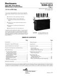
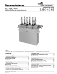
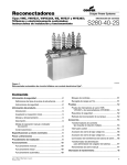
Reclosers
Cooper Power Systems
S280-40-5
Type RVE and WVE, Three-Phase
Maintenance Instructions
24.9 kv
●
400 Amp (Type RVE)
Service Information
560 Amp (TypeWVE)
CAUTION:
This manual, bulletin S280-40-5, for Type RVE and WVE
electronically controlled reclosers covers:
DO NOT ENERGIZE THIS
EQUIPMENT OUT OF OIL
● maintenance of the interrupting mechanism
● operational checks for circuit components
attached to the head casting and mechanism
frame
● testing of the control cable and bushing current
transformers
● replacement of mechanical and electrical com-
ponents
● replacement parts for the interruping
unit
A separate manual, bulletin 280-75-2, is a service manual
which covers the electronic control and provides information
on general inspection, operational checks, and battery testing and charging. Procedures for testing the recloser and
control together are found in the control installation manual,
bulletin S280-75-1.
ORDER OF CONTENTS
Page
Page
Introduction.................................................................1
Rating Changes ........................................................14
Description of Type Recloser ....................................2
Adjustments...............................................................14
General Maintenance Information .............................2
Maintenance Intervals............................................2
Desirable Oil Specifications ...................................4
Operational Checks...................................................14
Control Cable .........................................................15
Circuit Components................................................15
Bushing Current Transformers ...............................17
Periodic Field Inspection and Maintenance..... .........4
Shop Maintenance .....................................................6
Arc Interrupting Assembly
Type RVE Reclosers ...............................................6
Arc Interrupting Assembly
Type WVE Reclosers ..............................................8
Closing Solenoid .....................................................9
Closing Solenoid Contactor ....................................10
Closing Solenoid Fuses ..........................................10
Bushings
Type RVE Recloser ................................................11
Type WVE Recloser ................................................11
Removal of Head Casting ......................................12
Replacement Instructions for
Circuit Components................................................18
Service Parts List
Basic Parts List
Types RVE and WVE Reclosers
Tank and Cover Assemblies...............................21
Closing Solenoid Parts.......................................24
Parts List for Interrupting Mechanism
Type RVE Recloser ............................................26
Parts List for Interrrupting Mechanism,
Type WVE Recloser ..........................................27
Head Mechanism Parts List
Type RVE and WVE Reclosers ..........................28
Mechanism Operation ...............................................13
These instructions do not claim to cover all details or variations in the equipment, procedure, or process described, nor to provide direction
for meeting every possible contingency during installation, operation, or maintenance. When additional information is desired to satisfy a
problem not covered sufficiently for the user’s purpose, please contact your Cooper Power Systems sales engineer.
Replaces 281-75SB-1 dated 1/66
No change in text
Page 2
DESCRIPTION OF RECLOSER
The Types RVE and WVE reclosers are self-controlled
devices that protect distribution lines and equipment.
Each unit consists of a circuit interrupting device,
hereafter referred to as the recloser, an electronic
control, and a connecting cable. Fault current sensing
is achieved by the control which actuates the recloser.
Circuit interruption is provided by the recloser.
A Type RVE or WVE recloser performs similarly to
other reclosers in that it trips and automatically recloses. If a fault is temporary, reclosing of the contacts
restores normal service. If the fault is permanent, the
recloser senses this by performing a preset number of
operations and locking open. All three phases of a
Type RVE or WVE recloser open and lock out simultaneously.
Opening sequences of the recloser can be all fast, all
delayed, or any combination of fast followed by
delayed operations up to a total of four. Fast operations clear temporary faults before branch-line fuses
can be damaged. Delayed openings allow time for
fuses to clear so permanent faults can be confined to
smaller sections of line.
Arcs are extinguished in the rugged arc-interrupter
assemblies, figure 1, which utilize the proven selfblast
principle of arc interruption. Moving contacts are driven by powerful opening springs that are charged
when the recloser is closed.
Closing is accomplished when a line-voltage solenoid
is connected across two phases of the distribution
line. This connection occurs when a rotary solenoid,
located inside the recloser, allows the closing
solenoid contactor to close.
A trip-free control lever, linked with the interruption
mechanism, is provided to lock the recloser open
manually. This lever, located under the sleet hood,
cannot be used to close the recloser, but it must be in
the CLOSED position before the electronic control
can cause the recloser to close. A contact position
indicator, linked to the interrupting mechanism but
independent of the control lever, is provided under the
sleet hood.
GENERAL MAINTENANCE INFORMATION
Maintenance Ensures Reliable Performance
Reclosers are widely applied to increase service continuity, reduce system operating costs, and increase
revenue. The Type RVE or WVE performs all these
recloser functions by combining the flexibility and reliability of electronic control with proven interrupting mechanisms to achieve superior distribution circuit protection.
However, the recloser can perform at peak efficiency
only if it is maintained in good condition. While maintenance is relatively easy and inexpensive, it is important.
Oil plays an essential role in arc interruption, insulation,
and reclosing. Arc interruption, however, contributes to
oil decomposition. For this reason, the oil steadily diminishes in dielectric strength as the recloser continues to
clear fault currents. Breathing action may also result in
moisture absorption by the oil, thus lowering its insulation value. For effective recloser operation, oil must be
replaced before it deteriorates beyond a safe level.
Climate and Duty Determine
Maintenance Intervals
Frequency of maintenance depends upon local climatic
conditions and the interrupting duty imposed on the
recloser. M-E recommends the unit be inspected completely, cleaned, and filled with new oil at least once
each year. If the recloser operates through a duty cycle
in less than one year, periodic maintenance should be
performed then.
The duty cycles are as follows:
Type RVE Recloser
Fault Current
Percent of
Interrupting
Rating
15-20
45-55
90-100
Recloser
Operations
Maximum
Circuit
X/R Value
28
24
10
4
8
15
Total 62
Type WVE Recloser
Fault Current
Percent of
Interrupting
Rating
15-20
45-55
90-100
Recloser
Operations
Maximum
Circuit
X/R Value
28
20
10
4
8
15
Total 58
S280-40-5, Page 3
Figure 1
Principal Components - Types RVE and WVE Reclosers
(Type RVE Shown here)
Page 4
GENERAL MAINTENCE INFORMATION - CONT'D.
High Dielectric Strength Maintains
Oil Effectivness
Servicing Locations Vary with
Amount of Maintenance
Although the Type WE can undergo a complete duty
cycle without requiring an oil change, more frequent oil
changes will be required if the majority of fault currents
are near the maximum interrupting rating. Oil that has
become contaminated with carbon and sludge, or has a
dielectric strength of 18 kv or lower, should be replaced.
Use only oil that meets the requirements tabulated below
for L-M switchgear. Refer to “ASTM Methods of Testing
Electrical Insulating oil,” Publication D117. This publication is available from the American Society for Testing
Materials, 1916 Race Street, Philadelphia, Pennsylvania.
Routine inspection, minor maintenance, most adjustments, and replacement of oil can be performed on a
recloser without removing it from the mounting frame.
Repairs or major maintenance work should be performed in the shop.
CHARACTERISTICS OF OIL FOR
M - E SWITCHGEAR
Color: nearly colorless
ASTM colorimeter .......................................1.0 max.
Union colorimeter ........................................2.0 max.
Reaction ..............................................................neutral
Neutralization number ...................0.03 mg KOH/g max.
Free sulphur ............................................................none
Corrosive sulphur ................................................3 max.
Steam emulsion number......................25 seconds max.
Flash point.....................................................145oC min.
(2930 F)
Fire point .......................................................160oC min.
(3200 F)
Pour point ................................................(-45.6oC max.)
(-50o F)
Viscosity:
at 37.8oC (100oF)
Saybolt Universal ..................................62 sec. max.
PERIODIC FIELD INSPECTION AND
MAINTENANCE
Each periodic check should include at least the following steps:
1. BYPASS, TRIP, AND DE-ENERGIZE THE
RECLOSER
Disconnect the control cable from the recloser.
2. INSPECT EXTERNAL COMPONENTS
Check for broken bushings, paint scratches, or
other mechanical damage.
3. LOWER THE TANK TO EXPOSE INTERNAL COMPONENTS
Attach sheaves of the tank-hoisting mechanism to
recloser tank, and take up slack. Then remove the
ten bolts to release the tank from the head casting.
CAUTION: Be sure the recloser is tripped before
lowering the tank, so the recloser will
not be tripped accidentally while the
mechanism is out of oil.
4. INSPECT MOVING CONTACTS
Arcing tips of the moving contacts can experience
considerable erosion before replacement is necessary. The contacts should be replaced before their
effectiveness is impaired by erosion of the load current contact surfaces.
at 0oc (32oF)
Sayholt Universal ................................320 sec. max.
Specific gravity:
at 20.0oC (68.0oF) . .............................0.895/cc max.
Co-efficient of expansion:
at 0oc ( 32oF)...............................................0.000725
at 1000 C (2120 F ) .....................................0.000755
Interfacial tension................................40 dynes/cm min.
Dielectric constant......................................................2.2
Dielectric strength ...............................26,000 volts min.
Weight per gallon.................................................7.5 lbs.
Water content ................................40 parts/million max.
(Fischer test)
Figure 2
Left: moving contact assembly after one full duty cycle;
right; contact assembly new.
S280-40-5, Page 5
Figure 2 shows a set of moving contacts after they
have experienced severe interrupting duty, and a
new set for comparison. The used contacts shown
have reached the condition where they should be
replaced.
7. CLEAN ALL INTERNAL COMPONENTS
Remove all carbon traces by wiping with a clean, lintfree cloth. Pay particular attention to all insulating
members. Flush the mechanism with clean, dry
transformer oil.
If moving contacts appear to have further useful life,
inspection of the arc interrupter chamber and stationary contacts can be omitted. These components
are designed to last at least the life of the moving
contacts.
CAUTION: Never use volatile solutions, detergents,
or water-soluble cleaners.
5. INSPECT STATIONARY CONTACTS
If moving contacts of any phase or phases are in
questionable condition, the corresponding stationary
contacts should be inspected. Refer to page 7 or 9
for instructions on removal and reassembly of the
fiber plates that form the arc interruption chambers.
Removal of these plates is necessary for inspection
of the stationary contacts.
Figure 3 shows a stationary contact assembly after
one duty cycle and a new assembly for comparison.
Note that erosion of the load current contact surfaces has started. The six contact segments or the
entire assembly should be replaced.
8. DRAIN OLD OIL
Remove the 1/2-inch pipe plug at the bottom of the
tank, or open the tank valve if one has been
installed. Rinse the tank with clean oil, and wipe out
all carbon traces with a clean lint-free cloth.
9. INSPECT TANK LINERS
Any soft or spongy areas in the liners indicate moisture has been absorbed. These areas are most likely
to occur near the bottom of the tank. When replacing
liners, be sure the new liner installed in each section
is the same size as the original.
If interrupting duty is severe, the tank liners may be
eroded near the exhaust ports of the arc interrupting
structures. Replace any liners that show appreciable
erosion.
Replacement liners come in a kit; as part number
KA867R. See Parts List, Page 23, item 86.
10. CHECK CIRCUIT COMPONENTS
ATTACHED TO THE RECLOSER COVER,
FRAME, AND OPERATING MECHANISM
These components are identified in figures 17, 24
and 27. Be sure all wiring to the terminal strip is
secure at each terminal. The rotary solenoid and trip
solenoid should be firmly attached to the recloser
frame.
Figure 3
Left: Stationary contact assembly after one
full duty cycle;
right: new contact assembly.
6. INSPECT ARC INTERRUPTER CHAMBERS
The insignificant cost of the fiber plates making up
the arc interrupter chambers permits complete
replacement whenever the stationary contacts are
replaced. A visual comparison of bottom and top
plates will indicate necessity for replacement. The
top plates closest to the stationary contacts and
nearest to the most arcing will show enough erosion to provide a decision for replacement.
Check mercury switches attached to the counter
shaft and main shaft. They should be securely held
in place by the nylon mounting straps. Check the
microswitch mounted above the main shaft. It should
be firmly held in place by the mounting bracket.
Check bushing current transformers. See that wiring
is in order.
11. FILL TANK WITH OIL
Use only new transformer oil with dielectric strength
of at least 26 kv, as measured across a standard
0.1-inch gap in accordance with methods presented
in ASTM Publication D117. The oil level should be 21/4 inches from the top of the tank with the mechanism removed. The level can be double checked with
the oil level gauge after the mechanisms and head
casting have been fastened in place. The capacity of
the tank is approximately 38 gallons
Page 6
GENERAL MAINTENANCE
INFORMATION - CONT'D.
12. REPLACE TANK
Clean the -ring head gasket and the tank gasket
seat. Move the control lever to the closed position
to avoid any possible binding while raising the
tank. Raise the tank and secure it to the head
casting with the ten head bolts.
13. CHECK LOCKOUT LEVER AND
CONTACT POSITION INDICATOR
Correct operation of these components can be
observed by manually operating the recloser.
14. MANUAL OPERATION
Remove the closing tool port cover and gasket and
insert a KA90R closing tool. Manual operation can
now be achieved by closing with the KA90R tool
and tripping the recloser with the lockout lever.
See figure 4.
CAUTION: Never use the KA90R tool on an energized recloser.
If a recloser is to be tripped out of oil, use the closing tool to open the contacts. While one person
turns the tool clockwise against the stop, another
can move the trip lever, shown in figure 5, to the
right. Now let the tool slowly rotate counterclockwise to open the contacts. Replace port cover and
gasket when manual operation is completed.
Figure 5
Move trip lever to the right to release recloser when
opening with closing tool.
15. CONNECT CONTROL CABLE TO
RECEPTACLE ON RECLOSER
HEAD CASTING
Place recloser in service according to procedures
outlined in the recloser installation manual, bulletin
S280-40-2.
NOTE: Electronic control can be checked out with
or without recloser in service. Periodic
operational checks can be made according
to the control service manual.
SHOP MAINTENANCE
When shop maintenance or repairs are to be performed,
remove the ten bolts that secure the head casting to the
tank. With suitable hoist, raise the recloser mechanism
out of the oil and allow it to drain. The recloser can be
left suspended by the hoist, inverted and placed on a
workbench, or the mechanism frame ends can be supported by a special rack.
ARC-INTERRUPTER ASSEMBLY,
TYPE RVE RECLOSER
(See Page 8 for WVE Instructions)
After the RVE recloser has operated through a complete
duty cycle, the arc interrupter assembly should be completely dismantled and any worn parts replaced. Refer to
Figure 6.
Figure 4
Rotating the KA90R tool clockwise to manually close
the recloser.
1. Remove the vibration-proof nut that secures the
moving contact yoke to the contact-lift rod. Two
square spacer washers will be released.
S280-40-5, Page 7
SHOP MAINTENANCE (CONT'D.)
Figure 6
Arc interrupting assembly.
2. Drive out the roll pin located near the end of the
contact-lift rod. Be sure to back the rod with a
heavy, solid object when driving out the roll pin.
Figure 7
Components of Arc Interrupter Assembly
Type RVE Recloser
3. Slide the contact yoke from the lift rod. Save all the
spacer washers.
4. Remove the terminal bolt from the top of each stationary contact assembly.
5. Remove hex nuts, flat washers, and lock washers
from bottom of interrupter assembly.
6. Slide the arc interrupter assembly downward.
Figure 7 shows the individual parts in the order of
removal.
7. Examine the stationary contact segments to determine if arc erosion has spread to the load contact
surfaces. If so, the contact segments only, or the
entire stationary contact assembly, should be
replaced.
8. Insert a large screwdriver through the stationary
contacts to engage the fillister screw slot. With a
box wrench, loosen and remove the contact nut
while the screwdriver is held securely in a vise.
Remove contact arms, contact cup, and retaining
washer, leaving the retaining ring, which rests in a
slot on the inside of the tube. Figure 8 shows a dismantled stationary contact assembly.
Figure 8
Stationary Contact Assembly Components
Type RVE Recloser
Page 8
SHOP MAINTENANCE (CONT'D.)
9. Reassemble the stationary contacts in the following manner: Place the four contact arms around
the contact retainer, fillister screw, and internal
spacer. Each of the four teeth on the retainer
should fit into a hole on a contact segment. Place
the garter spring, contact springs, and spring
spacers over the small end of the assembly in the
following order — garter spring, spring spacer,
contact spring, spring spacer, and contact spring.
Slip the shock absorber ring over the opposite
end. Insert this assembly into the contact cup by
twisting in clockwise. Then push the cup and contacts into the large end of the tube. Insert the
retaining washer and contact nut from the opposite end. Use the screwdriver to hold the fillister
head cap screw while the contact nut is tightened.
10. Replace fiber plates in the arc interruption assembly, if necessary. Refer to periodic maintenance,
page 5.
11. Examine the insulating support stringers for evidence of tracking or moisture absorption. Failure
of these members is rare, but if any show tracking, replace as follows:
ARC-INTERRUPTER ASSEMBLY,
TYPE WVE RECLOSER
(see Page 6 for RVE Instructions)
After the WVErecloser has operated through a complete
duty cycle, the arc interrupter assembly should be completely dismantled and any worn parts replaced. Refer to
figure 6.
1. Using a 1/2-inch thin wall socket, remove the vibration-proof hex nut that secures the contact yoke to
the lift rod. Gently tap contact arm to remove contacts from the lift rod.
2. Remove the terminal bolt from the top of each stationary contact assembly.
3. Remove hex nuts, flat washers, and lock washers
from bottom of interrupter assembly.
4. Slide the arc interrupter assembly downward. Figure
9 shows the individual parts in the order of removal.
5. Examine the stationary contact segments to determine if arc erosion has spread to the load contact
surfaces. If so, the contact segments only, or the
entire stationary contact assembly, should be
replaced.
a. Remove the hex nuts, lock washers, and flat
washers that secure the phenolic contact support plate to the stringers.
b. Loosen the stringers with pliers and remove.
12. Refer to figure 7 and reassemble the interrupter in
the following order.
a. Place the fiber plates in two stacks on top of
the bottom plate, in the order shown in Figure
7. Make sure that the gasket is included. The
exhaust por ts open to the outside of the
assembly.
b. Drop the long spacer tubes into the corner
holes of the two stacks. The lower end of each
spacer tube should be flush with the lower surface of the bottom plate. Place the short spacer tubes over the portions of the long spacer
tubes which protrude from the stacks.
c. Position the stationary contact assemblies on
top of the two stacks.
d. Place the assembly in position on the contact
frame and secure it with the eight mounting
bolts. Reconnect the leads to the contact nuts.
e. Install the moving contacts on the lift rod.
Figure 9
Components of arc interrupter assembly.
Type WVE Recloser
S280-40-5, Page 9
6. Insert a large screwdriver through the stationary
contacts to engage the fillister screw slot. With a
box wrench, loosen and remove the contact nut
while the screwdriver is held securely in a vise.
Remove contact arms, contact cup, and retaining
washer, leaving the retaining ring which rests in a
slot on the inside of the tube. Figure 10 shows a
dismantled stationary contact assembly.
7. To reassemble the stationary contacts slip the contact retainer onto the fillister head cap screw and
arrange the six contact segments around the screw
and retainer. Each of the six teeth on the retainer
should fit into a hole on a contact segment. Place
the garter spring, contact springs, and spring spacers over the small end of the assembly in the following order: garter spring, spring spacer, contact
spring, spring spacer, and contact spring. Insert
this assembly into the contact cup by twisting in
clockwise. Then push the cup and contacts into the
large end of the tube. Insert the retaining washer
and contact nut from the opposite end. Use the
large screwdriver to hold the fillister head cap
screw while the contact nut is tightened.
8. Replace the fiber plates in the arc interruption
assembly if necessary. Refer to periodic maintenance, page 5 for the method of determining when
these plates should be replaced.
9. Examine the insulating support stringers for evidence
of tracking or moisture absorption. Failure of these
members is rare, but if any show tracking, replace as
follows:
a. Remove the hex nuts, lock washers, and flat
washers that secure the phenolic contact support plate to the stringers.
b. Loosen the stringers with pliers and remove
c. Install new members as required and reassemble.
10. Refer to figure 9 and reassemble the interrupter in
the following order:
a. Place the fiber plates in two stacks on top of the
bottom plate, in the order shown in figure 9.
Make sure that the gasket is included. The
exhaust ports open to the outside of the assembly.
b. Drop the long spacer tubes into the corner holes
of the two stacks. The lower end of each spacer
tube should be flush with the lower surface of the
bottom plate. Place the short spacer tubes over
the portions of the long spacer tubes which protrude from the stacks.
c. Position the stationary contact assemblies on top
of the two stacks.
d. Place the assembly in position on the contact
frame and secure it with the eight mounting bolts.
Reconnect the leads to the contact nuts.
e. Install the moving contacts on the lift rod.
CLOSING SOLENOID
Little maintenance is required for the closing solenoid.
However, if the recloser is to be operated at another
voltage, replace the solenoid coil as follows:
1. Disconnect the two coil leads from the closing
solenoid contactor, figure 11.
Figure 10
Stationary contact assembly components
Type WVE Recloser
2. Remove four capscrews on the bottom of the
solenoid frame and lower the coil and base plate.
Lift the coil from the base plate.
Page 10
SHOP MAINTENANCE (CONT'D.)
Figure 12
Releasing contact operating rod of closing solenoid
contactor from toggle mechanism.
2. Remove three C rings to release pin that connects
the operating link to the toggle mechanism, figure
12. Two C rings are between the operating link
and toggle mechanism. The third is located on
the outer end of the pin.
Figure 11
Removing closing solenoid coil.
3. Examine the insulating supports for evidence of
tracking or moisture absorption. Replace any
defective members as follows:
Remove the hexnuts, lock washers, and flat
washers that secure the solenoid frame to the
supports. Then lower the solenoid frame slowly
to avoid damaging the closing plunger. Loosen
defective supports with pliers and remove.
Install new members as required and reassemble.
4. Install the closing solenoid. Be sure to use a new
gasket between the coil and solenoid base plate.
Also see that solenoid leads clear insulating supports and the solenoid frame by at least 1/2-inch.
CLOSING SOLENOID CONTACTOR
If the double-break contacts of the closing-solenoid
contactor require replacement, install an entire new
closing-solenoid contactor as follows:
1. Disconnect closing solenoid and fuse leads
from contactor.
3. With a long nose pliers, release the springs between
the operating link and toggle from the pin. Then
push pin through toggle mechanism and operating
link.
4. Remove the three hexhead cap screws that secure
the contactor to the underside of the recloser frame.
Contactor is now free to be removed.
5. Replace the contactor by reversing the above procedure. Use new C rings on toggle-mechanism pin. Be
sure closing-solenoid and fuse leads clear insulating
supports and grounded parts by at least 1/2-inch.
CAUTION: Fuse and ground leads must be connected to upper terminals of contactor.
CLOSING SOLENOID FUSE
To replace a blown closing solenoid fuse, simply disconnect the long lead at the closing-solenoid contactor, the
short lead at the fuse end, and loosen the mounting
strap. Slide out the fuse and install a new one.
A tag attached to each closing solenoid coil shows the
color band coding and catalog number of the correct
fuse to protect the coil. Table I also shows this information. Note that the voltage rating represents the phaseto-grounded neutral voltage. Be sure fuse lead clears
any grounded parts and insulating supports by 1/2 inch.
S280-40-5, Page 11
TABLE 1
Closing Solenoid
Fuse
Phase-to-Phase
CataIog
Neutral Voltage, kv Number*
7.2 to 8.32 and 11.0
12.0 to 14.4
KA259R-2
KA259R-3
TCC
Number
Color
Band
(See figure13)
Yellow
Red
3
2
Figure 14
Bushing Replacement
Type RVE Recloser
5. Replace the bushing assembly, using a new gasket
between the bushing and the head casting. When
securing the bushing clamps, be sure to tighten the
three bolts evenly a little at a time.
Figure 13
Fuse time-current characteristics for protection of
closing solenoid.
BUSHINGS, TYPE RVE RECLOSERS
Maintenance of bushings is generally limited to an
occasional cleaning. However, if a bushing should
become cracked or broken, replace it as follows:
1. Remove hexnut, lock washer, and flat washers on
the lower end of the bushing to release the four
flexible straps.
2. Remove the three hexhead cap screws that secure
the bushing clamps to the head casting. Lift the
bushing assembly up through the head casting.
3. An aluminum clamping ring cushions the pressure
between the bushing and bushing clamps. If it is
in good condition, the ring can be reused. Twist
the ring and slip it from the bushing.
4. The bushing assembly can be completely replaced,
or new porcelain only may be installed. If new
porcelain is used, unscrew the bushing terminal
and pour out the oil from inside the bushing.
Loosen the sealing plug and then draw the bushing lead rod out the lower end of the porcelain.
Insert the rod all the way into the new porcelain
and tighten the sealing plug. Slowly fill the bushing
with transformer oil and then replace the bushing
terminal, using a new terminal gasket.
CAUTION: When reconnecting bushings position
flexible leads at least 1/2 inch from any
vertical insulating support, grounded
part, or contact plunger rod.
On reclosers equipped with a ground-trip
solenoid, also be sure one center phase
lead clears the solenoid frame by 1/2
inch.
BUSHING - TYPE WVE RECLOSERS
Maintenance of bushings is generally limited to an occasional cleaning. If a bushing should become cracked or
broken, replace the entire bushing assembly (Type WVE
only) as follows:
1. Remove the hex nut, lock washer, and flat washers
on the bushing to release flexible straps.
2. Remove the three hex-head cap-screws that secure
the bushing assembly to the head casting and lift
out the bushing assembly.
3. Replace the bushing assembly using a new gasket
between the bushing and the head casting.
CAUTION: When reconnecting bushings, take care
to position flexible leads at least 1/2 inch
from any ver tical insulating support
stringer, grounded part, or the contact
plunger rod in each phase. on reclosers
equipped with a ground-trip solenoid,
also be sure one center phase lead
clears the solenoid frame by 1/2 inch.
Page 12
SHOP MAINTENANCE - CONT'D
3. If an auxiliary switch accessory is mounted on the
recloser head casting, remove the E ring and washer, figure 16, to allow disconnection of the operating
lever.
4. Remove the two screws that secure the 0.2-MFD
capacitor to the load side of the recloser frame.
Figure 15
Spring-loaded sleeves of lockout lever and contact
position indicator in engaged positions.
REMOVAL OF HEAD CASTING
Access to components located in or on the main frame
such as the operating mechanism, mercury switches,
trip solenoid, rotary solenoid, and internal wiring, is
achieved by removing the head casting. Proceed as
follows:
1. Disconnect all bushing leads at the lower end of
the bushings.
2. Disengage the lockout lever and the contact position indicator by pushing the spring-loaded couplers inward. Refer to figure 15. Turn the couplers
to lock them in the disengaged position.
Figure 17
Terminal strip attached to recloser frame.
5. Disconnect the seven leads connected to the lower
terminal strip of the terminal block attached to the
recloser frame, figure 17. Be sure to label these
seven leads corresponding to the terminals from
which they are disconnected. Terminals are lettered
A through G. right to left.
Remove the screw that secures the nylon leadstrap
to the frame above the terminal block.
6 Remove the six 1/2" x 4-1/2"hexsocket head bolts
that secure the frame to the head casting. Be sure
the recloser mechanism is supported from below
before these bolts are removed. Six tubular spacers
and lock washers will be released when the bolts
are removed and the head is lifted from the recloser-mechanism frame. Figure 18 shows head casting and associated components removed from the
mechanism frame.
7. To reassemble, carefully lower head casting in place
with the six tubular spacers placed on the lugs.
Start the six ton. bolts and tighten evenly to avoid
any binding of the mechanism.
8. Engage the contact indicator and lockout lever.
Reconnect the operating lever of the auxiliary
switch if used.
9. Attach 0.2-MFD capacitor to the recloser frame.
Reconnect bushing leads. Be sure bushing leads
are positioned as described in the cautionary notes
on Page 11.
Figure 16
Auxiliary switch disconnection from operating lever
before removal of head casting from
operating mechanism.
10. Connect wiring from bushing CT’s and cable receptacle to respective terminals on the terminal block.
Attach nylon lead-strap to recloser frame.
S280-40-5, Page 13
Figure 18
Head casting detached from operating mechanism. Hexsocket-head bolts
have been attached to head casting for illustrative purposes
MECHANISM OPERATION
The head mechanism performs the actual opening
and closing operations in response to signals from the
electronic control. Contact opening is initiated by a trip
coil. Contact closing is performed by the closing coil,
mounted below the mechanism. The basic lever
arrangement in the mechanism is shown here.
With the contacts closed, figure 19, the opening
springs are fully extended. The trip coil push rod rests
up against the toggle latch and when the trip coil is
energized, the toggle opens, figure 20. The contactand-toggle-support assembly and the contact-andtrip-arm assembly rotate on their shafts and begin to
push the contacts open. As the opening springs rotate
the contact-and-trip-arm assembly past this point, figure 21, the trip arm moves the reset trip lever, which
releases the reset lever. The reset lever is rotated by a
spring and snaps the toggle closed.
Figure 20
Contacts open halfway.
This motion of the reset lever also pulls the plunger
out of the closing coil. At this point the contacts are
completely open.
Figure 19
Contacts closed.
Figure 21
Contacts fully open.
Page 14
ADJUSTMENTS - CONT'D
CONTROL LEVER OVERTRAVEL ADJUSTMENT
Check for proper adjustment of the control lever by first
removing the sleet hood cover to expose the control
lever. From the OPEN position, slowly push the control
lever toward the CLOSED position. As the lever is
pushed up, latching of the recloser will be felt. At this
point dimension a of figure 23 should be 1/4 inch.
Figure 22
Contacts reclosed.
If the control lever is not adjusted properly, open the C
ring and remove it with diagonal cutters. Then slide the
control lever from the shaft. Rotate the control lever
clockwise to reduce dimension a or counterclockwise to
increase dimension a. Reassemble by reversing the procedure when the correct clearance has been set.
The closing coil is energized by a signal to the rotary
solenoid on the side of the mechanism. The solenoid
closes the closing solenoid contactor, which energizes
the coil. The plunger is drawn into the coil and the
reset lever is pulled back, figure 22, to its original position, at the same time closing the contacts. The mechanism is then ready for another cycle.
RATING CHANGES
The recloser’s continuous current rating and minimum
trip values can be changed in the field as described in
the control installation manual. Closing solenoid coils
are available for eight voltage ranges from 2.4 to 14.4
kv. Note that the voltage rating represents phase-togrounded neutral voltage.
Two d-c coils rated at 125- and 250-volts dc also are
available. When the closing solenoid coil is changed,
as described ort page 9, the protective fuse may also
require replacement. one fuse is shipped with each
replacement coil. Fuse and coil data are given on
pages 10 and 11.
Figure 23
Overtravel adjustment of control lever.
OPERATIONAL CHECKS
Circuit components attached to the recloser cover,
frame end operating mechanism require no maintenance and should provide trouble-free operation.
However, if the recIoser fails to operate properIy, perform these steps:
1. Check out the control cable for continuity between
pins,
2. Test the circuit components associated with the
recloser mechanism as described below, and
ADJUSTMENTS
Refer to the control installation manual bulletin 28127SA-1 for information about operations to lockout,
reclosing time, phase-trip sequence, minimum-trip values, resetting time, ground-trip sequence, phase-trip
timing and ground-trip timing.
3. Check the electronic control as described in the
electronic control service manual, bulletin 281 27SB -1.
The recloser should be checked out in this order. An
ohmmeter-voltmeter such as the Triplet Model M30,
which provided reference values for the following tests,
is the only equipment necessary for steps 1 and 2.
S280-40-5, Page 15
OPERATIONAL CHECKS - CONT'D
CONTROL CABLE
Remove the recloser from service as described on
page 4 if not already disconnected. Then detach the
control cable from the receptacles on the recloser
cover and underside of the electronic control housing.
With the ohmmeter, check for continuity between
cable pins and pin sockets. Pins and pin sockets are
identified on each cable end.
A zero reading indicates continuity; an infinite reading
indicates an open circuit. If an open circuit is discovered, the cable can be reinstalled after the open-circuited lead is repaired or replaced. Continuity
between unlike pins or sockets indicates a short circuit. Pins and sockets of the control cable designated
N and P are not used.
CIRCUIT COMPONENTS
Refer to figures 17, 24, 25, 26, 27, and 30 for identification of microswitch 1, mercury switches 2 and 3,
rotary solenoid, trip solenoid, bushing current transformers, terminal strip, and the configuration of
pinsockets of the control-cable receptacle on the
head casting. The components are checked out
under the three following conditions:
1. Recloser contacts open and manual control lever
down
a. All measurements are made from the pin-sockets of the control-cable receptacle.
b. Connect ohmmeter probes to sockets A and B. The
ohmmeter should read approximately 9.5 ohms. If
not, difficulty may be present in the trip solenoid.
NOTE: Readings within +15 percent of suggested
readings are sufficient to indicate components are trouble free.
c. Transfer ohmmeter probes to sockets E and F.
Reading of 19 ohms indicates rotary solenoid should
be trouble free.
d. Insert ohmmeter common probe into socket K. Insert
the positive probe into sockets G. H, then J. All three
readings should be 7 ohms. If not, corresponding
sensing current transformer may be faulty. Check
bushing CT’s for ratio and polarity as described in the
test procedure on page 17.
e. With ohmmeter common probe still inserted in socket
K, insert positive probe into socket L. Ohmmeter
should read 1000 ohms. If a reading of zero ohms is
obtained, the 0.2-MFD capacitor may be short circuited. Readings deviating from 1000 ohms outside a
20 percent tolerance indicate damaged resistor or
transformer winding.
f. Transfer ohmmeter probes to sockets C and D. Infinite
ohms should be read indicating microswitch 1 is
open-circuited. If not, the mercury switch is faulty, but
should be rechecked before replacing.
NOTE: Mercury switch and microswitch positions for
combinations of control-lever and reclosercontact positions are tabulated on page 17.
Figure 24
View of fault-sensing bushing current transformers located on source side of recloser. Batterycharging current transformer is located on centerphase loads ide bushing .
Page 16
OPERATIONAL CHECKS - CONT'D
FIGURE 25
Internal wiring of electronic recloser. Terminals on recloser terminal strip are lettered right to left, A through G. Terminals on terminal strip in this diagram are
lettered left to right, A through G. for explanatory purposes. Pin N of the controlcable receptacle is conneded to terminal G of the terminal strip on the recloser
frame to facilitate testing of mercury switches 2 and 3.
g. Transfer ohmmeter probes to sockets F and A.
The ohmmeter should read infinite ohms. If not,
mercury switch 2 may be faulty. Individual
checks on mercury switches 2 and 3 can be
made by means of pin-sockets N, F, and A.
2. Recloser contacts open and manual control lever
up
a. Repeat step f under condition 1. Microswitch 1
should still be open.
b. Transfer ohmmeter leads to sockets F and A.
Ohmmeter should indicate closed circuit showing that mercury switch 3 has remained closed.
Mercury switch 2 should be closed.
c. Remove ohmmeter probes from terminals F and
A. Connect positive lead of the battery (or 25volt station d-c source) to socket F. Momentarily
connect the negative lead to socket E. Rotary
solenoid should operate producing an easily
distinguished sound. Repeat two or three times.
Connect ohmmeter across source-side B and C
phases; see figure 25 for identification of phases. The ohmmeter should show closing coil continuity (effective d-c resistance of coil when
rotary solenoid is energized.) Disconnect d-c
source.
NOTE: To check for d-c closing-coil continuity,
read value across d-c terminals in junction box.
CAUTION: If the control battery is used as the 25volt d-c test source, the battery should be
connected only as long as is necessary
for testing purposes. Lengthy connection
across the rotary solenoid will create an
excessive drain of energy from the battery, although it has no effect on the
solenoid itself. If a station d-c source is
used, it can remain connected to sockets
E and F from step 2c through completion
of testing.
3. Recloser contacts closed end manual control lever
up
a. With 25-volt d-c source connected across sockets
E and F, close the main recloser contacts with the
KA90R closing tool, as described on page 6.
Ohmmeter connected across B and C phases
should show loss of continuity indicating that closing-solenoid contactor is open.
b. Transfer ohmmeter probes to terminals C and D.
Zero ohms indicates that microswitch 1 is operative and closed. Remove KA9OR closing tool and
ohmmeter leads from receptacle sockets.
S280-40-5, Page 17
c. Trip recloser by applying 25 volts dc across socket A
(positive) and socket B (negative). If recloser contacts do not trip open, trip solenoid may be inoperative.
Assemble the test circuit as shown in the top drawing of
figure 26. Connect the phases in series and close the
recloser contacts with KA90R closing tool as described
on page 6. Connect a 100-ampere a-c test current supply to points 1 and 2.
CAUTION: Recloser should be tripped in oil to
avoid damage to the dashpot in the
arc-interrupting mechanisms.
CAUTION: Never use the KA90R manual closing tool
on an energized recloser.
Ratio Test for Sensing Current Transformers
1. Energize 100-ampere test source.
2. Check current through control-cable receptacle
sockets K-G, K-H, and K-J as identified in figure 25.
For each sensing bushing CT checked, the milliammeter should indicate 100 milliamperes, + 10
percent. BE SURE TO ALLOW FOR TOLERANCES OF METERING EQUIPMENT. The resistance of certain types of meters is not negligible. It
may be necessary to use the 0-500 milliampere
scale, with its lower resistance, rather than the 0100 milliampere scale.
3. A 100-ma reading verifies the 1000:1 ratio of the
current transformer. If 100-ma is not achieved,
bushing CT can be suspected as faulty; but polarity
test should be performed. De-energize test source.
Figure 26
Test circuit for checking bushing current transformers.
Ratio and polarity test-circuits shown are the effective circuits that contribute to the testing. Components
not having an effect on the current flow ore not shown.
Dotted lines in the polarity-test circuit are test leads.
TABLE 2
Manual
Recloser Control
Contacts Lever
Microswitch 1
Mercury
Switch 2
Mercury
Switch 3
OPEN DOWN
OPEN
UP
CLOSED
UP
OPEN
OPEN
CLOSED
OPEN
CLOSED
CLOSED
CLOSED
CLOSED
OPEN
Polarity Test for Sensing Current
Transformers
1. Connect sockets G. H. and J of the control-cable
receptacle in series with jumper leads as indicated
in figure 26. The jumper leads connect the secondaries of the current transformers in parallel so that
total output current, measured at points K and J.
should be 300 ma.
2. Energize a-c test current. Check for 300-ma reading
at sockets K and J. Results can indicate either (a)
all three bushing current transformers have the
same polarity — 300-ma reading, or (b) one bushing current transformer has polarity opposite
remaining two—100-ma reading. Should one transformer possess opposite polarity, be sure to refer
to the circuit of figure 25 as a guide during further
trouble shooting.
3. De-energize a-c test current and remove jumper
wires from receptacle sockets.
Output Test for Battery-charging Current
Transformer
1. Energize 100-ampere a-c test current.
BUSHING CURRENT TRANSFORMER TESTS
The sensing transformers and battery-charging transformer can be tested using the circuits shown in figure
26. An a-c ammeter possessing a 0 to 500
milliampere range is required.
2. Measure current at sockets K and L of receptacle.
Value should fall between 40 and 60 milliamperes.
3. Readings within this range indicate sufficient current to maintain the control battery at the optimum
voltage level.
Page 18
OPERATIONAL CHECKS - CONT'D
Mercury Switch 3
Refer to figure 17. Disconnect leads from terminals A
and G and proceed as follows:
REPLACEMENT INSTRUCTIONS
FOR CIRCUIT COMPONENTS
All circuit components associated with the recloser
frame, head casting and operating mechanism except
the trip solenoid, rotary solenoid, microswitch 1 and
mercury switch 2 can be replaced without detaching
the recloser mechanism from the head casting.
Instructions for replacing bushing CT’s, mercury
switch 3, and the 0.2-MFD capacitor are given first.
A 100-watt soldering iron will meet all requirements
for repair work. When resoldering lead connections,
use only resin core solder. M-E will assume no
responsibility for components having leads connected
by means of acid core solder.
0.2-MFD Capacitor
Label lead connections to the capacitor and proceed
as follows:
1. Heat solder joints to disconnect leads.
2. Remove two screws that secure capacitor to
recloser frame.
3. Replace by reversing above procedure. Be sure to
reconnect leads to proper capacitor terminals.
Battery-Charging Current Transformer
Label lead connections to the current transformer and
shunting resistor. Then proceed as follows:
1. With diagonal cutters, clip the leads close to the
current transformer.
1. Loosen two screws that secure nylon mounting
straps to lever pinned to main reclosing shaft.
2. Slip mercury switch from mounting straps when
screws are loosened sufficiently.
3. Be sure to replace mercury switch so that lead wires
are furthest from the rotary solenoid. If the end without lead wires is not nearest the rotary solenoid,
improper operation of the recloser mechanism will
result.
Remove Head Casting for
Remaining Components
To replace the following components — trip solenoid,
microswitch 1, mercury switch 2 and rotary solenoid the recloser mechanism must be removed from the
head casting, as described on page 12.
Mercury Switch 2
Refer to figure 27 and install new switch as follows:
1. Disconnect the leads of the mercury switch from the
terminal strip terminals F and G.
2. Remove the four nylon mounting straps that secure
the sleeving to the recloser frame.
3. Remove the faulty switch from its mounting straps.
With an offset screwdriver, loosen the screws that
secure the nylon straps to manual-lockout shaft
lever to allow removal of switch 2.
2. Disconnect the flexible bushing lead.
3. Remove the two screws that secure the current
transformer to the head casting. Bushing CT is
now free to be removed.
4. Replace current transformer by reversing the
above procedure. Be sure to use spacers
between the transformer mounting supports.
Replacement transformers are equipped with sixinch leads which can be trimmed as required.
When splicing connections, be sure the proper
leads are connected before soldering. Be sure to
wrap all splices with electrical tape and observe
soldering precautions recommended above.
Sensing Bushing-Current Transformers
Replacement of phase A, phase B, and phase C current transformers is identical. These transformers are
installed as described above under battery-charging
transformer instructions.
Figure 27
Location of mercury switch 2.
S280-40-5, Page 19
4. Pull the leads through the protective sleeving.
Thread the leads of the new mercur y switch
through the sleeving. Thread both leads at the
same time. Leads can be secured to a long wire
which can draw the mercury switch leads through
the sleeving.
NOTE: Switch leads need only be connected
between the proper terminals for correct
operation. Reversing leads between switch
terminals has no effect on recloser operation.
5. Pass sleeving through mounting straps and tighten
to secure sleeving. Connect switch leads to proper
terminals. Position switch as shown in figure 27 and
secure mounting straps to lever. If switch is positioned opposite to that illustrated in figure 27, the
recloser will operate improperly.
Microswitch 1
Refer to figure 28 and proceed as follows:
1. Disconnect the two white leads from the top of the
microswitch.
2. Remove two round-head machine screws to release
microswitch from mounting bracket. A hexnut an
washer will be released from the threaded end of
the screw.
3. Attach new microswitch to mounting bracket. Adjust
microswitch so that roller lever stop just touches
base of switch when roller rides on cam. When roller
is off cam, it should just clear flat of cam as shown
in figure 28. Tighten machine screws.
4. Reconnect leads to two terminals nearest rotary
solenoid as shown.
Rotary Solenoid
Refer to figures 17, 28, and 29 and proceed as follows
to replace the rotary solenoid:
Figure 28
Properly installed microswitch 1.
1. Drive out the roll pin that secures the spring lever to
the rotary-solenoid shaft. Detach retarding spring
from cotter pin.
Figure 29
Top view of rotary solenoid and associated components.
Page 20
OPERATIONAL CHECKS- CONT'D
2. Remove hexnuts and lock washers that secure the
rotary solenoid to the recloser frame. Disconnect
solenoid leads from the terminal block and remove
rotary solenoid.
3. Remove hexnut spacers and washers from rotary
solenoid mounting studs and attach to new
solenoid. Install new rotary solenoid by reversing
the foregoing procedure. Be sure solenoid leads
are connected to correct terminals. Refer to figures 17 and 25.
Trip Solenoid
The trip solenoid, figure 30, is replaced as follows:
1. Disconnect leads from terminals A and B of the
terminal block.
2. Loosen the hexnut that secures the nylon mounting strap to allow lead sleeving to slip through
freely.
3. Remove two socket-head set screws that secure
the trip solenoid to the mounting bracket. Detach
trip solenoid from bracket. Two lock washers will
be released.
Figure 30
Properly installed trip solenoid
4. Install new solenoid by reversing above procedure.
Pass leads through nylon mounting strap and
grommet in mechanism frame. Connect leads to
terminals A and B of the terminal strip in any
order. The trip solenoid is not polarity sensitive.
PARTS ORDERING
When ordering replacement parts always include the recloser type and serial number in the
ordering information. With Cooper Power System's continuous improvement policy there will
be some cases where parts ordered may not be exactly the same as parts furnished. All
parts ordered, however, including those of an advanced design, have the same warranty as
any whole item of switchgear; i.e., against defects in material or workmanship within a period
of One year from date of shipment.
S280-40-5, Page 21
PARTS LIST - TYPE RVE AND WVE RECLOSERS
Item
No.
1*
2
3
4
5
6
Description
Bushing assembly, standard
Type WVE Recloser
Bushing assembly, standard
C.T., Type WVE Recloser
Bushing assembly, 26-1/2” creepage, Type WVE Recloser
Bushing assembly, 26-1/2” creepage, C.T., Type WVE Recloser
Bushing assembly, standard,
Type RVE Recloser
Bushing assembly, standard
C.T., Type RVE Recloser
Bushing assembly, 26-1/2” creep-age, Type RVE Recloser
Bushing assembly, 26-1/2” creepage, C.T., Type RVE Recloser
Bushing terminal - Type RVE
Recloser
Gasket, upper bushing - Type
RVE Recloser
Ceramic, bushing, standard
Type RVE Recloser
Ceramic, bushing, standard
C.T., Type RVE Recloser
Ceramic, bushing, 26-1/2” creep
age, Type RVE Recloser
Ceramic, bushing, 26-1/2” creep
age, C.T., Type RVE Recloser
Roll pin, 1/8"’ x 7/8" lg., Type
RVE Recloser
Catalog
Number
Quantity
Per
Recloser
Item
No.
7
8
KA27RV2
6
KA27RV6
6
KA27RV4
6
KA27RV8
6
KA28RV
6
KA29RV
6
KA17RV
6
KA22RV
6
10
11
12
KA329R
6
13
KP120L
6
14
KP541RV
6
15
KP542RV
6
16
KP534RV
6
17
18
KP539RV
6
9
19
KP517
*WVE bushing assemblies cannot be dismantled and must be
replaced as complete assemblies.
6
Description
Washer, Type RVE Recloser
Terminal rod, standard, Type
RVE Recloser
Terminal rod, standard C.T.
Type RVE Recloser
Terminal rod, 26-1/2"creepage,
Type RVE Recloser
Terminal rod, 26-1/2’’ creepage,
C.T., Type RVE Recloser
Bushing rod insulation,
Type RVE Recloser
Secure with gummed tape
0.005” X 3/4” X 9”
“O” Ring, Type RVE Recloser
Sleeve, Type RVE Recloser
Shock absorber, Type RVE
Recloser
Sealing plug, Type RVE
Recloser
Jam nut, brass, hex 1/2"-20NF2,
Type RVE Recloser
Mach. bolt, 3/8’’-16UNC2 x 1",
sstl. hex hd.
Mach. bolt 3/8’’-16UNC2 x 2"
sstl. hex hd.
Bushing clamp
Bushing clamping ring
aluminum
Lower bushing gasket
Catalog
Number
Quantity
Per
Recloser
KP1071R
6
KP511A1
6
KP511A5
6
KP511A2
6
KP511A4
6
KP509RV
6
KP2000A18
KP537RV
6
6
KP1257R
6
KP507RV
6
KP291
6
KP738
18
KP763
KP1109R
18
18
KP1111R
KP1112R
6
6
Page 22
PARTS LIST - TYPE RVE AND WVE RECLOSER
(Tank and Cover Assemblies)
S280-40-5, Page 23
PARTS LIST - TYPE RVE AND WVE RECLOSERS
Item
No.
20
21
22
23
24
25
26
27
28
29
30
31
32
33
34
35
36
37
38
39
40
41
42
43
44
45
46
47
48
49
50
51
52
53
54
55
56
57
58
59
60
61
62
Description
Cover plate
Mounting gasket far auxiliary
switch
Mach. screw, 1/4’’ -20UNC2 x 5/8”,
sstl. rd. hd.
Lock washer, 1/4"-20UNC2
Terminal box gasket
Oil level dipstick
O-ring gasket
Lifting eyebolt
Palnut 5/8” -11UNC2, galv.
Closing-tool port cover
Port-cover plate gasket
Plate, closing call
Self tapping screw, #2 x 3/16”,
sstl.
Head casting (includes control
shaft bushings, items 46 and
54)
Head gasket
Ground connector
Plate, serial number
Plate, ground instruction
Indicator and support assembly
Spacer
Groove pin
Retaining ring, WA514
Lockout handle assembly
Link rod and pin assembly
Handle lever assembly
Spacer
Handle shaft bearing (included
with item 33)
Retaining Ring, WA516
Retaining Ring, WA510
Spacer
Groove pin
Groove pin
Shaft and lever assembly
Spacer
Shaft bearing (included with
item 33)
Washer, 9/16" x 0.260" x 0.040",
brass
Cottter pin, 3/31” X 1/2’’, brass
Roll pin, 1/32” X 1/2’’
Roll pin, 1/8” X 3/4”
Link
Sleet hood cover plate
Self-tapping screw No. 12 x
1/2”, sstl.
Serial number nameplate, RVE
Serial number nameplate, WVE
Catalog
Number
Quantity
Per
Recloser
KP609R
1
KP610R
1
KP613
KP563
KP611R
KA363R
KP2000A9
KP1104R
KP2064A7
KP246R
KP247R
KP1225R
10
8
1
1
1
2
2
1
1
1
Item
No.
63
64
65
66
67
68
KP69
8
KA1603R1
KP120R
KA392R
KP110GS
KP611D
KA19RE
KP3013A11
KP3126A4
KP75
KA621R
KA314R
KA320R
KP3010A6
1
1
1
1
1
1
3
1
1
1
1
1
1
KP259R
KP76
KP72
KP3006A9
KP3123A12
KP3123A3
KA319R
KP3007A8
1
1
4
1
1
1
1
1
79
80
KP1055R
KP399
1
1
KP302
KP504
KP502
KP137RE
KP283R
1
1
1
1
1
85
86
87
88A
KP50
KP1RVE
KP101WVE
5
1
1
69
70
71
72
73
74
75
76
77
78
81
82
83
84
88B
88C
89
Description
Voltage rating nameplate, a-c
coils, add correct number:
3 - 7.2 to 8.32 kv; 4 - 12.0 to
13.8 kv; 5 - 14.4 kv; 7 - 11.0 kv
(Item 63 is also included with
Item 102)
Voltage rating nameplate, d-c
coils, add de coil rating to serial
number (Item 63 is also included
with Item 102)
Self-tapping screw, No. 4 x
3/16”, sstl.
Receptacle wiring duct
assembly
Cable clamp
Cable clamp
Machine screw, #8-32UNC x
5/16”, lg. rd. hd. stl. cad. pl.
Lockwasher, #10 med. sstl.
Current transformers
Support, current transformers
Spacer
Washer,#14S, plain, brass
Lockwasher, 18-8, 1/4" x
0.109" x 0.062"’, sstl.
Cap screw, 14”.20NC2 x 2-1/4’’,
lg. hex hd. stl. cad. pl.
Machine screw, #10-24NC2 x
2-1/2’’ lg. rd. hd. stl. cad. pl.
Lackwasher, #10 med.
Mach. screw nut, #10-24NC2
hex cad.
Lead wire
Capacitor, #23355, 0.2 MFD
Potter Co. 2500 VDCW
Resistor, 1K, 25W
Resistor, 100 ohm, 25W
Terminal bracket
Cap screw, 1/2"-13NC2 x 3-1/4",
electro zn and iridite pl. hex
hd. stl.
Washer, wrought galv.
Tank liner kit
Tank assembly
Pipe plug, 1/2", solid sq. hd.
brass
Gate valve, 100 lb.-1/2", brass,
optional
Close nipple (included with
item 88B)
Retaining ring,WA518, stl.
Catalog
Number
Quantity
Per
Recloser
KP567R
1
KP1368R
1
KP21
8
KA33RE1
KP2006A2
KP2006A1
1
4
2
KP678
KP994
KP144RE
KP145RE
KP3009A38
KP339
6
6
4
8
8
16
KP563
8
KP798
8
KP668
KP564
4
4
KP272
KP5339A1050
4
2
KP4022A36
KP4022A31
KP96GS
1
1
3
4
KP752
KP2028A23
KA867R
KA88W
10
10
1
1
KP2007A3
1
KA809R
1
KP2039A1
KP79
1
4
Page 24
PARTS LIST -TYPE RVE AND WVE RECLOSERS
S280-40-5, Page 25
PARTS LIST -TYPE RVE AND WVE RECLOSERS
Item
No.
90
91
Description
Retaining ring, WA518
Insulating link for closing
plunger
92
SAE washer 13/16", x 13/32” x
0.062"’, zinc pl.
93
Plunger link pin
94
Spacer for plunger link
95
Plunger link pin
96
Set screw, No. 10-32 x 1/4"
pin lock
97
Closing plunger
98
Insulating spacer
99
Cap screw, 3/8”-16UNC2 x
1-1/2’’, stl. hex hd.
100
Lockwasher, 3/8” med. steel
101
Upper solenoid frame
102
Closing coil and fuse kit - 60
cycle, add correct number:
3 - 7.2 to 8.32 kv; 4 - 12.0 to
13.8 kv; 5 - 14.4 kv, 7 - 125 v
dc; 8 - 250 v dc; 9 - 11.0 kv.
Closing coil and fuse kit - 50
cycle, add correct number:
3 - 7.2 to 8.32 kv; 4 - 12.0 to
13.8 kv; 5 - 14.4 kv; 9 - 11.0 kv
Closing coil and fuse kit - 40
cycle, add correct number:
4 - 12.0 to 13.8 kv; 5 - 14.4 kv.
103A Rod, solenoid frame
103B Solenoid frame shoe
(Alternate for 103A)
104
Fiber stop (also included with
item 102)
105
Closing plunger stop
106
Bridge plate
107
Plate
108
Spring valve lift
109
Spacer
110
Washer,1/2" AN light,stl.
111
Washer, #14L, brass
112
Lockwasher, 1/4", med.
113
Cap screw 1/4"-20UNC2 x 2-1/4"
stl. hex hd.
114
Head-to-frame spacer
115
Lockwasher, 1/2” med. stl.
zn pl.
Quantity
Per
Recloser
Item
No.
KP79
2
116
KP103R
2
Catalog
Number
117
KP1102
KP3126A2
KP3010A1
KP113R
2
1
3
1
KP394
KP104R
KA62R
1
1
13
KP419
KP556
KP100R2
8
4
1
KA834R
1
118
119
120
121
122
123
124
125
126
127
128
KA861R
1
KA860R
1
129
130
131
132
133
KP1669R
4
134
KP102R
2
135
136
KP106R
KP1667R
KP1668R
KP1587R1
KP563R
KP3009A6
KP1103
KP818
KP337
1
1
1
1
2
2
1
2
2
KP751
KP227R1
2
6
KP1107
6
137
138
139
140
141
142
Description
Socket cap screw, 1/2’’-13UNC2
x 4-1/2, stl. hex (black oxide
finish or equivalent)
Quick-release control lever
coupler
Quick-release counter shaft
coupler
Retaining ring, WA514, stl.
Lockwasher 1/4’’ X 0.109" x
0.062", stl.
Cap screw, 1/4”-2OUNC2 x 3/4”,
stl. hex hd.
Closing solenoid contactor kit
Contact toggle spring
Contactor link pin
Mechanism frame assembly
(see parts list page 28)
Shield
Conduit strap, 3/4”, Graybar
#1277
Screw, # 10-24UNC2A x 5/8”,
lg., rd. hd., stl.
Stop nut, elastic
Washer, #10 SAE,stl.
Washer
Wire Assembly
Screw, self-tapping, #10 x 3/8",
sstl.
Machine screw 1/4"-20UNC2 x
1/2” brass, rd. hd.
Washer, #14L, plain, brass
Lockwasher, 1/4” med., phos.
buzz
Machine screw nut 1/4"20UNC2, brass hex
Closing coil fuse assembly
Add number to indicate voltage
rating:
3 - 12.0 to 14.4 kv (color band
one red) 4 - 2.4 kv (color band
two red)
Fuse wire jumper assembly
Fuse bracket (included with
item #138)
Fuse terminal bracket
Non-reclosing shaft link
Catalog
Number
Quantity
Per
Recloser
KP2036A3
6
KP1177R
1
KP1056R
KP75
1
7
KP337
3
KP735
KA852R
KP141R
KP1306R
KA68RE
3
1
2
1
1
KP531RV
1
KP1041
KP2020A13
KP1115
KP753R
KA28W2
4
4
4
4
1
KP52
1
KP473
KP818
4
4
KP347
4
KP274
KA259R
4
1
KA28W1
1
KP714R
KP257L
KA25R
1
1
1
Page 26
PARTS LIST FOR INTERRUPTING MECHANISM
TYPE RVE RECLOSER ONLY
SEE PAGE 27 FOR WVE PARTS LIST
Item
No.
143
144
145
146
147
148
149
150
151
152
153
154
155
156
157
158
159
160
161
162
163
164
165
166
167
168
169
170
171
172
173
174
175
176
177
178
179
180
181
Description
Lift rod link
Groove pin
Retaining ring, WA516
Guide, contact rod
Lock washer, 1/4” med.
Screw, rd. hd., stl., 1/4"20UNC2A x 1/2”
Contact rod assembly, phases
A and B
Contact rod assembly, phase C
Cap screw, stl., 3/8"-16UNC2A x
6-1/2’’
Washer, 13/32” x 13/16" x
0.062",
Contact frame assembly, phases
A and B
Contact frame assembly
phase C
Spacer
Spacer
Contact housing assembly
Bottom plate
Lockwasher, 3/8”, med.
Hex nut, stl., 3/8”-16UNC2B
Washer, 5/16” SAE flat, stl.
Contact yoke assembly
Spacer
Rail pin, 1/8” X 13/16”
Stop nut, elastic
Insulating spacer
Contact nut
Washer, retaining
Fiber tube (includes retaining
ring)
Contact cup
Contact spring
Spring spacer
Garter spring
Contact arm assembly
Contact retainer
Cap screw, fillister hd.
Ring
Shock absorber
Gasket
Plate
Plate
Plate
Plate
Catalog
Number
Quantity
Per
Recloser
KP167R
KP3125A2
KP76
KP518RV1
KPl040
6
6
12
3
6
KP837
6
KA6RV1
KA6RV2
2
1
KP1Q72
24
KP8O7
48
KA3RV1
2
KA3RV2
KP3013A40
KP3008A9
KA11RV
KP524RV
KP1108
KP276
KP350
KA16VLR
KP1505R
KP506
KP2020A2
KA62R
KP513RV
KP515RV1
1
24
24
6
3
24
24
15
3
6
3
3
13
6
6
KP512RV
KP514RV
KP1519R
KP1513R
KP1520R
KA539R
KP1514R
KP1694R
KP3014A4
KP1257R
KP136W
KP1293M
KP213W
KP521RV
KP523RV
6
6
12
12
6
24
6
6
6
6
6
24
12
48
48
S280-40-5, Page 27
PARTS LIST FOR INTERRUPTING MECHANISM
TYPE WVE RECLOSER ONLY
SEE PAGE 26 FOR RVE PARTS LIST
Item
No.
182
183
184
185
186
187
188
189
190
191
192
193
194
195
196
197
198
199
200
201
202
203
204
205
206
207
208
209
210
211
212
213
214
215
216
217
218
Description
Lift rod link
Groove pin
Retaining ring, WAS16
Guide, contact rod
Lockwasher, 1/4" med.
Screw, rd-hd, stl., 1/4"
20UNC 2A x 1/2"
Contact rod assembly, phases
Contact rod assembly, phase C
Cap screw, stl., 3/8"- 16UNC2A
x 6”
Washer, 3/8”, SAE, stl.
Contact frame assembIy
phases A and B
Contact frame assembly,
Spacer
Spacer
Contact housing assembly
Bottom plate
Lockwasher, 3/8”, med.
Hex nut, stl, 3/8”-16UNC2B
Spacer
Contact yoke assembly
Washer 5/16", SAE, stl.
Stop nut, elastic
Insulating spacer
Contact nut
Washer, retaining
Fiber tube (includes retaining
ring)
Contact cup
Contact spring
Spring spacer
Garter spring
Contact arm assembly
Contact retainer
Cap screw, fil-hd. 3/8"-24UNF
2 x 1-1/4”
Gasket
Plate
Plate
Plate
Plate
Roll pin, 1/8" x 13/16"
Catalog
Number
Quantity
Per
Recloser
KP167R
KP3125A2
KP76
KP518RV1
KP1040
6
6
12
3
6
KP837
KA95W2
KA94W2
6
2
1
KP1068
KP1112
24
48
KA127W
KA128W
KP3013A40
KP3008A23
KA125W
KP214W
KP1108
KP276
KP3011A4
KA6WV
KP350
KP2020A2
KA62R
KP207W
KP515RV2
2
1
24
24
6
3
24
24
6
3
3
3
13
6
6
KP512RV
KP206W
KP117W
KP210W
KP209W
KA124W
KP211W
6
6
12
12
6
36
6
KP1069
KP136W
KP1293M
KP213W
KP1294M
KP523R4
KP506
6
6
24
12
48
36
3
Page 28
PARTS LIST - HEAD MECHANISM - TYPES RVE AND WVE RECLOSERS
S280-40-5, Page 29
PARTS LIST - HEAD MECHANISM - TYPES RVE AND WVE RECLOSERS
Item
No.
1
2
3
4
5
6
7
8
9
10
11
12
13
14
15
16
17
18
19
20
21
22
23
24
25
26
27
28
29
30
31
32
33
34
35
36
37
38
39
40
41
Description
Machine screw, #6-32NC2 x1"
lg rd hd brass
Lockwasher, #6, internal
tooth, bronze
Switch, hermetically sealed
type 1HS3 with roller lever
actuator (Minneapolis
Honeywell)
Machine screw, #10-24NC2 x
3/4”, lg rd hd, stl, cad
Bracket
Lockwasher, #10 med, stl, cad
Hex nut, #10-24NC2, stl, cad
Hex nut, #6-32NC2, brass, cad
Machine screw, #6-32NC2 x 1/2”
lg rd hd, brass, cad
Cable clip
Lead wire assembly
Mercury switch
Machine screw, #8-32NC2 x
1/4", lg rd hd, stl, cad
Machine screw, #8-32NC2 x 5/8’’
lg rd hd, stl, cad
Washer, #10L, plain brass
Nyloclip, HP-8N, Burndy
Machine screw, #6-32NC2 x 5/8”,
lg fil hd, stl, cad
7-terminal board
Grommet, rubber
Washer, #10S, plain, brass, cad
Machine screw, #10-24NC2 x 16,
lg rd hd, stl, cad
Spacer
Link
Groove pin
Retaining ring, WA514
Arm
Spacer
Lever
Lever, order with item #30
Pin, order with item #29
Roll pin, 3/32" X 1/2”
Transfer shaft
Roll pin and lever
(included in item 41)
Lever
Retaining ring, #WA510
Groove pin
Link
Hex nut, 1/4”-28NF2, stl, cad
Lockwasher, 1/4", med
Washer, #14S, plain, brass, cod
Rotary solenoid assembly
Catalog
Number
Quantity
Per
Recloser
KP681
2
KP826
5
1
KP497
KP186RE
KP353
KP272
KP852
2
1
6
4
3
KP641
KP2006A8
KA62RE
KP134RE
1
8
1
1
KP500
1
KP669
KP560
KP2006A4
1
4
4
KP1043
KP882
KP2017A4
KP840
2
1
1
1
KP670
KP133RE
KP128RE
KP3124A3
KP75
KP1295R
KP3009A9
KP130RE
KP118RE
KP119RE
KP504
KP152RE
2
1
1
1
10
1
2
1
1
1
3
1
KP117RE
KP72
KP3123A4
KP126RE
KP290
KP337
KP811
KA12RE
1
4
2
1
4
4
3
1
Item
No.
42
43
44
45
46
47
48
49A
49B
51
52
53
54
55
56
57
58
59
60
61
62
63
64
65
66
67
68
69A
69B
70A
70B
71
72
73
74
75
76
77
Description
Spring, counterbalance
Cotter pin, 3/32" X 1’’, lg,brass
Spacer
Roll pin, 1/8"X 3/4”
Washer, flat, 5/16”, SAE, stl,cad
Spring
Retaining ring, WA516
Handle shaft assembly (used
with items 69A and 7OA)
Handle shaft assembly (used
with items 69B and 7OB)
50 Self-tapping screw, #6-32NC2
x 1/2”, lg, Type F
Washer, #6L, plain, brass
Mercury switch subassembly
Machine screw, #8-32NC2 x
5/8.’, lg, rd hd, brass, cad
Lockwasher, #8 med, phos.
bronze, cad
Hex nut, #8-32NC2,steel, cad
Pin, reset lever
Spring
Spacer
Spacer
Pin, spring anchor
Trip lever assembly
Spring, bell crank
Shaft, spring anchor
Link
Spring
Spacer
Washer, #14S, plain,brass, cad
Auxiliary switch bar assembly
Trip latch lever (used with
items 49A and 70A)
Trip latch lever (alternate
used with items 49B and 70B)
Shaft (used with items 49A
and 69A)
Shaft (alternate-used with items
49B and 69B)
Spacer
Solenoid trip assembly (The
solenoid may be ordered separately as part no. KP182RE)
Flat washer, 1/4,, SAE, stl cad
Cap screw, 1/4"-20NC2 x 1/2” lg
hex hd stl cad
Hex nut, 1/4"-20NC2, stl, cad
Cam roller assembly
Machine screw, #10-24NC2 x
7/16",Ig, rd hd,stl cad
Catalog
Number
Quantity
Per
Recloser
KP98L
KP433
KP3007A30
KP502
KP350
KP1176R
KP77
2
2
1
1
13
1
19
KA15RE
1
KA15RE
1
KP30
KA63RE
2
2
1
KP669
6
KP813
KP573
KP280R
KP16GS
KP330R
KP3006A6
KP282R
KA17RE
KP12GS
KP1488R
KP1147R
KP731R
KP3007A1
KP811
KA253R
6
6
1
1
1
2
1
1
2
1
1
1
1
1
1
KA647R
1
KA13RE
1
KP1678R
1
KP125RE
KP3007A8
1
1
KA55RE
KP827
1
2
KP701
KP279
KA67R
1
1
1
KP489
2
Page 30
PARTS LIST - HEAD MECHANISM - TYPES RVE AND WVE RECLOSERS
S280-40-5, Page 31
PARTS LIST - HEAD MECHANISM - TYPES RVE AND WVE RECLOSERS
Item
No.
78
79
80
81
82
83
84
85
86
87
88
89
90
91
92
93
94
95
96
97
98
99
100
101
102
103
104
105
106
107
108
109
110
111
Description
Contact and toggle support
assembly
Toggle pin
Retaining ring #5133-37, Type E
Shaft
Spacer
Spacer
Retaining ring, WA520
Toggle assembly
Reclosing shaft (order only
with items 87, 88 and 89)
Roll pin, 1/8” X 1-1/4’’, lg. (order
only with items 86, 88, and 89)
Toggle driver (order only with
items 86, 87, and 89)
Roll pin, 3/32” X 1-1/4", Ig. (order
only with items 86, 87, and 88)
Machine screw, #10-32NF2 x
1-1/4", Ig. rd. hd., stl., cad.
Switch driver
Machine screw, 1/4"-20NC2 x
1-1/4", Ig. rd. hd., stl., cad.
Lockwasher, 1/4" med.
Spacer
Switch toggle assembly
Spacer
Stop nut, elastic, #10-32NF2
Spacer
Spacer
Stop nut, #10-24NF-3 elastic
Reset lever
Reset lever
Spacer
Reset arm and pin assembly
Washer 1/4", x 0.375" x 0.031"
thk, brass, cad. (optional)
Bolt
Cam
Rail pin, 1/8" x 1”, lg.
Washer
Retaining ring, #5133-62,
Type E
Mounting bracket
Catalog
Number
KA361R
KP273R
KP86
KP1198R
KP3009A18
KP3009A22
KP100
KP450R
Quantity
Per
Recloser
1
1
1
2
3
1
2
6
1
Item
No.
112
113
114
115
116
117
118
KP295R
1
KP1329R
1
KP512
2
KP630
KP148R
1
1
KP479
KP337
KP3007A15
KA428R
KP3006A4
KP2020A1
KP3015A2
KP3015A3
KP2020A2
KP166R
KP164R
KP3011A4
KA17R
2
4
2
1
1
1
1
1
1
1
1
1
1
KP346R
KP187RE
KP518
KP2028A4
1
1
1
1
KP87
KP163RE
1
1
119
120
121
122
123
124
125
126
127
128
129
130
131
132
133
134
135
136
137
138
139
140
141
142
143
144
145
146
Description
Shaft, spring anchor
Spring, reclosing
Retaining Ring, WA516
Lever reset trip (order only
with items 116 and 117)
Roll pin, 3/32” X 3/4”, lg. (order
only with items 115 and 117)
Shaft (order only with items
115 and 116)
Machine screw, #10-24NC2 x
1”, Ig. rd. hd., stl., cad.
Hex nut, #10-24NC2, stl., cad.
Lockwasher, #10 med., st., cad.
Spring, reset lever
Lever, reset trip
Retaining ring, WA518,
Type C
Spacer
Contact and trip arm assembly
Contact and counter arm
assembly
Spacer
Spacer
Counter link
Retaining ring,WA514,Type C
Contact lever and
shaft assembly
Bearing, shaft
Spring
Washer#14S, plain, brass, cad.
Roll pin, 3/32" x 1/2"
Groove pin
Washer, flat, 5/16", SAE, brz. irr.
Contact bar assembly
Contact bar pin
Pin
Washer, flat, 5/16" AN stl.,
zn. pl.
Contact opening spring
Spacer
Washer, flat, 3/8" SAE, Stl., cad.
Spring anchor shaft
Frame, operating mechanism
Catalog
Number
Quantity
Per
Recloser
KP292R
KP191R
KP77
1
1
36
KP194R
1
KP523
2
KP153RE
1
KP670
KP272
KP353
KP172R
KP171R
1
1
1
1
1
KP79
KP3009A17
KA360R
5
2
1
KA359R
KP3009A16
KP3007A8
KP183R
KP75
1
1
3
1
10
KA318R
KP1055R
KP1180R
KP811
KP504
KP3125A5
KP1120
KA13R
KP290R
KP3125A9
1
1
1
4
1
1
13
1
1
1
KP833
KP173R
KP3011A34
KP547
KP284R
KP189RE
8
2
2
1
1
1
Cooper Power Systems
Quality from
Cooper Industries
©1988
Cooper Industries
P.O. Box 2850, Pittsburgh, PA
15230
KTM
4/88