1
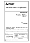
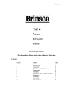
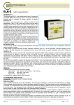
9.
10.
MK330A Self-Reclosing Earth Leakage Relay
User's Manual
RECORDS
a.
b.
c.
Record the 3 latest tripped faults current or “tSt” for manual trip test.
The records are stored in non-volatile memory.
To clear the entire record database:
• Step 1: When the relay is healthy, press [RESET] button to step to most recent trip fault record or [FUNC] digit
shown “A”.
• Step 2: Press [▲] and [▼] buttons simultaneously and hold for 3.5s or the [DATA] show “0”. It will clear the
entire fault records database.
A BRIEF OVERVIEW
TECHNICAL DATA
AUXILIARY SUPPLY
MK330A-230A........................184~276 VAC
MK330A-110A........................94~127 VAC
Rated frequency.....................50Hz or 60Hz
VA Rating...............................3 VA typical
RECORDS
Fault record....................... 3 latest trip fault current or “tSt”
for manual trip test
Storage.............................. Non-volatile memory
SETTING RANGES
Sensitivity adjustment............ 30mA, 50mA,
0.10~1.00A (step=50mA),
1.00~10.0A (step=1.00A)
Delay time adjustment........... Instantaneous,
0.1~3.0s (step=0.1s)
Number of shots.....................0~30 (step=1)
0=Disable reclose function
Dead time...............................1~500sec (step=1sec)
Persistent fault time............... 0~500sec (step=1sec)
0=Disable
Reclaim time.......................... 0~500min (step-1min)
0=Disable
Lockout self reset time........... 0~200hrs (step=1hour)
0=Disable
Programmable contact...........0~6 (step=1)
DIGITAL INPUT PORT
Remote reset..................... N.O. Dry contact
k
e
f
MECHANICAL
Mounting............................Standard DIN 96x96mm panel
mounting
Approximate weight........... 0.58kg (excluding ZCT)
N
L
1
2
3
4
5
6
NC
9
NO
10
8
7
TRIP SAFE
CONTACT*
NC
COM
12
13
14
CONTACTOR
96mm
96mm
FRONT
- Sensitivity setting
- Time time delay setting
SHOTS
tDEAD
- Nos of reclose operations
- Dead time
tPF
- Persistent fault monitoring time
tREC
- Reclaim time
h - TEST button
NO
15
i - Model
COM
j - DP1 indicator
16
k - FUNC display
90mm
70mm
SIDE
1.
91±0.5mm
tLAR
- Lockout auto reset time
RLY2
Flt 1
- Programmable Output contact
- Fault record #1(Most recent)
Flt 2
Flt 3
- Fault record #2
- Fault record #3(Oldest)
DESCRIPTION
The MK330A is microprocessors based earth leakage relay with built in self-reclosing function.
PANEL
CUTOUT
91±0.5mm
CASE DIMENSION
I n
t
g - RESET button
LOAD
12.
Symbols
f - Increment button
The EARTH wire
must not pass
through the ZCT
ALARM
CONTACT
11
a - DATA display
e - Decrement button
MIKRO
ZCT
h
b - Trip status indicator
d - DP2 indicator
PE
MK330A
g
i
c - Alarm status indicator
L1 L2 L3 N
REMOTE
RESET
d
ZERO-PHASE CURRENT TRANSFORMERS
To operate with Mikro's ZCT series of current transformers
CONNECTION DIAGRAM
AUX
c
j
OUTPUT CONTACTS
Contact rating.................... 5A (NO) / 3A (NC) / AC1
Contact arrangement.........Change over
Expected electrical life.......10,000 at rated current
Expected mechanical life...5,000,000 operations
INDICATORS
Pre-fault alarm....................... Red indicator
Leakage trip delay time..........Red indicator
Leakage trip........................... 7-segment display and red indicators
Manual test trip...................... 7-segment display and red indicators
ZCT connection fault..............7-segment display and red indicators
Trip records............................7-segment display
Real-time leakage current......7-segment display
11.
a
b
The earth leakage protection module is designed for measure the low-level current flowing from the live
part of the installation to the earth in the absent of the insulation fault. A zero phase current transformer
is connected to the relay and function as the sensor for sensing the leakage current. All conductors of
the circuit to be protected shall go through the ZCT.
While the self reclosing module provide multiple number of shots operation. It also incorporates
intelligent to differentiate the transient fault or persistent fault.
2.
LIGHT INDICATORS
[Trip]
LED
[Alarm]
LED
0
0
0
0
0
B
0
[DP1]
indicator
[DATA]
display
0
0
0
No auxiliary supply
X
X
1
Normal condition, no tripping
X
X
X
Leakage current > 50% of the I∆n
FB
X
X
X
Leakage current > 85% of the I∆n. Trip delay time running.
1
1
0
0
B
Relay tripped
0
0
1
0
1
Scroll through setting
0
0
1
1
1
Scroll through records
0
0
B
0
1
[DATA] programming mode
1
1
X
X
“Ct”
ZCT connection fault
X
X
X
X
“tSt”
Manual trip test
X
[FUNC]
display
X
X
X
X
X
X
“Loc”
X
“PLo”
Table 1: Relay status displayed
1 = ON
B = Normal blink
3.
• Step 2: Press [▲] and [▼] buttons simultaneously and hold for 1.5s to enter programming mode. The [FUNC]
digit blink to indicate the relay has enter into the programming mode.
• Step 3: Press [▲] or [▼] button to increase or decrease the parameter value.
• Step 4: To save the selected value, press [▲] and [▼] buttons simultaneously and hold for 1.5s. It will exit the
programming mode with [DATA] displaying the new setting.
• To exit programming mode without saving the selected setting, press the [RESET] button once.
Status
4.
DIGITAL INPUT PORT
5.
OUTPUT CONTACTS
a.
b.
The digital port is for remotely reset the relay when tripped, lockout or ZCT connection fault.
To reset the relay, make a connection between terminals 5 and 6 of the relay.
a.
Trip Safe Contact:
• Activated and latch when the relay is in normal power-up condition with the measured leakage current less than
0.85 I∆n. De-activated during leakage trip, manual test trip or ZCT connection fault.
b.
Programmable Contact:
[DATA]
Pre-fault Alarm
Leakage Trip
Manual Test Trip
Re-close Lockout
ZCT Connection Fault
0
X
X
X
X
X
1
√
√
√
√
√
2
X
X
X
X
√
3
X
√
√
√
X
4
X
X
X
√
X
Transient fault lockout by reclose function
Persistent fault lockout by reclose function
0 = OFF
FB = Fast blink
X = Don't care
PUSH BUTTONS OERATION
a.
b.
c.
Integral Trip Test:
• Press the [TEST] button and hold for 3.5s to perform an integral test on the relay ranging from the analog
sensing circuitry to output contacts of the relay as well as the relay indicators and display.
• During the testing process, the first 2s is to simulate the pre-fault alarm condition then follow by 1.5s testing on
the trip time delay. End of time delay, relay trip.
Trip Reset; Lockout Reset and ZCT Connection Fault Reset:
• Press the [RESET] button once or through digital input port.
• ZCT connection fault reset is inhabited if the fault is not rectify
[DP1]
[DP2]
Symbols
√
√
√
X
X
X
X
√
√
Table 3: Programmable contact selection table
X = Disable
√ = Enable
6.
SELF-RECLOSE
Description
Real-time leakage current display (Default)
Description
Shots
Nos of self-reclosing operation before lockout.
Dead time
Time when the trip safe contact de-activated due to leakage fault or manual test trip to the
time when the trip safe contact is activated by the recloser.
Persistent fault
monitoring time
Fault detected immediately after the trip safe contact is activated by the recloser is called
persistent fault. An time frame for monitor the persistent fault is called persistent fault time.
Reclaim time
Time required by the recloser to reset back to initial state since the last reclose operation
Time required for unlock and reset the self-reclosing module during lockout state. The
unlock operation is carry out when no operators attended the relay during lockout state.
Blank
Off
Note 1
1
Off
On
I∆n
Sensitivity setting (A)
Lockout automatic
reset time
2
Off
On
∆t
Trip time delay setting (second)
Transient fault lockout
3
Off
Off
SHOTS
Nos of shots / reclose operations
When the number of self reclosing operations match the number of shots setting, further
fault trip will perform the lockout.
4
Off
Off
tDEAD
Dead time (sec)
Persistent fault lockout
Relay lockout when the tripping is initiated by the persistent fault
5
Off
Off
tPF
Persistent fault monitoring time (sec)
Table 4: Self reclose function explanation
6
Off
Off
tREC
Reclaim time (min)
a) Shots, Dead Time and Reclaim Time
7
Off
Off
tLAR
Lockout automatic reset time (hours)
8
Off
Off
RLY2
Programmable contact
A
On
Note 1
Flt 1
Fault record #1 (Most recent)
b
On
Note 1
Flt 2
Fault record #2
c
On
Note 1
Flt 3
Fault record #3 (Oldest)
Table 2: List of [FUNC] code displayed
Note 1:
If DP2 is OFF. The unit for the [DATA] displayed is in mA.
If DP2 is ON. The unit for the [DATA] displayed is in ampere (A).
d.
√
6
Terms
Parameters Viewing:
• When the relay is operate normal and no tripping, press [RESET] button to step through the various parameters.
• When step through the parameters, press [RESET] button and hold for 1.5 second to jump direct to the default
[FUNC].
[FUNC]
5
Parameters Setting
• Step 1: Press [RESET] button to step to desired parameter.
b)
Persistent Fault Monitoring Time
Leakage
Leakage
Trip Safe
Contact
Trip Safe
Contact
Dead Time
Dead Time
Reclaim
Time
Persistent
Fault
Shots
Counter
0
1
2
0
Lockout