1
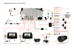
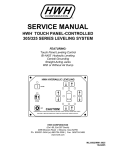
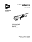
HW H
R
CORPORATION
SERVICE MANUAL
HWH COMPUTER-CONTROLLED
500 SERIES LEVELING SYSTEM
R
FEATURING:
Touch Panel Leveling Control
Four-Point Air Leveling
HWH COMPUTERIZED LEVELING
LEVEL
AIR
EXCESS
SLOPE
NOT IN
PARK/
BRAKE
DUMP
TRAVEL
OFF
RAISE
CAUTION!
UNDERSTAND OPERATOR’S MANUAL BEFORE USING. BLOCK FRAME AND TIRES
SECURELY BEFORE REMOVING TIRES OR CRAWLING UNDER VEHICLE.
HWH CORPORATION
(On I-80, Exit 267 South)
2096 Moscow Road | Moscow, Iowa 52760
Ph: 800/321-3494 (or) 563/724-3396 | Fax: 563/724-3408
www.hwh.com
ML22362/MI91.0019
06MAY04
SECTION 1
N
TIO
SEC
1
E
UBL
O
R
T
TING
O
O
SH
PS
STE
SECTION
2
REPAIR STEPS
SEC
TION
3
DIAG
RAM
S
3 PART FOLDER
HOW TO USE MANUAL
This manual is written in three sections. Section 1 is the Trouble Shooting Steps. Section 2 is the Repair Steps. Section 3 is
the Diagrams. Begin diagnosis of the system with Section 1, the Trouble Shooting Steps. This will give the correct operation
and function of the system. When a malfunction is encountered, the Trouble Shooting Steps will direct you to the proper Repair
Steps in Section 2, the Repair Steps. The Repair Steps are broken into 3 columns, Problem, Solution, and Diagram. In the
proper part under Problems, find the symptom you have encountered. The testing and repair for that problem is in the Solution (center) column. Diagrams for a particular Problem and Solution are in the Diagram (right hand) column. This column will
direct you to the proper diagram in Section 3, Diagrams, for a more detailed view.
Before beginning your repair, it is IMPORTANT to read the CAUTIONS and NOTES AND CHECKS in the first section, TROUBLE
SHOOTING STEPS. In many cases this will save time and mistakes when trouble shooting a system.
This Repair Manual is offered as a guide only. It is impossible to anticipate every problem or combination of problems. This
manual is written in sequential order of the proper operation of the system. The Trouble Shooting Steps must be followed in
order to give correct diagnosis of the problem(s). For any problems encountered that are not addressed in this manual, contact
HWH Corporation for assistance.
NOTE: Diagrams in this manual are of typical systems. There may be plumbing or harness differences. In most cases
this should not effect trouble shooting procedures.
PROCEED WITH TROUBLE SHOOTING GUIDE
MI91.1015
18JUN01
TROUBLE SHOOTING
CAUTIONS!
BLOCK FRAME AND TIRES SECURELY BEFORE CRAWLING UNDER VEHICLE. DO NOT USE AIR SUSPENSION TO SUPPORT VEHICLE WHILE UNDER VEHICLE OR CHANGING TIRES. VEHICLE MAY DROP AND OR
MOVE FORWARD OR BACKWARD WITHOUT WARNING CAUSING INJURY OR DEATH.
DO NOT EXCEED 5 MPH OR TRAVEL LONG DISTANCES WHEN THE SUSPENSION IS NOT AT THE PROPER
RIDE HEIGHT.
SAFETY CLASSES ARE TO BE WORN TO PROTECT EYES FROM DIRT, METAL CHIPS, OIL LEAKS, ETC. FOLLOW
ALL OTHER SHOP SAFETY PRACTICES.
NOTES AND CHECKS
Read and check before preceding with Trouble Shooting Steps.
NOTE: HWH CORPORATION ASSUMES NO LIABILITY
FOR DAMAGES OR INJURIES RESULTING FROM THE
INSTALLATION OR REPAIR OF THIS PRODUCT.
1. The trouble shooting guide must be followed in order. Problems checked for in one step are assumed correct and not
checked again in following steps.
2. Batteries should be in good condition and fully charged. Low
voltage can cause erratic operation.
3. Do not replace the control box unless the repair steps say
to replace it. Otherwise the malfunctions may damage the
new control box.
4. If the control box is removed, +12 ignition power must be
applied to the travel solenoid wires (GRAY) 1700 in the front
and (GRAY) 3700 in the rear air harnesses. This will allow the
height control valve to function. See MP85451F of section (3)
Diagrams.
3 - POINT AIR LEVELING
This manual is intended for use by experienced mechanics
with knowledge of air suspension and automotive electrical
systems. People with little or no experience with HWH
leveling systems should contact HWH technical service
(800-321-3494) before beginning. Special attention should
be given to all cautions, wiring, and air diagrams.
Special note: When installing a new control box, make
sure the box is properly grounded before applying power
to the system.
Suggested tools for trouble shooting the HWH leveling systems:
JUMPER WIRES(UP TO 10 GAUGE)
MULTI-METER
12 VOLT TEST LIGHT
PROCEED WITH THE TROUBLE
SHOOTING STEPS ON THE
FOLLOWING PAGE
This manual can be used to diagnose problems with older
3 - Point Air Leveling systems. The difference is the front
manual buttons control only one solenoid valve. The side
manual buttons control only the left rear or right rear solenoid
valves. There is only one front travel solenoid valve. Side to
side leveling is accomplished using only the rear air bags.
There are no pressure switches used on 3 - Point Air Leveling
systems.
MI91.101J
28APR00
CONTROL IDENTIFICATION
"EXCESS SLOPE"
Indicator light
"TRAVEL"
Indicator light
"NOT IN PARK"
Indicator light
AIR OPERATION
Indicator light
LOWER FRONT
Manual Button
RAISE FRONT
Manual button
"AIR" BUTTON
HWH COMPUTERIZED LEVELING
AIR DUMP
Indicator light
LEVEL
"DUMP" BUTTON
AIR
AIR BAG
Indicator light
(4 red)
RAISE RIGHT SIDE
Manual button
NOT IN
PARK/
BRAKE
DUMP
RAISE
Indicator light
EXCESS
SLOPE
LOWER RIGHT SIDE
Manual button
TRAVEL
OFF
RAISE
CAUTION!
UNDERSTAND OPERATOR’S MANUAL BEFORE USING. BLOCK FRAME AND TIRES
SECURELY BEFORE REMOVING TIRES OR CRAWLING UNDER VEHICLE.
"OFF" BUTTON
LEVEL SENSING
Indicator light
(4 yellow)
RAISE REAR
Manual button
"RAISE"
Button
RAISE LEFT SIDE
Manual button
LOWER LEFT SIDE
Manual button
LOWER REAR
Manual button
CONTROL FUNCTIONS
CONTROL BUTTONS
"AIR" Button - This button is the system on button and automatic
operation button.
"EXCESS SLOPE" light - This light will be on if the leveling
system can NOT level the coach.
"OFF" Button - This button will turn the system OFF but does
NOT control power to the "DUMP" or "RAISE" buttons.
"TRAVEL" light - This light will be on if the leveling system is off
and the coach suspension is operable.
"DUMP" Button - This button will lower the whole coach by
dumping air from the suspension system.
AIR BAG lights- These lights will be on when the system is on
if the ignition is on, or if the ignition is on and an air bag has
low air pressure, that individual red warning light will be on. The
coach should NOT be moved while these lights are on.
"RAISE" Button - This button will raise the whole coach
by adding air to the suspension system.
UP ARROWS - These are the RAISE manual buttons.
DOWN ARROWS - These are the LOWER manual buttons.
LEVEL SENSING lights- One or two yellow lights can be on
indicating that side or end of the coach is low.
"NOT IN PARK/BRAKE" light- This light will be on if the "AIR"
button is pushed and the park brake is not set.
INDICATOR LIGHTS
AIR OPERATION light - This light will be on when the system
is on, and flash during automatic leveling.
AIR DUMP light - This light will flash when the "DUMP" button
is being pushed.
RAISE light - This light will flash when the "RAISE" button
is being pushed.
MI91.102J
26APR00
TROUBLE SHOOTING STEPS
NOTE: The coach should be at the proper ride height before
starting the Trouble Shooting Steps.
1. Make sure the transmission is in the recommended position
for parking and the park brake is set. The ignition switch should
be in the "OFF" position. If any touch panel lights are on, see
Part 1 of the Repair Steps.
AUTOMATIC LEVELING
6. Start the coach engine. Set the park brake. Push the "AIR"
button one time to turn the system on. Push the "AIR" button
a second time. This will start automatic leveling. The following
should occur:
a.
b.
2. Turn the ignition switch to "ON". Only the green "TRAVEL" c.
light should be lit. If this is not so, see Part 2 of the Repair Steps. d.
3. Press the "AIR" button one time. The "ON" indicator light
should come on. One or two yellow level indicator lights may
come on. The four red AIR BAG indicator lights and the Master
Warning Light should be on. The "TRAVEL" light should NOT
be on. If this is not correct see Part 3 of the Repair Steps.
4. MANUAL OPERATION:With the system on, the manual up
and down arrows should function. These buttons are momentary buttons. Releasing the button will stop the function. Each
set of arrows operate pairs of air bags, front, rear, or sides.
There are two air manifolds. One for the front air bags and one
for the rear air bags. Each manifold has six air solenoid valves.
A right and left raise valve, a right and left lower valve and a
right and left travel valve. (See MP85.3535). The travel solenoids are tied together electrically in the harnesses and should
be on if the ignition is in the "ON" position and the system is
off. The manifolds have a right and left air pressure switch.
When the pressure in one air bag drops to approximately
20 psi, the pressure switch for that bag completes a ground signal for the control box. This will turn the appropriate red warning
light and the master warning light on if the ignition is on and the
leveling system is off. The pressure switches do not inhibit any
leveling procedures. When an up arrow is pushed a +12 signal
is sent to the auxiliary air compressor and the corresponding
raise solenoid on the air manifolds. The raise valves open the
air bags to inflate lifting the coach. The air compressor will only
run as the system pressure drops.
When a down arrow is pushed a +12 signal is sent to the corresponding lower solenoids. The lower valves will open allowing the air bags to deflate lowering the coach.
Test each set of up and down arrows checking that the appropriate air bags will inflate and deflate and that the auxiliary
compressor will run during the raise function. If there is any
malfunction see Part 4 of the REPAIR STEPS.
5. SENSING UNIT CHECK: Using a bubble level inside the
coach, level the coach using the up and down arrow buttons.
All yellow indicator lights should be off at this time. If not, the
sensing unit may need to be adjusted. A yellow light indicates
that side or end of the coach is low. Check that all yellow lights
can be made to come on (at different times) by raising and /or
lowering the ends and sides of the coach. If the ground is too
uneven the coach may need to be moved to complete this test.
For sensor adjustment procedure see MP85.9505.
For sensor testing see Part 5 of the REPAIR STEPS.
The four red warning lights will be on.
The indicator light above the "AIR" button will start to flash.
The master warning light will be on.
The coach will automatically level itself. The leveling procedure is as follows:
If there are no yellow lights the control box will go directly
into a sleep mode.
If there are yellow lights on, leveling will start in a down
mode, deflating air bags opposite to lit yellow level indicator lights. After 2 minutes if the coach is not level, the computer will switch to the "UP" mode, inflating air bags according to lit yellow lights. During any raise (UP) function
the compressor may run. When all the yellow lights are
are out, the control box goes into the sleep mode.
SLEEP MODE: After leveling the coach the control box
will remain on but inactive for 30 minutes. After 30 minutes
the control box will wake up and monitor the yellow lights
until leveling is needed. If a light is on or comes on and
remains on for 60 seconds, the control box will relevel the
coach using the original leveling procedure. After leveling
the vehicle the control box will return to the sleep mode.
EXCESS SLOPE: During the leveling mode, either initially or after a sleep mode, if the coach cannot be leveled
in 10 minutes after the system starts leveling in the raise
mode, the control box will stop all operations, and the
"EXCESS SLOPE" indicator will come on. The box will
remain on until the "OFF" button is pushed, but will not go
into a sleep mode. If the system reached 15 minutes of
accumulative time before the 10 minutes EXCESS SLOPE
time, the system will go to the SLEEP MODE even though
a yellow LEVEL light may be on.
If any of the above does not occur, see Part 6 of the
REPAIR STEPS.
7. TRAVEL MODE: With the ignition on and leveling system
off, the coach should return to the proper travel height. The
travel solenoids are energized allowing the height control valves
to function. If the coach will not return to the proper ride height
see Part 7 of the REPAIR STEPS.
8. DUMP AND RAISE BUTTONS The "DUMP" AND "RAISE"
buttons are for operator convenience. They allow the coach to
temporarily be raised or lowered to clear obstacles while moving. These are momentary buttons. When released, the coach
will return to ride height if the ignition is on. These buttons will
operate with the system on or off, and the ignition on or off. If the
system is on, the system will turn off when the button is released.
The "DUMP" and "RAISE" button will lower or raise the whole
From this point on, it is assumed the system is fully funccoach. If they are not working correctly see Part 8 of the REPAIR
tional in the manual mode. Whenever a malfunction occurs, STEPS.
revert to the manual operation and check for correct funcDo not exceed 5 mph or travel long distioning. If a problem is found in manual operation, trouble
tances when using these buttons or if the coach is not at
shoot the problem using the preceding steps. Remember,
low volts can cause erratic performance and damage com- the proper travel height.
ponents.
CAUTION:
MI91.103J
26APR00
SECTION 2
500 SERIES
REPAIR MANUAL
HWH COMPUTER-CONTROLED
LEVELING SYSTEM
TOUCH PANEL CONTROL
4 - POINT AIR LEVELING
BEGIN WITH SECTION 1
MI91.2013
07MAR01
REPAIR STEPS
PROBLEM
SOLUTION
Part 1
Touch panel has
indicator lights on
with the ignition
switch off.
If the "ON" indicator light is on, press the "OFF" button. If the "ON"
light or any other light remains on, replace the control box. If the
"ON" light is not on and any other light is on, replace the control box.
FIGURES
AIR OPERATION
indicator light
HWH COMPUTERIZED LEVELING
LEVEL
TRAVEL
OFF
RAISE
CAUTION!
UNDERSTAND OPERATOR’S MANUAL BEFORE USING. BLOCK FRAME AND TIRES
SECURELY BEFORE REMOVING TIRES OR CRAWLING UNDER VEHICLE.
REFER TO MI91.102J
OF SECTION I
HWH COMPUTERIZED LEVELING
LEVEL
AIR
NOT IN
PARK/
BRAKE
DUMP
TRAVEL
OFF
RAISE
CAUTION!
UNDERSTAND OPERATOR’S MANUAL BEFORE USING. BLOCK FRAME AND TIRES
SECURELY BEFORE REMOVING TIRES OR CRAWLING UNDER VEHICLE.
(BLACK) 1210
1
2
5
(ORANGE) 2210 3
4
(BLUE) 4210
(YELLOW) 3210 5
15
5
15
15
WARNING LIGHT
CONTROL (PURPLE) 7699
40PIN
CONNECTOR
NOTE: If the vehicle is not equipped
with a master warning light, proceed to
Part 2b.
RED REAR
GREEN RIGHT SIDE
BLACK FRONT
YELLOW LEFT SIDE
WHITE (GROUND)
6
SENSING
UNIT
7
8
9
10
5
5
5
5
5
11
5
12
7.5
13
14
5
5
5
PUMP/MS
HARNESS
15
BATTERY - (RED) 6100
IGNITION - (YELLOW) 6110
ACCESSORY - (BROWN) 6120
COMPRESSOR
AIR BAG PRESSURE
SWITCH SENSORS
FROM FRONT AND
REAR AIR HARNESS
MASTER
WARN
LIGHT
O.E.M. REMOTE
INDICATORS
FRONT
AIR
PARK
POWER
HARNESS HARNESS BRAKE
REFER TO MI91.102J
OF SECTION I
REAR AIR
HARNESS
Whenever the ignition switch is "ON" one of these lights will be lit
but never both at the same time. If neither light is on, check the
power to the control box. The (YELLOW) 6110 wire in the power harness will have +12 volts with the ignition in the "ON" position. The (RED)
6100 wire should have +12 volts with the ignition in any position. If the
(YELLOW) 6110 wire has power replace the control box. If not, trace
the (YELLOW) 6110 wire to its source.
EXCESS
SLOPE
16
15
17
18
15
*ATTACH #10 WIRE
FROM PUMP HARNESS
(BLACK) 6800
19
20
21
15
HYDRAULIC
HARNESS
a. The green
"TRAVEL" light nor
the master warning
light is lit.
EXCESS
SLOPE
NOT IN
PARK/
BRAKE
DUMP
"OFF" BUTTON
"TRAVEL"
indicator light
Part 2
With the ignition
switch on:
AIR
15
15
15
REFER TO MP85.3530
REFER TO MP75.4555
PRESSURE
SWITCH
(BLACK) 1210
1
2
5
(ORANGE) 2210 3
4
(BLUE) 4210
(YELLOW) 3210 5
15
5
15
15
WARNING LIGHT
CONTROL (PURPLE) 7699
40PIN
CONNECTOR
RED REAR
GREEN RIGHT SIDE
BLACK FRONT
YELLOW LEFT SIDE
WHITE (GROUND)
6
SENSING
UNIT
7
8
9
10
5
5
5
5
5
11
5
12
7.5
13
14
LF RAISE - (GREEN) 1500
LF LOWER - (RED) 1600
FRONT TRAVEL - (GRAY) 1700
RF LOWER - (BLUE) 2600
RF RAISE - (YELLOW) 2500
COMPRESSOR
AIR BAG PRESSURE
SWITCH SENSORS
FROM FRONT AND
REAR AIR HARNESS
MASTER
WARN
LIGHT
O.E.M. REMOTE
INDICATORS
FRONT
AIR
PARK
POWER
HARNESS HARNESS BRAKE
REFER TO MP75.4555
REAR AIR
HARNESS
There are two pressure switches on each manifold. Unplug the switch
corresponding to the lit red warning light. If the warning light goes out,
replace the pressure switch. If the light does not go out, unplug the
appropriate harness from the control box. If the light goes out, the
pressure switch wire is shorted to ground. If the light does not go out,
the problem is the control box or the ribbon cable.
PRESSURE
SWITCH
LF RAISE - (GREEN) 4500
LR LOWER - (PURPLE) 4600
REAR TRAVEL SOL. - (GRAY) 3700
RR LOWER - (BROWN) 3600
RR RAISE - (ORANGE) 3500
5
5
15
5
16
15
17
18
15
PUMP/MS
HARNESS
With the system off and the ignition in the "ON" position, the master
warning light will come on and the "TRAVEL" light will go out if an air
bag has low pressure. The corresponding red warning light will be on.
If the coach is not at the proper ride height start the coach engine
and build up air pressure. Make sure there is 20+ psi in all air bags.
The master warning light should go out and the "TRAVEL" light should
come on as the coach returns to the proper ride height. If the coach
will not return to the proper travel height see Section 7 of the TROUBLE SHOOTING STEPS. If the master warning light is lit, the "TRAVEL" light is not on, and the coach is at the proper ride height there
is a bad pressure switch or a shorted pressure switch wire for the red
warning light that is lit.
*ATTACH #10 WIRE
FROM PUMP HARNESS
(BLACK) 6800
19
20
21
15
HYDRAULIC
HARNESS
b. The master
warning light is lit
and/or the "travel"
light is not lit. One
or more red warniing lights on the
touch panel is lit.
15
15
15
REFER TO MP85.3530
MI91.202J
26APR00
REPAIR STEPS
SOLUTION
O.E.M. REMOTE
INDICATORS
(BLACK) 1210
1
2
5
(ORANGE) 2210 3
4
(BLUE) 4210
(YELLOW) 3210 5
15
5
15
15
40PIN
CONNECTOR
RED REAR
GREEN RIGHT SIDE
BLACK FRONT
YELLOW LEFT SIDE
WHITE (GROUND)
Check the battery fuse. If it is not blown the control box, touch panel,
or cable is bad. If the battery fuse is blown, replace the fuse, unplug
the compressor wire then press the "AIR" button again. If the fuse
blows again replace the control box. If the fuse does not blow and
the system turns on, the compressor wire is probably shorted to
ground.
b. All of the panel
lights come on and
stay on.
The microprocessor is bad. Replace the control box. It also could
be a bad touch panel.
6
5
7
8
5
5
9
10
PART & SERIAL
NUMBER STICKER
5
COMPRESSOR - (BROWN) 9700
5
11
5
12
7.5
13
14
5
5
15
5
16
15
17
18
15
PUMP/MS
HARNESS
a. The system will
not turn on and no
lights except the
TRAVEL light are
on.
SENSING
UNIT
REAR AIR
HARNESS
WARNING LIGHT
CONTROL (PURPLE) 7699
FRONT
AIR
PARK
POWER
HARNESS HARNESS BRAKE
AIR BAG PRESSURE
SWITCH SENSORS
FROM FRONT AND
REAR AIR HARNESS
MASTER
WARN
LIGHT
Part 3
After pushing the
"AIR" button one
time:
COMPRESSOR
DIAGRAMS
ESSEX RELAY MOUNTED
ON INSIDE OF BOX
15
*ATTACH #10 WIRE
FROM PUMP HARNESS
(BLACK) 6800
19
20
21
HYDRAULIC
HARNESS
PROBLEM
15
15
15
REFER TO MP85.3530
TOUCH PANEL
SEE CONTROL BOX
CONNECTION DIAGRAM
RIBBON
CABLE
COMPUTERIZED LEVELING
AIR
EXCESS
SLOPE
LEVEL
(YELLOW) 3210
NOT IN
PARK/
BRAKE
AB
DUMP
c. The on indicator
light will not stay on
and the NOT IN
PARK/BRAKE light
comes on while the
"AIR" button is being pushed.
Make sure the park brake is set. Check for a ground on the (BLUE)
9000 Park/Brake Sensor wire. If a ground is present, replace the control box. If a ground is not present trace the (BLUE) 9000 wire and
check its connection. Check the park brake switch.
#10 GROUND
WIRE TO
FRAME
TO BRAKE
LIGHT ON DASH
(BLUE)
4210
GROUND
STUD
TRAVEL
OFF
RAISE
CAUTION!
UNDERSTAND OPERATOR’S MANUAL BEFORE USING. BLOCK FRAME AND TIRES
SECURELY BEFORE REMOVING TIRES OR CRAWLING UNDER VEHICLE.
PARK BRAKE
SWITCH - 9000
6258
6254
PARK BRAKE
PIGTAIL (BLUE) 9000
POWER
HARNESS
5
15
15
6
5
7
8
5
40PIN
CONNECTOR
RED REAR
GREEN RIGHT SIDE
BLACK FRONT
YELLOW LEFT SIDE
WHITE (GROUND)
SENSING
UNIT
5
15
5
9
10
PART & SERIAL
NUMBER STICKER
5
FRONT
AIR
PARK
POWER
HARNESS HARNESS BRAKE
1
2
3
4
5
REAR AIR
HARNESS
O.E.M. REMOTE
INDICATORS
5
11
5
12
7.5
13
14
5
15
5
16
15
17
18
15
5
PUMP/MS
HARNESS
Unplug the sensing unit cable. There are five pins. The pin for the
white wire is the ground for the sensing unit. The other four pins are
for the front, rear, left and right side yellow lights. Ground each individual pin. Only one light should come on per pin. If more than one
light comes on, replace the control box. If only one light comes on,
replace the sensing unit.
ESSEX RELAY MOUNTED
ON INSIDE OF BOX
15
*ATTACH #10 WIRE
FROM PUMP HARNESS
(BLACK) 6800
19
20
21
HYDRAULIC
HARNESS
d. Opposite yellow
lights come on.
COMPRESSOR
REFER TO MP85.3535
15
15
15
REFER TO MP85.3530
"TRAVEL"
indicator light
e. With the "ON"
indicator light lit, the
TRAVEL light will
not go out.
The travel light should not be on when the system is on. Replace
the control box.
AIR OPERATION
indicator light
HWH COMPUTERIZED LEVELING
LEVEL
AIR
EXCESS
SLOPE
NOT IN
PARK/
BRAKE
DUMP
TRAVEL
OFF
RAISE
CAUTION!
UNDERSTAND OPERATOR’S MANUAL BEFORE USING. BLOCK FRAME AND TIRES
SECURELY BEFORE REMOVING TIRES OR CRAWLING UNDER VEHICLE.
5
3
15
15
5
15
6
7
8
9
10
PART & SERIAL
NUMBER STICKER
FRONT
AIR
PARK
POWER
HARNESS HARNESS BRAKE
1
2
4
5
WARNING LIGHT
CONTROL (PURPLE) 7699
5
5
5
5
REAR AIR
HARNESS
O.E.M. REMOTE
INDICATORS
5
11
5
12
7.5
13
14
5
5
15
5
16
15
17
18
15
PUMP/MS
HARNESS
The (PURPLE) 7699 wire from the master warning indicator output
should be a ground when the the system is on and the ignition is in the
"ON" position. If not, replace the control box. If ground is present, check
the (PURPLE) 7699 wire at the light. Check the +12 power for the light
or replace the bulb.
ESSEX RELAY MOUNTED
ON INSIDE OF BOX
*ATTACH #10 WIRE
FROM PUMP HARNESS
(BLACK) 6800
19
20
21
15
HYDRAULIC
HARNESS
f. The master
warning light is
not on.
COMPRESSOR
REFER TO MI91.102J
OF SECTION I
15
15
15
REFER TO MP85.3530
MI91.202P
28APR00
REPAIR STEPS
Check that the exhaust ports af the air manifolds are not plugged.
Check the fuse for the appropriate lower solenoid valve. If the fuse is
blown the solenoid valve is bad or the power wire for the solenoid
valve shorted.
RAISE SOLENOID
VALVE (2) RIGHT & LEFT
AIR BAG PRESSURE
SWITCH SENSORS
FROM FRONT AND
REAR AIR HARNESS
MASTER
WARN
LIGHT
O.E.M. REMOTE
INDICATORS
(BLACK) 1210
1
2
5
(ORANGE) 2210 3
4
(BLUE) 4210
(YELLOW) 3210 5
15
5
15
15
WARNING LIGHT
CONTROL (PURPLE) 7699
40PIN
CONNECTOR
RED REAR
GREEN RIGHT SIDE
BLACK FRONT
YELLOW LEFT SIDE
WHITE (GROUND)
6
SENSING
UNIT
7
8
9
10
PART & SERIAL
NUMBER STICKER
FRONT
AIR
PARK
POWER
HARNESS HARNESS BRAKE
REFER TO MP75.4555
5
5
5
5
COMPRESSOR
If the fuse is not blown check for power on the corresponding pin in
the control box. If power is not present, replace the control box. If
power is present on the pin, the problem is the wire to the valve,
the ground for the valve, or the valve. Check for power in the harness plug. If it is a 2 - wire plug check between the two pins in the
plug. If it is a 1 - wire plug check between the plug and ground. If
power is present check the ground for the solenoid if it is a 1 - wire
plug. Replace the valve if power is present and the ground is OK. If
power is not present a wire or connection is bad. If a 2-wire plug is
used the white wire is ground. Check for power between the (colored)
black wire and a frame member. If power is present repair the ground
wire. If power is not present repair the (colored) black wire.
REAR AIR
HARNESS
NOTE: The coach
should be at proper
ride height when
testing down arrows.
DIAGRAMS
5
11
5
12
7.5
13
14
5
5
15
5
16
15
17
18
15
PUMP/MS
HARNESS
Part 4
When pushing an
up or down arrow:
a. An air bag will
not deflate when
pushing a LOWER
maunual button
(down arrow).
SOLUTION
ESSEX RELAY MOUNTED
ON INSIDE OF BOX
*ATTACH #10 WIRE
FROM PUMP HARNESS
(BLACK) 6800
19
20
21
15
HYDRAULIC
HARNESS
PROBLEM
15
15
15
GROUND STUD MOUNTED
ON SIDE OF BOX
GROUND #10 WIRE
TO FRAME RAIL
6254
6258
GROUND WIRES
FROM FRONT &
REAR AIR HARNESS
REFER TO MP85.3530
b. Diagonal air
bags deflate or inflate when a side
manual button
(up or down arrow)
is pushed.
c. Air bags will not
inflate when a
RAISE manual
button (up arrow)
is pushed.
If diagonal bags such as left front and right rear deflate or inflate
when a side arrow is pushed the wiring or plumbing connection are
switched. Check the diagrams and redo connections according to
the diagrams.
REFER TO MP75.3520
OR 75.3530
REFER TO MP85.3535
Check the appropriate fuse for that raise solenoid valve. If the fuse
is blown the valve, or the power wire to the valve is shorted.
If the fuse is not blown check for power on the corresponding pin in
the control box. If power is not present, replace the control box. If
power is present on the pin, the problem is the wire to the valve,
the ground for the valve, or the valve. Check for power in the harness plug. If it is a 2 - wire plug check between the two pins in the
plug. If it is a 1 - wire plug check between the plug and ground. If
power is present check the ground for the solenoid if it is a 1 - wire
plug. Replace the valve if power is present and the ground is OK. If
power is not present a wire or connection is bad. If a 2-wire plug is
used the white wire is ground. Check for power between the (colored)
black wire and a frame member. If power is present repair the ground
wire. If power is not present repair the (colored) black wire.
RAISE SOLENOID
VALVE (2) RIGHT & LEFT
REFER TO MP75.4555
GROUND STUD MOUNTED
ON SIDE OF BOX
GROUND #10 WIRE
TO FRAME RAIL
6254
6258
GROUND WIRES
FROM FRONT &
REAR AIR HARNESS
REFER TO MP85.3530
MI91.204J
28APR00
REPAIR STEPS
PROBLEM
SOLUTION
DIAGRAMS
Check the corresponding pin in the box. If +12 is not present replace
the control box.
NOTE: There is no fuse for the compressor wire. The power comes
from the battery fuse in the control box. If the battery fuse is blown
the system will not turn on.
If +12 compressor power is present at the control box, check for
power at the compressor. The compressor harness plug (A) should
have +12 power when an up arrow is pushed. If not the wire is bad.
If power is present check the +12 battery power (B) at terminal 1 of
the 12 volt relay (C) on the compressor assembly. That wire should
be fused. If there is no power check the fuse, the wire, the connections and the source. If there is power to the relay and the compressor will not run, the problem is the pressure switch (D), the relay (C)
or the compressor motor (E).
(BLACK) 1210
1
2
FRONT
AIR
PARK
POWER
HARNESS HARNESS BRAKE
O.E.M. REMOTE
INDICATORS
5
5
(ORANGE) 2210 3
4
(BLUE) 4210
(YELLOW) 3210 5
15
15
15
40PIN
CONNECTOR
RED REAR
GREEN RIGHT SIDE
BLACK FRONT
YELLOW LEFT SIDE
WHITE (GROUND)
SENSING
UNIT
6
5
7
8
5
5
9
10
5
COMPRESSOR - (BROWN) 9700
5
11
5
12
7.5
13
14
5
PART & SERIAL
NUMBER STICKER
REAR AIR
HARNESS
WARNING LIGHT
CONTROL (PURPLE) 7699
5
15
5
16
15
17
18
15
PUMP/MS
HARNESS
NOTE: If the air
system is fully pressurized, the compressor should not
run. Pumping the
brake pedal several times will reduce pressure in
the system allowing the compressor to run.
AIR BAG PRESSURE
SWITCH SENSORS
FROM FRONT AND
REAR AIR HARNESS
MASTER
WARN
LIGHT
The 9700 wire for the air compressor is in the rear air manifold
harness. It goes to the 3 pin compressor plug in the box. When an up
arrow is pushed, there should be +12 power on this wire.
ESSEX RELAY MOUNTED
ON INSIDE OF BOX
HYDRAULIC
HARNESS
d. The compressor will not run
when pushing up
arrows.
COMPRESSOR
Part 4
continued
15
*ATTACH #10 WIRE
FROM PUMP HARNESS
(BLACK) 6800
19
20
21
15
15
15
REFER TO MP85.3530
GRAY FROM
AIR SOLENOID
FUSE
15 AMP
12 VOLT RELAY (2)
+12 SIGNAL FROM
PRESSURE SWITCH
TO +12 BATT
POWER
GROUND
CHECK VALVE (4)
AIR LINE TO SUSPENSION
FLOW
PRESSURE SWITCH (1)
NORMALLY CLOSED
(OPEN AT 115 P.S.I.)
(CLOSED AT 105 P.S.I.)
AIR FILTER
Jump power from terminal 1 to Terminal 2. If the compressor does
not run, check the ground connections at terminal 7. If OK the compressor should be replaced. If the compressor does run, jump
power from terminal 1 to terminal 3, If the compressor does not run
check the ground for terminal 4. If OK, replace the relay (C). If the
compressor runs, check for power at Terminal 5. If power is not present, the short brown lead (F) or the connection to the compressor
harness (A) is bad. If power is present, replace the pressure switch.
(D).
NORMALLY OPEN AIR SOLENOID (3)
GROUND TO RELAY MOUNTING BOLT
BLACK-COMPRESSOR HARNESS FROM CONTROL BOX
REFER TO MP75.4525
COMPRESSOR
HARNESS FROM
CONTROL BOX
BLACK (+12 SIGNAL)
(A)
PRESSURE SWITCH (D)
OPEN 115 PSI
CLOSE 105 PSI
6
WHITE
GROUND
5
BROWN +12 (F)
ORANGE
3
4
12 VOLT
ESSEX
RELAY
(C)
7
BLACK ( GROUND )
1
RELAY MTG. BOLT
RED +12
2
COMPRESSOR MOTOR
(E)
FUSE
15 AMP
(B)
GRAY (GROUND)
GRAY (+12 SIGNAL)
RED
NORMALLY OPEN
12 VOLT AIR SOLENOID
+12 VOLT
BATTERY POWER
1
2
5
(ORANGE) 2210 3
4
(BLUE) 4210
(YELLOW) 3210 5
15
5
15
15
WARNING LIGHT
CONTROL (PURPLE) 7699
40PIN
CONNECTOR
RED REAR
GREEN RIGHT SIDE
BLACK FRONT
YELLOW LEFT SIDE
WHITE (GROUND)
SENSING
UNIT
6
5
7
8
5
9
10
PART & SERIAL
NUMBER STICKER
5
5
5
11
5
12
7.5
13
14
5
15
5
5
ESSEX RELAY MOUNTED
ON INSIDE OF BOX
16
15
17
18
15
*ATTACH #10 WIRE
FROM PUMP HARNESS
(BLACK) 6800
19
20
21
Check that the sensing unit is mounted correctly according to the
sticker on the sensing unit.
FRONT
AIR
PARK
POWER
HARNESS HARNESS BRAKE
(BLACK) 1210
REAR AIR
HARNESS
AIR BAG PRESSURE
SWITCH SENSORS
FROM FRONT AND
REAR AIR HARNESS
MASTER
WARN
LIGHT
O.E.M. REMOTE
INDICATORS
PUMP/MS
HARNESS
Unplug the sensing unit from the control box. Connect the test light
to +12. The pin for the white wire of the sensing unit is a ground.
Check the pin with the test light. If a ground is not present, replace
the control box, If ground is present, connect the test light to ground.
Touch the four pins for the color coded wire. Each pin will light one
yellow light. If this is so, the problem is the sensing unit. If not, replace the control box.
15
HYDRAULIC
HARNESS
Part 5
Yellow level indicator lights, will
not work properly.
COMPRESSOR
REFER TO MP85.4525
15
15
15
GROUND STUD MOUNTED
ON SIDE OF BOX
GROUND #10 WIRE
TO FRAME RAIL
6254
6258
GROUND WIRES
FROM FRONT &
REAR AIR HARNESS
REFER TO MP85.3530
REAR
CROSS MTG (BI-AXIS) SENSING UNIT
THIS
SIDE
UP
REFER TO MP85.9505
MI91.205P
01MAY00
REPAIR STEPS
PROBLEM
SOLUTION
DIAGRAMS
AUTOMATIC LEVELING
If the fuse is not blown, check the corresponding pins in the control
box for the travel solenoids. If +12 power is not present, replace the
control box. If power is present check for power at the manifolds.
Then replace the solenoid valve for any bag that will not reinflate.
1
2
5
(ORANGE) 2210 3
4
(BLUE) 4210
(YELLOW) 3210 5
15
5
15
15
WARNING LIGHT
CONTROL (PURPLE) 7699
40PIN
CONNECTOR
RED REAR
GREEN RIGHT SIDE
BLACK FRONT
YELLOW LEFT SIDE
WHITE (GROUND)
SENSING
UNIT
PART & SERIAL
NUMBER STICKER
6
5
7
8
5
9
10
5
11
5
12
7.5
13
14
5
15
5
5
FRONT
AIR
PARK
POWER
HARNESS HARNESS BRAKE
(BLACK) 1210
5
PARK BRAKE SENS. - (BLUE) 9000
LF RAISE - (GREEN) 1500
LF LOWER - (RED) 1600
FRONT TRAVEL - (GRAY) 1700
RF LOWER - (BLUE) 2600
RF RAISE - (YELLOW) 2500
BATTERY - (RED) 6100
COMPRESSOR
Check the fuse for the travel solenoids. A blown fuse indicates a
shorted wire or solenoid valve. Unplug one air harness at a time to
determine which wire or manifold is shorted. Then unplug the travel
solenoid to determine a bad wire or valve.
REAR AIR
HARNESS
AIR BAG PRESSURE
SWITCH SENSORS
FROM FRONT AND
REAR AIR HARNESS
MASTER
WARN
LIGHT
O.E.M. REMOTE
INDICATORS
IGNITION - (YELLOW) 6110
ACCESSORY - (BROWN) 6120
COMPRESSOR - (BROWN) 9700
LF RAISE - (GREEN) 4500
LR LOWER - (PURPLE) 4600
REAR TRAVEL SOL. - (GRAY) 3700
RR LOWER - (BROWN) 3600
RR RAISE - (ORANGE) 3500
5
PUMP/MS
HARNESS
Part 7
The coach will not
return to the proper travel height
with the ignition
on and the system
off.
If the system will not function properly in the automatic mode, check
steps 1 thru 5. If the system works manually, replace the control box.
Remember low voltage situations and poor ground connections will
cause erratic leveling.
ESSEX RELAY MOUNTED
ON INSIDE OF BOX
16
15
17
18
15
*ATTACH #10 WIRE
FROM PUMP HARNESS
(BLACK) 6800
19
20
21
15
HYDRAULIC
HARNESS
Part 6
After pushing the
"AIR" button twice
the system will not
level properly.
15
15
15
REFER TO MP85.3530
Note: A bad height control valve can cause a ride height problem.
If replacing a travel solenoid valve does not fix the problem, check
for correct operation of the height control valve.
TRAVEL SOLENOID
VALVE (2) RIGHT & LEFT
REFER TO MP75.4555
Part 8
The coach will not
raise or lower
when using the
"RAISE" and
"DUMP" button.
The coach will not
return to travel
height when the
button is released.
These buttons are extensions of the up and down arrows. Check
Part 4 a, b, and d of this section. If these function properly replace
the control box or touch pad.
Recheck Part 7 of this section. If it is OK there may be a problem
with the height control valves.
MI91.206J
27APR00
AIR LINE CONNECTION DIAGRAM
NEWAY
SEE
WATER TRAP
ASSEMBLY
DIAGRAM
FRONT MANIFOLD
PROTECTION
VALVE
TO SUSPENSION
FRONT
AIR TANK
C
AIR BAG
V
REAR MANIFOLD
LINE FROM HEIGHT
CONTROL VALVE
EXISTING AIR LINE
LINE TO AIR BAGS
AIR SUPPLY
C
C
V
V
HEIGHT CONTROL
VALVE (3-PLACES)
MANIFOLDS ARE MOUNTED TO MAIN
CROSS MEMBERS. LEAVE AMPLE
CLEARANCE FOR CONNECTION OF
HOSES TO FITTINGS.
MP75.3520
27APR00
AIR LEVEL SCHEMATIC - NEWAY
4-POINT LEVELING WITH WATER TRAP
PRESSURE SWITCHES FRONT AND REAR
SEE
WATER TRAP
ASSEMBLY
DIAGRAM
PROTECTION
VALVE
AIR
TANK
EXH
FRONT HEIGHT
CONTROL VALVE
(HCV)
FRONT MANIFOLD ASSEMBLY
TRAV.
TRAV.
EXH
AIR
BAG
EXH
LOWER
RAISE
LOWER
AIR
BAG
RAISE
REAR MANIFOLD ASSEMBLY
EXH
EXH
TRAV.
LR HCV
TRAV.
EXH
AIR
BAG
RR HCV
EXH
LOWER
RAISE
LOWER
AIR
BAG
RAISE
MP75.3525
27APR00
AIR LINE CONNECTION DIAGRAM
REYCO
SEE
WATER TRAP
ASSEMBLY
DIAGRAM
PROTECTION
VALVE
FRONT MANIFOLD
TO SUSPENSION
FRONT
AIR TANK
C
AIR BAG
C
V
V
REAR MANIFOLD
LINE FROM HEIGHT
CONTROL VALVE
EXISTING AIR LINE
LINE TO AIR BAGS
AIR SUPPLY
C
V
HEIGHT CONTROL
VALVE (3 PLACES)
MANIFOLDS ARE MOUNTED TO MAIN
CROSS MEMBERS. LEAVE AMPLE
CLEARANCE FOR CONNECTION OF
HOSES TO FITTINGS.
MP75.3530
27APR00
AIR LEVEL SCHEMATIC-REYCO
4-POINT LEVELING WITH WATER TRAP
PRESSURE SWITCHES FRONT AND REAR
AIR
TANK
SEE
WATER TRAP
ASSEMBLY
DIAGRAM
PROTECTION
VALVE
REAR MANIFOLD ASSEMBLY
EXH
EXH
TRAV.
LF HCV
TRAV.
EXH
AIR
BAG
RF HCV
EXH
LOWER
RAISE
REAR HEIGHT
CONTROL VALVE
(HCV)
LOWER
AIR
BAG
RAISE
EXH
FRONT MANIFOLD ASSEMBLY
TRAV.
TRAV.
EXH
AIR
BAG
EXH
LOWER
RAISE
LOWER
AIR
BAG
RAISE
MP75.3535
27APR00
COMPRESSOR DIAGRAM
GRAY FROM
AIR SOLENOID
FUSE
15 AMP
12 VOLT RELAY (2)
+12 SIGNAL FROM
PRESSURE SWITCH
TO +12 BATTERY
POWER - 6100
GROUND
NOTE: THE (4) DIGIT WIRE
NUMBER SUPERSEDES
ANY AND ALL WIRE COLORS.
CHECK VALVE (4)
AIR LINE TO SUSPENSION
FLOW
PRESSURE SWITCH (1)
NORMALLY CLOSED
(OPEN AT 115 P.S.I.)
(CLOSED AT 105 P.S.I.)
AIR FILTER
NORMALLY OPEN AIR SOLENOID (3)
GROUND TO RELAY MOUNTING BOLT
COMPRESSOR HARNESS FROM CONTROL BOX - (BLACK) 9700
The control box sends a +12 signal to the normaly closed pressure switch (1). If the pressure is low, the 12 volt relay (2)
will energize and the compressor will run. The normally open
air solenoid (3) will close allowing the compressor to build pressure. When the pressure builds to 115 P.S.I. the pressure
switch will open, stopping the air compressor.
The normaly open air solenoid (3) will open, allowing internal
pressure & moisture to bleed off. The check valve (4) will keep
the suspension air from bleeding back to the compressor. As
air pressure drops below 105 P.S.I. the compressor will start.
MP75.4525
03FEB99
AIR SOLENOID MANIFOLD
6 VALVE WITH TWO PRESSURE SWITCHES
3.400"
LINE FROM HEIGHT
CONTROL VALVE
PRESSURE SWITCH
LINE TO AIR BAGS
AIR SUPPLY
CHECK VALVE
REAR VIEW
MOUNTING HOLES
LINE FROM HEIGHT
CONTROL VALVE (2 MAY BE
TEE’D TOGETHER IF ONE
HCV IS USED)
TRAVEL SOLENOID
VALVE (2) RIGHT & LEFT
PRESSURE SWITCH (2)
LOWER SOLENOID
VALVE (2) RIGHT& LEFT
EXHAUSTS PORT (2)
LINE TO AIR BAGS
(2) LEFT & RIGHT
RAISE SOLENOID
VALVE (2) RIGHT & LEFT
AIR SUPPLY (1)
CHECK VALVE (2)
SIDE VIEW
MP75.4555
19MAY97
AIR BAG PRESSURE
SWITCH SENSORS
FROM FRONT AND
REAR AIR HARNESS
O.E.M. REMOTE
INDICATORS
(BLACK) 1210
1
2
5
(ORANGE) 2210 3
4
(BLUE) 4210
(YELLOW) 3210 5
15
5
15
15
RED REAR
GREEN RIGHT SIDE
BLACK FRONT
YELLOW LEFT SIDE
WHITE (GROUND)
SENSING
UNIT
PART & SERIAL
NUMBER STICKER
6
5
7
8
5
9
10
5
5
5
11
5
12
7.5
13
14
5
15
5
5
ESSEX RELAY MOUNTED
ON INSIDE OF BOX
16
15
17
18
15
*ATTACH #10 WIRE
FROM PUMP HARNESS
(BLACK) 6800
19
20
21
15
15
15
PARK BRAKE SENS. - (BLUE) 9000
LF RAISE - (GREEN) 1500
LF LOWER - (RED) 1600
FRONT TRAVEL - (GRAY) 1700
RF LOWER - (BLUE) 2600
RF RAISE - (YELLOW) 2500
BATTERY - (RED) 6100
IGNITION - (YELLOW) 6110
ACCESSORY - (BROWN) 6120
COMPRESSOR - (BROWN) 9700
LR RAISE - (GREEN) 4500
LR LOWER - (PURPLE) 4600
REAR TRAVEL SOL. - (GRAY) 3700
RR LOWER - (BROWN) 3600
RR RAISE - (ORANGE) 3500
NOTE: THE FOUR DIGIT WIRE
NUMBER SUPERSEDES ANY AND
ALL WIRE COLORS.
PUMP/MS
HARNESS
40PIN
CONNECTOR
REAR AIR
HARNESS
WARNING LIGHT
CONTROL (PURPLE) 7699
HYDRAULIC
HARNESS
MASTER
WARN
LIGHT
FRONT
AIR
PARK
POWER
HARNESS HARNESS BRAKE
COMPRESSOR
CONTROL BOX CONNECTION DIAGRAM
MASTER RELAY - (RED) 8500
PUMP RELAY - (GRAY) 8600
*#10 WIRE - (BLACK) 6800
MANIFOLD PRESS. SW. - 8100
HORIZ./VERT. - (YELLOW) 8401
R.R. - (ORANGE) 3400
L.R. - (BROWN) 4400
STABILIZE - (PURPLE) 8400
R.F. - (GREEN) 2400
L.F. - (BLUE) 1400
15
FUSE DESIGNATION
GROUND STUD MOUNTED
ON SIDE OF BOX
GROUND #10 WIRE
TO FRAME RAIL
GROUND WIRES
FROM FRONT &
REAR AIR HARNESS
6254
6258
1 RIGHT FRONT LOWER
2 RIGHT FRONT RAISE
3 BATTERY
4 IGNITION
5 ACC
6 RIGHT REAR LOWER
7 LEFT REAR LOWER
8 LEFT REAR RAISE
9 RIGHT REAR RAISE
10 LEFT FRONT RAISE
11 LEFT FRONT LOWER
12 TRAVEL
13 TRANSMISSION SW.
14 MASTER RELAY
15 PUMP
16 RIGHT REAR SOLENOID
17 HOR/VERT SOLENOID
18 LEFT FRONT SOLENOID
19 RIGHT FRONT SOLENOID
20 STAB. SOLENOID
21 LEFT REAR SOLENOID
MP85.3530
22FEB02
ELECTRICAL CONNECTION DIAGRAM
AIR LEVELING SYSTEM
WITH TOUCH PANEL CONTROL
TOUCH PANEL
SEE CONTROL BOX
CONNECTION DIAGRAM
GROUND
STUD
#10 GROUND
WIRE TO
FRAME
RIBBON
CABLE
COMPUTERIZED LEVELING
AIR
EXCESS
SLOPE
LEVEL
(YELLOW) 3210
NOT IN
PARK/
BRAKE
DUMP
AB
TO WATER TRAP
ASSEMBLY - SEE
WATER TRAP DIAG. (BROWN) 9700
(BLUE)
4210
TO BRAKE
LIGHT ON DASH
TRAVEL
OFF
RAISE
CAUTION!
UNDERSTAND OPERATOR’S MANUAL BEFORE USING. BLOCK FRAME AND TIRES
SECURELY BEFORE REMOVING TIRES OR CRAWLING UNDER VEHICLE.
PARK BRAKE
SWITCH - 9000
6258
6254
FROM POWER
HARNESS-FOR MASTER
WARNING INDICATORS (PURPLE) 7699
PARK BRAKE
PIGTAIL (BLUE) 9000
POWER
HARNESS
SENSING
UNIT
FRONT AIR
MANIFOLD
HARNESS
BATTERY (RED) 6100
IGNITION (YELLOW)
6110
ACC. (BROWN)
6120
TRAVEL (GRAY) 1700
LF AIR PRESSURE
SWITCH - (BLACK)
1210
LF LOWER (RED) 1600
LF RAISE (GREEN) 1500
TRAVEL - (GRAY) 1700
RF AIR PRESSURE SWITCH (ORANGE) 2210
RF LOWER - (BLUE) 2600
RF RAISE - (YELLOW) 2500
SEE AIR SOLENOID
MANIFOLD DIAGRAM
REAR AIR MANIFOLD/JACK
NOTE: THE FOUR DIGIT WIRE NUMBER
SUPERSEDES ANY AND ALL WIRE COLORS.
TRAVEL - (GRAY) 3700
TRAVEL (GRAY) 3700
LR PRESS. SW. (BLUE) 4210
LR LOWER (PURPLE) 4600
RR PRESS. SW. (YELLOW) 3210
RR LOWER (BROWN) 3600
RR RAISE (ORANGE) 3500
LR RAISE (GREEN) 4500
SEE AIR SOLENOID
MANIFOLD DIAGRAM
MP85.3535
08MAR99
ELECTRICAL CONNECTION DIAGRAM
AIR COMPRESSOR
COMPRESSOR
HARNESS FROM
CONTROL BOX
+12 SIGNAL - (BLACK OR BROWN) 9700
(A)
NOTE: THE (4) DIGIT WIRE NUMBER
SUPERSEDES ANY AND ALL WIRE
COLORS.
PRESSURE SWITCH (D)
OPEN 115 PSI
CLOSE 105 PSI
6
WHITE
GROUND
5
BROWN +12 (F)
3
4
ORANGE
12 VOLT
ESSEX
RELAY
(C)
7
BLACK ( GROUND )
RELAY MTG. BOLT
RED +12
1
2
COMPRESSOR MOTOR
(E)
FUSE
15 AMP
(B)
GRAY (GROUND)
15 AMP
GRAY (+12 SIGNAL)
(RED) 6100
NORMALLY OPEN
12 VOLT AIR SOLENOID
+12 VOLT
BATTERY POWER
MP85.4525
14FEB02
MOUNTING AND ADJUSTMENT INSTRUCTIONS
LEVEL SENSING UNIT
The sensing unit must be mounted to a solid surface and must not be exposed to any heat sources. Toward the middle of the
vehicle but outside the frame rails is best. The sensing unit may be mounted between frame rails on pusher vehicles and trailers.
The sensing unit may be mounted in a compartment but needs to be protected from stored objects. It is critical that the sensing
unit is mounted in the proper position according to the sticker on the sensing unit. (See figure below). The springs should be compressed to approximately 1.25 inches.
The correct method for adjusting the sensor is as follows:
First, level the vehicle by placing a 24" level in the center of the vehicle on the floor. With the vehicle level adjust the sensing unit
until all yellow lights are out. This is done by drawingup or backing out the sensing unit screws. If a front light is on, adjust the
front screw. If a side light is on adjust the side screw. If a rear light is on adjust the rear screws. One or more screws may have
to be adjusted to turn the yellow lights out. After adjustment has been made, pull down on the sensing unit to make sure the unit
is bottomed out on the screw heads. Check to make sure all yellow lights are out. If not, readjust. Rock the vehicle and recheck for yellow lights, readjust if needed.
NOTE: The sensing unit has an accuracy tolerance of +/- 1" side to side and +/- 5.4" front to rear on a 36’ vehicle.
SOLID MOUNTING SURFACE
SPRINGS (3)
SENSING UNIT
4" DIA. X 3/4" THICK
SCREWS (3)
REAR
CROSS MTG (BI-AXIS) SENSING UNIT
THIS
SIDE
UP
MP85.9505
01JUL98