1
HW H
R
CORPORATION
SERVICE MANUAL
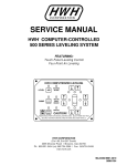
HWH COMPUTER-CONTROLLED
610 SERIES LEVELING SYSTEM
R
FEATURING:
Touch Panel Control
Single Hose
Central Grounding
Straight-Acting Jacks
Standard Two Wire Warning Switches
HWH COMPUTERIZED LEVELING
l
ON
EXCESS
SLOPE
LEVEL
STORE
NOT IN
PARK/
BRAKE
TRAVEL
OFF
CAUTION!
UNDERSTAND OPERATOR’S MANUAL BEFORE USING. BLOCK FRAME AND TIRES
SECURELY BEFORE REMOVING TIRES OR CRAWLING UNDER VEHICLE.
HWH CORPORATION
(On I-80, Exit 267 South)
2096 Moscow Road | Moscow, Iowa 52760
Ph: 800/321-3494 (or) 563/724-3396 | Fax: 563/724-3408
www.hwh.com
ML1681/MI91.0002
06MAY04
SECTION 1
N
TIO
SEC
1
E
UBL
O
R
T
TING
O
O
SH
PS
STE
SECTION
2
REPAIR STEPS
SEC
TION
3
DIAG
RAM
S
3 PART FOLDER
HOW TO USE MANUAL
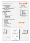
This manual is written in three sections. Section 1 is the Trouble Shooting Steps. Section 2 is the Repair Steps. Section 3 is
the Diagrams. Begin diagnosis of the system with Section 1, the Trouble Shooting Steps. This will give the correct operation
and function of the system. When a malfunction is encountered, the Trouble Shooting Steps will direct you to the proper Repair
Steps in Section 2, the Repair Steps. The Repair Steps are broken into 3 columns, Problem, Solution, and Diagram. In the
proper part under Problems, find the symptom you have encountered. The testing and repair for that problem is in the Solution (center) column. Diagrams for a particular Problem and Solution are in the Diagram (right hand) column. This column will
direct you to the proper diagram in Section 3, Diagrams, for a more detailed view.
Before beginning your repair, it is IMPORTANT to read the CAUTIONS and NOTES AND CHECKS in the first section, TROUBLE
SHOOTING STEPS. In many cases this will save time and mistakes when trouble shooting a system.
This Repair Manual is offered as a guide only. It is impossible to anticipate every problem or combination of problems. This
manual is written in sequential order of the proper operation of the system. The Trouble Shooting Steps must be followed in
order to give correct diagnosis of the problem(s). For any problems encountered that are not addressed in this manual, contact
HWH Corporation for assistance.
NOTE: Diagrams in this manual are of typical systems. There may be plumbing or harness differences. In most cases
this should not effect trouble shooting procedures.
PROCEED WITH TROUBLE SHOOTING GUIDE
MI91.1015
18JUN01
TROUBLE SHOOTING
WARNING!
BLOCK FRAME AND TIRES SECURELY BEFORE CRAWLING UNDER VEHICLE. DO NOT USE THE LEVELING
JACKS OR AIR SUSPENSION TO SUPPORT VEHICLE WHILE UNDER VEHICLE OR CHANGING TIRES. VEHICLE
MAY DROP AND OR MOVE FORWARD OR BACKWARD WITHOUT WARNING CAUSING INJURY OR DEATH.
WHEN ROUTING OR REROUTING HYDRAULIC HOSES AND WIRES, BE SURE THEY ARE NOT EXPOSED TO ENGINE
EXHAUST OR ANY HIGH TEMPERATURE COMPONENTS OF THE VEHICLE.
THE JACKS MAY ABRUPTLY SWING UP WHEN THE FOOT CLEARS THE GROUND OR WHEN THE JACK REACHES
FULL EXTENSION.
NEVER PLACE HAND OR OTHER PARTS OF THE BODY NEAR HYDRAULIC LEAKS. OIL MAY CUT AND
PENETRATE THE SKIN CAUSING INJURY OR DEATH.
SAFETY CLASSES ARE TO BE WORN TO PROTECT EYES FROM DIRT, METAL CHIPS, OIL LEAKS, ECT. FOLLOW
ALL OTHER SHOP SAFETY PRACTICES.
DO NOT OVER EXTEND THE REAR JACKS. IF THE WEIGHT OF THE VEHICLE IS REMOVED FROM ONE OR BOTH
REAR WHEELS, THE VEHICLE MAY ROLL FORWARD OR BACKWARD OFF THE JACKS.
NOTES AND CHECKS
Read and check before proceeding with Trouble Shooting Steps.
NOTE: HWH CORPORATION ASSUMES NO LIABILITY
FOR DAMAGES OR INJURIES RESULTING FROM THE
INSTALLATION OR REPAIR OF THIS PRODUCT.
7. Do not replace the control box unless the repair steps say
to replace it. Otherwise the malfunctions may damage the
new control box.
1. If the jacks cannot be retracted, see TROUBLE SHOOTING Step
10 for temporary measures. Make sure the manual retract
valves are closed before trouble shooting.
This manual is intended for use by experienced mechanics
with knowledge of hydraulic and automotive electrical
systems. People with little or no experience with HWH
leveling systems should contact HWH technical service
(800-321-3494) before beginning. Special attention should
be given to all cautions, wiring, and hydraulic diagrams.
2. The Trouble Shooting Guide must be followed in order. Problems checked for in one step are assumed correct and not
checked again in following steps.
3. Check that the oil reservoir is full with the jacks in the fully
retracted position.
4. Most coaches have more than one battery; one for the engine
and the other(s) for the coach. The engine battery supplies
power for the control box and hydraulic pump. DO NOT use
the coach batteries to supply power to the pump. Batteries
under no load should read 12.6 volts. Batteries must maintain
good voltage under load. Batteries must be in good condition
with no weak cells. An alternator, converter or battery charger
will not supply enough power for the system to operate properly.
5. The control box monitors the engine battery during the
"AUTOMATIC LEVELING and RETRACT" modes of operation.
The battery symbol on the touch panel will be lit when battery
voltage drops below 8.5 - 9.0 volts, but the system will continue to function. Have the batteries properly charged to their
full capacity.
6. Proper grounding of all components is critical. See the electrical
circuit for specific grounds required. Faulty grounds, especially
for the control box, solenoid manifold or the pump assembly,
may cause control box component damage and /or improper
or erratic operation.
Special note: When installing a new control box, make
sure the box is properly grounded before applying power
to the system.
Tightening of hose ends: If tightening a new hose end,
make the hose end snug (finger tight) on the fitting, then
tighten the hose end 1/3 turn (2 FLATS). If tightening an
existing hose end, tighten the hose end to snug plus 1/4
turn (1 FLAT).
Suggested tools for trouble shooting the HWH leveling systems:
JUMPER WIRES(UP TO 10 GAUGE)
PRESSURE GAGE(3500 PSI MIN.)
MULTI-METER
12 VOLT TEST LIGHT
PROCEED WITH THE TROUBLE
SHOOTING STEPS ON THE
FOLLOWING PAGE
MI91.1020
21APR11
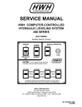
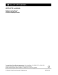
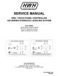
TROUBLE SHOOTING STEPS
"NOT IN PARK"
Indicator light
HWH COMPUTERIZED LEVELING
HYD LEVEL
JACK STORAGE
Indicator light
"STORE"
Button
EXCESS
SLOPE
LOWER RIGHT SIDE
Manual button
STORE DUMP
TRAVEL
CAUTION!
UNDERSTAND OPERATOR’S MANUAL BEFORE USING. BLOCK FRAME AND TIRES
SECURELY BEFORE REMOVING TIRES OR CRAWLING UNDER VEHICLE.
"OFF"
Button
"TRAVEL"
Indicator light
JACK DOWN
Indicator light
(4) red
RAISE RIGHT SIDE
Manual button
NOT IN
PARK/
BRAKE
OFF
"DUMP"
Button
LOWER FRONT
Manual button
RAISE FRONT
Manual button
HYDRAULIC OPERATION
Indicator light
"HYDRAULIC"
Button
LOW BATTERY
Indicator light
"EXCESS SLOPE"
Indicator light
LEVEL SENSING
Indicator light
(4) yellow
RAISE REAR
Manual button
RAISE LEFT SIDE
Manual button
1. Make sure the transmission is in the recommended position
for parking and the park brake is set. With the ignition switch
off, there should be no power to the leveling system. If any
touch panel lights are on, see Part 1 of the Repair Steps.
2. Turn the ignition switch to "ACC". Only the green travel
lights should be lit at this time. If this is not so, see Part 2 of
the Repair Steps.
3. Push the "I" (HYD) button one time. The red indicator light
above the "I" (HYD) button should glow steady. One or two yellow level indicator lights may be on. The green travel light will
still be on. The "NOT IN PARK/BRAKE" light should NOT be
lit. The pump should not run. If this is not so, see Part 3 of
the Repair Steps.
4. After pushing the "I" (HYD) button one time, the operator
can manually operate the jacks with the eight buttons (arrows)
on the right half of the touch panel. The up arrow will lift the
vehicle by extending the jacks; whereas, the down arrows
will lower the vehicle by retracting the jacks. The jacks operate
in pairs; left side, right side, front or rear. Press the up arrow
button for each jack pair, checking the proper pair of jacks
operate. Press the down arrows to make sure the jacks will
retract properly. If any of these functions do not work properly, see Part 4 of the Repair Steps.
NOTE: If the LOW BATTERY light comes on it will not
interfere with the operation of the system, but battery
voltage and connections should be checked.
5. Air dump test for vehicles with air dump option. The air
dump button will work either with the leveling system off and
the ignition on, or with the leveling system on. There should
be one air dump valve for each height control valve. The
air dump valves may be equipped with emergency shutoff
valves make sure they are open. With the system off and the
LOWER LEFT SIDE
Manual button
LOWER REAR
Manual button
ignition on and the engine running, push the dump button.
The air should dump from the suspension while the dump
button is being pushed. When the dump button is released,
the air should stop dumping and the vehicle should return to
proper ride height. Again with the engine running, push the
"I" (HYD) button. The air dump button should work at this time.
Air will dump from the system when the button is depressed
and stop dumping when released. The vehicle should return
to the proper ride height. If this does not function properly,
see Part 5 of the Repair Steps section.
6. Sensing unit check. If the vehicle is equipped with air dump,
dump the air at this time. Using a bubble level the inside of
the vehicle, level the vehicle using the button on the right side
of the panel as described in Part 4 above. All yellow lights
should be off at this time. If not, the sensing unit may need to
be adjusted.
When a yellow light is on it indicates that side or end of the
vehicle is low according to the sensing unit. Check also that
all lights can be made to come on (at different times) by extending or retracting jacks. If the ground is sloping or uneven,
the vehicle may need to be moved to complete the test. For
sensor adjustment procedures or diagnostic procedures, see
Part 6 of the Repair Steps.
At this time, manually retract all jacks to their fully stored
position. From this point on, it is assumed the system is
fully functional in the manual mode. Whenever a malfunction occurs, revert to the manual operation and check for
correct functioning. If a problem is found in the manual
operation, trouble shoot the problem using the preceding
steps. Remember, low volts can cause erratic operation
and damage components.
MI91.1025
08MAY00
TROUBLE SHOOTING STEPS
CONTINUED
AUTOMATIC LEVELING
7. Turn the ignition switch to the "ACC" position. For vehicles
with automatic air dump, the engine must be off during leveling.
Press the "I" (HYD) button. The red indicator light above the
"I" (HYD) button will be lit. Set the park brake if the "NOT
IN PARK/BRAKE" light is on. Press the "I" (HYD) button a
second time. This will start the automatic leveling process.
The following should occur:
a. The red indicator light above the "I" (HYD) button will start
to flash.
b. Vehicles equipped with automatic air dump will dump the air
at this time. The system will dump air for approximately 45
seconds before continuing. The dump valves will remain open
until the leveling system has automatically shut itself off.
c. Two jacks at a time will extend corresponding to any yellow
light(s) which is/are lit. This will continue until all yellow level
light(s) are out or until one or two jacks have reached their full
extension. If the excess slope light comes on, the system will
not stabilize. The panel will stay on for 2 minutes, then shut
off. (Older systems will shut off after 10 seconds.)
d. The red light "JACKS DOWN" indicator lights will come on
for each jack when the jack is extended 2 or more inches.
e. After a pause, the pump will come on and run until all remaining jacks not touching the ground, extend to the ground
to stabilize the vehicle. Through a pressure switch on each
jack, the control box automatically senses when each jack is
firmly on the ground. The computer constantly rechecks all
the jack pressure switches and will return to any jack that has
lost its pressure switch signal until all four jacks have reached
the minimum stabilize pressure. If either front jack pressure switch
is off, both front jacks will stabilize. Jacks used to stabilize the
the vehicle should lift the coach a minimum of 1/2 inch.
f. The red indicator light above the "I" (HYD) button will stop
flashing, the red indicator light will go out as the system shuts
off. If any of the above does not function properly, see Part 7
of the REPAIR STEPS.
"EXCESS SLOPE": The "EXCESS SLOPE" light will only
come on in the automatic leveling mode. If there is a problem
with the "EXCESS SLOPE" light, refer to Part 7C of the
REPAIR STEPS. The "EXCESS SLOPE" light will come on
during stabilize if the pump does not shut off and the manifold
pressure switch is tripped.
RETRACT PROCEDURE
8. For systems with automatic air dump, start the vehicle engine
to build up the air pressure and leave it running. If the dump
valves are not closed, see Part 6 of this section.
9. Push the "I" (HYD) button one time. The red indicator light
above the "I" (HYD) button will glow steady. The pump should
NOT be running. Push "STORE" button. The following should
occur:
a. The red indicator light above the "STORE" button should
start to flash.
b. The jacks should retract to the store position. The front
jacks will retract for 5 seconds before the rear jacks start to
retract.
c . The red warning lights on the touch panel should go out
when the jacks are extended less than 2 inches.
d. The master warning light should go out.
e. The green "TRAVEL" light should come on.
f. The red indicator light above the "STORE" button will stop
flashing and the computer will automatically shut off. The only
light that should be lit on the touch panel will be the "TRAVEL"
light. If any of the above does not occur, see Part 8 of the
Repair Steps.
NOTE: The system will automatically retract for 6 minutes after all
red warning lights are out, unless 1 or more red warning lights
stay lit. If a warning light stays lit, the system will continue to retract for 30 minutes and then shut down regardless of any lit warning lights.
CAUTION:
UNLESS TROUBLE SHOOTING, THE
LEVELING SYSTEM MUST BE ALLOWED TO RETRACT
THE FULL 6 MINUTES BEFORE INTERRUPTING POWER
TO THE COMPUTER.
10. EMERGENCY JACK RETRACTION: Each solenoid valve
is equipped with a "T" handle release valve. Turn the handle
counter clockwise approximately 3 turns or until the jacks start
to retract. The oil will return to the reservoir and the jack
should retract. After all the jacks are fully retracted, turn the
"T" handles clockwise until snug. If no jacks retract, close
all "T" handles and make sure the Touch Panel is OFF.
Remove then reassemble any one check valve cap. (SEE
MP65.0) The system should then store. If not, contact HWH
Customer Service for assistance. See Part 9 of the REPAIR
STEPS.
MI91.1030
25JUN01
SECTION 2
REPAIR MANUAL
HWH COMPUTER-CONTROLED LEVELING SYSTEM
610 SERIES
FEATURING:
TOUCH PANEL CONTROL
SINGLE HOSE
CENTRAL GROUNDING
STRAIGHT-ACTING JACKS
BEGIN WITH SECTION 1
ML1681/MI91.2025
07MAR01
REPAIR STEPS
PROBLEM
SOLUTION
Part 1
Touch panel has
indicator lights
on with the ignition switch off.
There should be no +12 power to the 8" control box. Trace the (BROWN)
6120 wire in the 3 pin UML connector to its source. The wire should be
connected to accessory power.
FIGURES
ACCESSORY
REFER TO MP85.5005
Part 2
With the ignition
switch on:
a. The green
"TRAVEL" light
nor the master
"JACKS DOWN"
warning light is
lit.
With the ignition switch on, the (BROWN) 6120 wire in the 3 pin UML
connector should have +12 power. If not, trace the wire to its source.
Check any inline fuses. If +12 power is present, check the 5 amp"ACC"
fuse on the 8" control box. Check that the 10 guage (WHITE) 6230
wire is properly grounded to the frame. If it is okay, the problem is
most likely in the 8" control box. but it could be in the touch panel, or
the moduler cable.
#10 GROUND WIRE (WHITE) 6230
ACC.
ACC. FUSE
REFER TO MP85.5005
CONTROL HARNESS
6.00"
FROM
END
OF LOOM
REFER TO MP85.5045
b. The master
"JACKS DOWN"
warning light is
on. (Jacks are all
in the stored position)
Push the "I" (HYD) button one time. A red jacks down warning light
on the touch panel should come on, indicating a jack is down. If a
light comes on, unplug the jack warning switch for that light. If the
light goes out, replace the warning switch. If replacing the warning
switch does not fix the problem, the magnet in the jack may be bad.
Contact HWH technical service. If not, unplug the 9 wire MTA
connector for warning switches at the 8" control box. If the red
warning light goes out, the wire to the jack warning switch is
shorted to ground. If the red warning light stays on, replace the 8"
control box.
NOTE: Make sure the white wires of the harness and warning
switch are in the "A" pins of the Packard connectors. The black
wires must be in the "B" pins of the connectors.
If no red warning light on the touch panel comes on, check the wires
to the master warning light. If the wires are okay, replace the 8" control
box.
REFER TO MP85.5010
LR - (GREEN) 4000
RR - (BLACK) 3000
RF - (RED) 2000
LF - (YELLOW) 1000
GRD - (WHITE) 6235
POSITIVE
VOLTAGE (PURPLE) 6121
CONTROL (BROWN) 7699
MASTER
WARNING
LIGHT
REFER TO MP85.5001
MI91.2030
15MAY08
PROBLEM
SOLUTION
FIGURES
Part 2
Continued
c. The touch panel
has indicator lights
on other than the
green "TRAVEL"
indicator.
Turn the ignition switch off then back on. If the lights do not go out,
the problem is most likely the 8" control box, but it could be the touch
panel or the modular cable.
Part 3
After pushing
the "I" (HYD)
button one time:
a. The red indicator light above the
"I" (HYD) button
does not come
on.
#10 GROUND WIRE (WHITE) 6230
Check the voltage on the (BROWN) 6120 wire in the 3 pin UML connector. It should be 12.5 volts or more. Check that the 10 gauge (WHITE)
6230 wire is grounded correctly to the central ground stud. If good voltage is present, replace the control box, touch panel, or cable assembly.
If voltage is not present, check the power source for the (BROWN) 6120
wire. Check that the cable between the touch panel and the control box
is properly connected.
ACC.
ACC. FUSE
REFER TO MP85.5005
CONTROL HARNESS
REFER TO MP85.5045
REAR
RED
R SIDE
b. More than two
yellow lights are
lit or opposite
yellow lights are
lit.
c. The "NOT IN
PARK / BRAKE"
light is lit.
Unplug the sensing unit MTA connector from the 8" control box. If
the lights do not go out, replace the control box. If the lights go out,
connect a 12 volt test light to ground. There are five pins for the
sensing unit. One pin for ground and one pin for each yellow level
indicator light. Touch each of the four pins for the level indicator lights.
Only one light per pin should come on. If this is so, replace the
sensing unit. If not, replace the control box.
GREEN
FRONT
BLACK
L SIDE
YELLOW
WHITE
GND
SENSING
UNIT
INPUT
REFER TO MP85.5005
Check that the transmission is in the proper park position and that the
park brake is set. Some park brakes automatically set when the transmission is placed in park. Trace the (BLUE) 9000 wire in the 6 pin UML
connector to its source. Check for the proper position of the diode arrangement. Check the brake switch for proper function.
NOTE: Most coaches complete a ground signal through the brake switch
but some do have a +12 signal. Make sure the proper box is being used.
Use a jumper wire to apply the proper signal to the (BLUE) 9000 wire.
If the "NOT IN PARK/BRAKE" light does not go out, replace the control
box.
PARK - (BLUE) 9000
REFER TO MP85.5005
TO PARK
BRAKE
SWITCH
(LABELED) 9000
TO BRAKE
LIGHT ON
DASH
(LABELED) 9001
SEE CONTROL BOX
CONNECTION
INFORMATION
(BLUE)
9000
REFER TO MP85.5035
MI91.2035
04MAR99
PROBLEM
SOLUTION
Part 3
Continued
FIGURES
RELAY B CONN. DIAGRAM
GRAY
FROM
HYD.
HARN.
d. The pump
comes on at this
time.
If possible, release the park brake. If the pump continues to run replace relay B. Otherwise, check Terminal 5 with a 12 volt test light
connected to ground. If +12 volts is present, the problem is with the
control box. If +12 is NOT present replace relay B.
REFER TO MP85.5030
e. All the indicator
lights on the touch
panel come on
and stay on.
If all the indicator lights come on and stay on, replace the control box.
NOTE: All indicator lights will flash momentarily when turning the
system on.
Part 4
Manual
Operation
a. The proper
jacks do not extend when an up
arrow is pushed.
The problem is probably the hose routing or wire connections at the
manifold. Check the wiring and hydraulic diagrams for proper routings.
b. The pump
does not come
on.
If the LOW BATTERY light comes on, check the 40 amp fuse in the
(BLACK) 6800 wire.
REFER TO MP85.5040
BLACK
MANIFOLD/PUMP
HARNESS.
40 AMP
FUSE
WHITE
RED
#1
Push the "OFF" button then the "I" (HYD) button one time. Check
Terminals 1,2 and 3 of relay A. They should have +12 volts. If
Terminal 1 does not have +12 volts, the control box or the (RED)
8500 wire is bad. If Terminal 2 has no voltage, check the cable,
cable ends and battery. If Terminal 3 has no voltage, connect a test
light to Terminal 2 and check Terminal 8. Terminal 8 supplies ground
for relay A. If the test light comes on, replace relay A. If the test light
does not come on, check that all wires are properly hooked up to the
grounding stud and that the grounding stud is tight and properly
attached to the vehicles frame. The (WHITE) 6231 wire on Terminal
8 could be bad. Check the 40 amp in-line fuse holder on the #10
wire connected to Terminal 3. If Terminals 1,2 and 3 are OK proceed.
#3
RELAY A
(MASTER RELAY)
FROM
BATTERY
REFER TO MP85.5030
CONTROL HARNESS
The following test must be performed while an up arrow is being
pushed. With a test light hooked to ground , check Terminals 5 and
6 while the up arrow is being pushed. If Terminal 5 has no voltage,
check the pump fuse at the control box. If the fuse is good replace
the control box. If the fuse is blown the gray wire may be shorted or
relay B may be bad.
REFER TO MP85.5045
If Terminal 5 has voltage but not Terminal 6, check Terminal 7 with a
test light hooked to Terminal 2 of relay A. Terminal 7 supplies the
ground for relay B. If the test light comes on, replace relay B. If the
test light does not come on check the connections at the grounding
stud. Make sure the grounding stud is properly attached to the frame.
The (WHITE) 6231 wire could be bad.
REFER TO MP85.5030
If Terminal 5 and 6 have voltage, check the connection at Terminal 9.
Check that the connection at Terminal 10 is tight. Check that the pump
ground cable is properly attached to the grounding stud.
NOTE: Some pumps will not have Terminal 10 or a ground strap.
Check that the pump has a good solid frame mount. If all connections
and mountings are okay, replace the pump.
MI91.2040
08MAY00
PROBLEM
Part 4
Continued
SOLUTION
If the vehicle is equipped with a HWH room extension, check that
that the room retract solenoid valve is not open.
FIGURES
PUMP/MANIFOLD
ASSEMBLY
c. The pump runs
under no load and
nothing happens,
or jacks extend
but will not lift the
vehicle.
Disconnect the pressure tube between the manifold and shuttle valve.
Connect the pressure gauge to the fitting in the manifold. (Not the
shuttle valve.) Turn the pump on for 5 to 10 seconds. The pressure
should be approximately 3500 PSI. If there is low pressure, (less
than 3100P.S.I.) change the power unit. If the pressure is okay
change the shuttle valve.
d. A jack will not
extend when the
up arrow is
pushed. (or
extends slowly)
Check the fuse at the control box for the jack that is not working. A
shorted solenoid valve or harness wire can blow the fuse. If the fuse
is not blown, continue.
REFER TO MP65.0
RIGHT
RIGHT
LEFT
LEFT
REAR
FRONT
FRONT
REAR
(Rear
Make sure the solenoid valve T-Handles are closed. Push the OFF
button on the Touch Panel as soon as the EXTEND (up arrow)
button is released. If the jack stays down replace the control box.
If the jack does not stay down replace the solenoid valve.
f. A red warning
light will not come
on when its jack
is extended 2
inches.
When operating the jacks using the manual buttons, make sure the
proper warning light comes on as a jack extends. Return the jacks
to the store position. Unplug the jack warning switch for the light not
working. The warning switch has a 2-pin connector. Put a jumper
wire between the 2 pins of the harness connector. If the light comes
on, replace the warning switch. If the light does NOT come on, unplug the orange MTA connector for the warning switches at the control
box. Use a 12 volt test light connected to the ground pin for warning
switch inputs. Touch each pin in the control box. If the red warning
lights work properly, the wire from the jack is bad. If the red lights
DO NOT come on, replace the control box.
Refer to Part 10 of Section 1. If the T-Handle release does not work,
loosen the hydraulic line for that jack at the manifold. If the jack
retracts properly the problem is the solenoid valve or velocity valve.
Remove the fitting from the velocity valve. Remove the poppet and
2 springs. Replace the fitting and retry. If the jack retracts properly,
replace the velocity valve. If not replace the solenoid valve. If the
jack does not retract after the valve has been replaced, the problem
may be the outer check valve. Contact HWH Customer Service if a
check valve problem is present. If the jack does not retract, loosen
the hydraulic line at the jack. If the jack retracts, the line is bad. If the
jack does not retract, replace the cylinder.
YELLOW
BROWN
WHITE
BLUE
YELLOW
GREEN
WHITE
ORANGE
view)
If the problem is a front jack, interchange wires for the front solenoids.
If the problem is a rear jack, interchange the wire for the rear solenoids.
Retry using the correct up arrow . If the problem stays with the same
jack, the problem is the jack, hydraulic line to the jack, the inner check
valve or the solenoid valve. Open the T-Handle for the valve and
retry. If the jack extends replace the solenoid valve. If the jack does
not extend, reconnect the wires properly and swap the hoses. If the
jack will not extend, the problem is the hose or the jack. If there is no
fluid flow to the jack, replace the hose. If there is fluid flow, replace
the jack. If the jack extends with the hoses swapped, the problem
may be the inner check valve. Contact HWH Customer Service if a
check valve problem is present.
e. A jack will not
stay extended
when the up arrow is released.
g. One or more
jacks will not
retract or
retracts very
slowly.
SHUTTLE VALVE
REFER TO MP85.5040
REFER TO MP85.5010
GREEN LR
BLACK RR
RED
RF
YELLOW LF
WHITE GROUND
POSITIVE VOLTAGE
CONTROL
MASTER WARNING
LIGHT
REFER TO MP85.5005
EMERGENCY
VALVE
RELEASE
REFER TO MP65.0
MI91.2045
25JUN01
PROBLEM
SOLUTION
FIGURES
Part 4
Continued
g. One or more
jacks will not
retract or
retracts very
slowly.
If the jack retracts with the T-Handle, check for voltage in the plug
for that valve while the retract button is being pushed. If voltage is
present the solenoid valve is bad. If voltage is not present, the
problem is the harness or the control box. Check for voltage for that
valve at the control box.
If no jacks can be retracted with the T-Handles, replace the shuttle
valve.
Part 5
IF AIR DUMP SOLENOID IS EQUIPPED
WITH MANUAL SHUT OFF, KEEP SHUT
OFF IN THE OPEN POSITION.
a. Air will not dump
from the suspension.
b. Air dump valves
will not close.
With the leveling system off and the ignition on, check between the
wires going to the air dump valves for +12 volts while the dump button
is being pushed. If +12 volts is present replace the valve. If +12 volts
is not present, check the 5 amp air dump fuse. Check for +12 volts
on the (GRAY) 9300 wire in the 9 pin UML connector at the control box.
If +12 is not present replace the control box. Check that the white wire
has a ground. NOTE: Some air dump valves are equiped with an emergency shut off valve. Make sure this valve is open.
{PARALLEL WITH MANUAL
VALVE BODY AS SHOWN.}
REFER TO MP75.2
With the ignition on, Check the (GRAY) 9300 wire in the 9 pin UML
connector at the box. If +12 volts is present, replace the control box.
If +12 volts is not present, replace the air dump valve. If the valve is
closed but the vehicle will not return to proper ride height, the problem
is probably in the height control valve or the air supply from the suspension system.
GRAY
DUMP
DUMP
FUSE
REFER TO MP85.5005
Part 6
Yellow level indicator does not
work properly.
The sensing unit is a 4 inch diameter disk that is usually mounted on the under side of the vehicle towards the middle of the vehicle. Occasionally it will be found inside the coach or in a storage compartment. Check that the unit is not mounted, nor the wires routed
near a heat source. Check that the sensing unit is mounted correctly according to the sticker on the sensing unit. The sensing unit is adjusted
by drawing up the corresponding screws (if the sensing unit is mounted under the vehicle) to put out the yellow lights. If the yellow lights
are not working properly, unplug the sensing unit at the control box.
Using 12 volt test light connected to ground, touch each pin in the
control box for the sensing unit. Check that the proper yellow light
on the touch panel comes on when its pin is touched. Only one light
should be lit when a pin is touched. If there is a malfunction here,
replace the control box. If the control box is okay, replace the sensing
unit. Remember to keep the sensing unit away from any heat source.
REFER TO MP85.9505
REAR
RED
R SIDE
GREEN
FRONT
BLACK
L SIDE
YELLOW
WHITE
GND
SENSING
UNIT
INPUT
REFER TO MP85.5005
Part 7
After pushing the
"I" (HYD) button
a second time :
a. The red indicator light does not
flash.
AUTOMATIC LEVELING
The problem is in the touch panel or control box. Make sure all
Touch Panel and Control Box connections are OK.
MI91.2050
25JUN01
PROBLEM
SOLUTION
IF AIR DUMP SOLENOID IS EQUIPPED WITH
MANUAL SHUT OFF, KEEP SHUT OFF IN THE
OPEN POSITION. (PARALLEL WITH MANUAL
VALVE BODY AS SHOWN.)
Part 7
Continued
b. The air does not
dump at this time.
(If applicable)
FIGURES
Recheck Part 6a of this section. If the air will dump manually but not
automatically, replace the control box. If the air will not dump at all,
check that the correct control box was used.
REFER TO MP75.2
RIGHT
REAR
RIGHT
FRONT
LEFT
FRONT
LEFT
REAR
YELLOW
BLACK
BROWN
WHITE
BLUE
YELLOW
GREEN
(REAR
VIEW)
WHITE
The "EXCESS
SLOPE" light
comes on when
it shouldn’t or
won’t come on
when it should.
It is assumed at this point wiring and hose routings have been
checked and are okay. It is also assumed that the sensing unit is
functioning properly. Recheck the manual operation of the system. If
the excess slope light is coming on and a jack has not reached full
extension, unplug the wire to the pressure switch on the manifold
and retry. If it now works replace the pressure switch. If not the jack
may be too small. Check with HWH. If the excess slope light will
not come on when two jacks reach full extension, disconnect the
tube between the shuttle valve and the manifold. Check the pump
pressure. If the pump pressure is okay, retry in automatic leveling
and short the wires to the pressure switch together while the pump is
running with a yellow leveling light on. If the excess slope light does
not come on, replace the control box. If the light comes on replace
the pressure switch. During the leveling process, at no time should
any jacks retract. If the vehicle or a corner of the vehicle seems to
drop or a jack is retracting while the pump is running, the problem is
an internal check valve. Contact HWH Corporation, 1-800-321-3494,
for proper repair procedure.
ORANGE
c. The vehicle will
not level correctly
according to the
yellow level indicator lights.
REFER TO MP85.5040
PUMP/MANIFOLD
ASSEMBLY
SHUTTLE VALVE
REFER TO MP65.0
d. One or more
jacks are not stabbilizing the vehicle
properly.
One or more jacks do not reach the ground.
At this point it is assumed that all jacks will extend and lift the vehicle.
If the jack does not attempt to move to stabilize the vehicle, unplug
the jacks pressure switch for that jack and retry. If the jack now extends and lifts the vehicle during stabilize, replace the pressure switch.
If it still does not move review Part 5 of Section 1.
NOTE: With a jack pressure switch unplugged, that jack will lift the
vehicle out of level. Do not allow the jacks to over extend when
performing this test.
If a jack extends but does not reach the ground or lift the vehicle
enough, first adjust the pressure switch. Remove the rubber boot
from the body of the switch. Unplug the wire so it can rotate freely.
Loosen the locking nut and turn the pressure adjust body 1/2 turn
clockwise. Retry and repeat the procedure if still not stabilizing. If
adjusting the pressure switch does not help, replace the switch. A
jack should lift the vehicle at least 1/2" during stabilize. (7d continued
on the next page)
RUBBER BOOT
PRESSURE ADJUST
BODY
LOCKING
NUT
REFER TO MP85.5010
MI91.2055
19JUN01
PROBLEM
Part 7d
Continued
SOLUTION
One or more jacks lift the vehicle too much during stabilize.
The computer must see both front jack pressures before stopping the
front jacks. If one front jack pressure switch needs adjustment or is
bad, both jacks will lift too much. To adjust the pressure switch to
decrease the amount of lift during stabilize, remove the rubber boot
from the switch body. Unplug the wire so it can rotate freely. Loosen
the locking nut. Turn the pressure adjust body counter clockwise 1/2
turn.
Retry and repeat the procedure until the system properly stabilizes
the vehicle. A jack should lift the vehicle at least 1/2" during stabilize.
If adjusting one front switch does not help, try adjusting the other
front switch. The rear jack pressure switches work individually. If
adjusting the switches does not help, replace the pressure switch.
To determine which front switch is bad, unplug either switch. Use a
jumper wire to ground the harness pin for that switch. If the jacks continue to lift too much the switch that remains plugged in is bad and
should be changed. If the front jacks now stabilize properly, replace
the switch that is unplugged.
FIGURES
REFER TO MP85.5010
AUTOMATIC RETRACT
The vehicle will
not return to ride
height.
The air dump solenoids are not closing. Recheck Part 6b of this
section. Some air solenoids are equipped with emergency shutoff
valves. If the dump valves are closed, the height control valve or air
supply for the suspension may be the problem.
Part 8
After pushing
the "I" (HYD)
button one time
and pushing the
"STORE" button:
a. The pump
comes on after
pushing the "I"
(HYD) button one
time.
Solenoid B, the pump solenoid, is probably stuck. The system cannot
retract if the pump is running. Recheck Part 3d of this section.
b. A jack will not
retract.
Unplug the left front and the left rear solenoid valves. Put the system
in the "STORE" mode. If the right side jacks retract, replace the left
rear solenoid valve.
Unplug the right front and the right rear solenoid valves. Put the
system in the "STORE" mode. If the left side jacks retract, replace
the right front solenoid valve.
REFER TO MP85.5040
c. Red warning
lights on the touch
panel do not go
out, but the jacks
have retracted.
Unplug the warning switch wire. If the light goes out, replace the
warning switch. If replacing the warning switch does not fix the
problem, the magnet in the jack may be bad. Contact HWH
technical service. If the light does not go out, check the wire for a
short to ground. If the wire is okay replace the control box.
NOTE: Make sure the white wires of the harness and warning
switch are in the "A" pins of the Packard connectors. The black
wires must be in the "B" pins of the connectors.
REFER TO MP85.5010
MI91.2060
15MAY08
PROBLEM
SOLUTION
FIGURES
Part 8
Continued
d. The master
"JACKS DOWN"
warning light on
the dash will not
go out.
Unplug the 6 pin MTA connector and check the ground wire going to
the master warning light. If it is not shorted to ground, replace the
control box. This light should be on whenever a warning light on the
touch panel is on.
MASTER
WARNING
LIGHT/
BUZZER
OUTPUTS
CONTROL
POSITIVE
VOLTAGE
REFER TO MP85.5005
e. The green travel
light will not come
on.
Part 9
Jacks will NOT
retract using the
T-handle release
on the solenoid
valves.
The green travel light will not come on if any red warning lights are
on. If no red warning lights are lit, replace the control box.
If none of the jacks will retract using the T-handles, the shuttle valve
is bad.
If only one jack will not retract using the T-handles, loosen the hydraulic line for that jack. If the jack retracts, replace the solenoid
valve. If the jack does not retract, the hose could be kinked or the
actuator or jack is bad.
EMERGENCY
VALVE
RELEASE
REFER TO MP65.0
MI91.2065
10JAN96
HYDRAULIC LINE CONNECTION DIAGRAM
LEVELING SYSTEM
FRONT
NOTE: BEFORE OPERATING VALVE RELEASE
"T" HANDLES, READ AND UNDERSTAND
PROCEDURE FOR MANUAL JACK RETRACTION
IN OPERATOR’S INSTRUCTIONS.
PUMP/MANIFOLD
ASSEMBLY
VALVE RELEASE
"T" HANDLES
SHUTTLE
VALVE
CHECK VALVE CAPS (4)
MANIFOLD FITTING
NOTE: SOME MANIFOLDS ARE
EQUIPPED WITH VELOCITY VALVES
LF
RF
VELOCITY VALVE
LR
RR
MP65.0
18JUN01
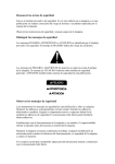
HYDRAULIC SCHEMATIC
BI-AXIS LEVELING WITH STRAIGHT-ACTING JACKS
RELIEF VALVE
M
12 VOLT D.C.
HYDRAULIC
POWER UNIT
RETURN
SOLENOID MANIFOLD
ASSEMBLY
PRESSURE
PRESSURE/RETURN
SHUTTLE VALVE
CHECK
VALVE
INNER
SOL.VALVE
LR
SOL.VALVE
LF
3000 PSI
SWITCH
SOL.VALVE
RF
SOL.VALVE
RR
CHECK
VALVE
OUTER
LEFT
FRONT
RIGHT
FRONT
JACK
PRESSURE
SWITCH
JACK
CYLINDER
LEFT REAR
RIGHT REAR
MP65.4525
15MAY97
AIR LINE CONNECTION DIAGRAM
SUSPENSION
AIR BAGS
FROM WIRE HARNESS
SEE ELECTRICAL
DIAGRAM FOR
CONNECTION
AIR DUMP SOLENOID VALVES
ARE ACTIVATED (OPENED) BY
A +12 SIGNAL.
BA
BA
4 AIR DUMP SOLENOID VALVES
AND 4 HEIGHT CONTROL VALVES
ARE SHOWN.
BA
BA
HEIGHT
CONTROL
VALVE
THE AIR DUMP VALVE IS TO TEE
INTO THE LINE BETWEEN THE
AIR BAG AND THE HEIGHT CONTROL
VALVE. THREE HEIGHT CONTROL
VALVES ARE THE MOST COMMON
ON AIR SUSPENSION SYSTEMS.
2, 3 OR 4 CONTROL VALVES MAY
BE USED.
USE ONLY DOT
APPROVED
FITTINGS AND
TUBING.
NEW LINE
3/8" O.D. TUBE
EXISTING
LINE
SUSPENSION
AIR BAGS
MP75.2
15MAY97
CONNECTION INFORMATION
610 SERIES LEVELING SYSTEM
LR - (BROWN) 4400
RR - (ORANGE) 3400
LR GROUND (YELLOW/BLACK) 7601
LF - (BLUE) 1400
RF - (GREEN) 2400
RF GROUND (YELLOW) 7600
S10 PRESSURE SWITCH (BLACK) 8100
PUMP - (GRAY) 8600
5 AMP
10 AMP
10 AMP
10 AMP
#10 GROUND WIRE (WHITE) 6230
10 AMP
LR FUSE
#10 POWER WIRE (BLACK) 6800
5 AMP
LF FUSE
RF FUSE
RR FUSE
MASTER RELAY - (RED) 8500
PARK - (BLUE) 9000
ACC.
FUSE
+12 FROM ACC. (BROWN) 6120
PUMP FUSE
PART & SERIAL NUMBER
RED
GREEN
SENSING
UNIT INPUT
LR - (PURPLE) 4200
RR - (BROWN) 3200
RF - (ORANGE) 2200
LF - (BLUE) 1200
PRESSURE
SWITCH
INPUTS
LR - (GREEN) 4000
RR - (BLACK) 3000
RF - (RED) 2000
LF - (YELLOW) 1000
GRD - (WHITE) 6235
WHITE
YELLOW
BLACK
TOUCH PANEL
CABLE INPUT
POSITIVE
VOLTAGE (PURPLE) 6121
WARNING
SWITCH
INPUTS
MASTER
WARNING
LIGHT/
BUZZER
OUTPUTS
CONTROL (BROWN) 7699
NOTE: THE (4) DIGIT WIRE NUMBER
SUPERSEDES ANY AND ALL
WIRE COLORS
TOUCH PANEL CABLE
TOUCH PANEL
MP85.5001
11FEB99
ELECTRICAL CONNECTION DIAGRAM
610 SERIES LEVELING SYSTEMS
TO PARK
BRAKE
SWITCH
(LABELED) 9000
TO BRAKE
LIGHT ON
DASH
(LABELED) 9001
#10 WIRE TO GROUND STUD - (WHITE) 6230
TOUCH
PANEL
SEE CONTROL BOX
CONNECTION
INFORMATION
+12 (PURPLE) 6121
MASTER WARNING
LIGHT/BUZZER
CONNECTION DIAGRAM
FROM +12 ACC.
FUSED 15AMP MAX (BROWN) 6120
CONTROL - (BROWN) 7699
(BLUE)
9000
+12 POWER FOR
ELECTRONIC
SENSING UNIT ONLY
PRESS. SW. (BLUE) 1200
PRESSURE
SWITCH (ORANGE) 2200
RF
LF
BA
BA
(YELLOW) 1000
(WHITE) 6235
(WHITE)
6235
WARNING SWITCH
(RED)
2000
PUMP/MANIFOLD
HARNESS
WARNING SWITCH
MAKE ALL GROUNDING
CONNECTIONS BEFORE
APPLYING POWER
TO BOX.
MANIFOLD
WIRING DIAGRAM
FRONT
THIS
SIDE
UP
PUMP RELAY
WIRING DIAGRAM
DO NOT REVERSE WIRE
COLORS TO A & B ON
PACKARD CONNECTORS
ELECTRONIC
SENSING UNIT
POWER UNIT
GROUNDING
INSTRUCTIONS
WARNING/PRESSURE
SWITCH HARNESS
NOTE: THE (4) DIGIT WIRE NUMBER
SUPERSEDES ANY AND ALL
WIRE COLORS
(GREEN)
4000
A
B
LR
(WHITE)
6235
PRESS.
SWITCH
(PURPLE)
4200
PRESS.
SWITCH
(BROWN)
3200
(BLACK)
3000
BA
(WHITE)
6235
RR
WARNING SWITCH
MP85.5003
10JUL03
CONNECTION INFORMATION
610 SERIES LEVELING SYSTEMS
WITH AIR DUMP
LR - (BROWN) 4400
RR - (ORANGE) 3400
LR GROUND (YELLOW/BLACK) 7601
LF - (BLUE) 1400
RF - (GREEN) 2400
RF GROUND (YELLOW) 7600
S10 PRESSURE SWITCH (BLACK) 8100
LR FUSE
LF FUSE
RF FUSE
RR FUSE
DUMP FUSE
SENSING
UNIT INPUT
WHITE
YELLOW
BLACK
TOUCH PANEL
CABLE INPUT
5 AMP
PARK - (BLUE) 9000
ACC.
FUSE
+12 FROM ACC. (BROWN) 6120
PART & SERIAL NUMBER
GREEN
#10 POWER WIRE (BLACK) 6800
MASTER RELAY - (RED) 8500
7.5 AMP
PUMP FUSE
RED
5 AMP
10 AMP
10 AMP
10 AMP
#10 GROUND WIRE (WHITE) 6230
(TWO WHITE WIRES
IN THIS RING TERMINAL. ONE FOR
THE AIR DUMP.)
10 AMP
PUMP - (GRAY) 8600
DUMP (GRAY) 9300
LR - (PURPLE) 4200
RR - (BROWN) 3200
RF - (ORANGE) 2200
LF - (BLUE) 1200
PRESSURE
SWITCH
INPUTS
LR - (GREEN) 4000
RR - (BLACK) 3000
RF - (RED) 2000
LF - (YELLOW) 1000
GRD - (WHITE) 6235
POSITIVE
VOLTAGE (PURPLE) 6121
WARNING
SWITCH
INPUTS
MASTER
WARNING
LIGHT/
BUZZER
OUTPUTS
CONTROL (BROWN) 7699
NOTE: THE (4) DIGIT WIRE NUMBER
SUPERSEDES ANY AND ALL
WIRE COLORS
TOUCH PANEL CABLE
TOUCH PANEL
MP85.5005
04MAR99
STRAIGHT ACTING JACK WITH PRESSURE SWITCH
FOR 610 SYSTEMS 2-WIRE WARNING SWITCH
RETURN SPRINGS SIDE / SIDE
PRESSURE SWITCH
ADJUSTMENT DIAGRAM
PRESSURE SWITCH
RUBBER
BOOT
PRESSURE
ADJUST
BODY
1-WIRE PACKARD
CONNECTOR
LOCKING
NUT
WARNING SWITCH
2-WIRE PACKARD
CONNECTOR
2-WIRE PACKARD
CONNECTOR
PRESSURE SWITCH
WARNING SWITCH
NOTE: WARNING SWITCH
MAY BE LOCATED
LOWER ON THE BODY
OF THE JACK.
1-WIRE PACKARD
CONNECTOR
MP85.5010
10JAN96
STRAIGHT ACTING JACK WITH PRESSURE SWITCH
FOR 610 SYSTEMS 2-WIRE WARNING SWITCH
RETURN SPRINGS FORE AND AFT
NOTE: PRESSURE SWITCH
MAY BE LOCATED
ON THE TOP OF THE
BODY OF THE JACK
2-WIRE PACKARD
CONNECTOR
WARNING
SWITCH
2-WIRE PACKARD
CONNECTOR
1-WIRE PACKARD
CONNECTOR
PRESSURE
SWITCH
MP85.5015
14NOV95
MASTER AND PUMP RELAY WIRING DIAGRAM
FOR 610 SERIES LEVELING SYSTEMS
RELAY B
CONNECTION DIAGRAM
FROM
HYDRAULIC
HARNESS (GRAY) 8600
CABLE
TO PUMP
"+" STUD
#6
#7
#5
MANIFOLD/PUMP
HARNESS
#4
FROM
HYDRAULIC
HARNESS (WHITE) 6231
CABLE
FROM
RELAY (A)
(BLACK)
6800
(WHITE)
6231
40 AMP
FUSE
(RED)
8500
#1
(WHITE)
6231
#3
(GRAY)
8600
RELAY A
(MASTER RELAY)
#8
RELAY B
(PUMP RELAY)
FROM
BATTERY
#10
#2
-
#9
+
NOTE: THE (4) DIGIT WIRE NUMBER
SUPERSEDES ANY AND ALL
WIRE COLORS.
PUMP GROUND CABLE
SOME PUMPS DO NOT
HAVE THIS GROUND CABLE
MP85.5030
29MAR99
ELECTRICAL CONNECTION DIAGRAM
610 SERIES LEVELING SYSTEMS
WITH AIR DUMP
TO PARK
BRAKE
SWITCH
(LABELED) 9000
TO BRAKE
LIGHT ON
DASH
(LABELED) 9001
#10 WIRE TO GROUND STUD - (WHITE) 6230
TOUCH
PANEL
SEE CONTROL BOX
CONNECTION
INFORMATION
FROM +12 ACC.
FUSED 15AMP MAX (BROWN) 6120
(BLUE)
9000
MASTER WARNING
LIGHT/BUZZER
CONNECTION DIAGRAM
(WHITE) 6230
BA
CONTROL (BROWN) 7699
(GRAY)
9300
PRESSURE
SWITCH (ORANGE) 2200
PRESS. SW. (BLUE) 1200
LF
RF
(WHITE)
6230
AB
BA
BA
(GRAY) 9300
(YELLOW)
1000
(WHITE)
6235
(WHITE) 6235
WARNING SWITCH
(RED)
2000
PUMP/MANIFOLD
HARNESS
WARNING SWITCH
MAKE ALL GROUNDING
CONNECTIONS BEFORE
APPLYING POWER
TO BOX.
MANIFOLD
WIRING DIAGRAM
SENSING
UNIT
PUMP RELAY
WIRING DIAGRAM
POWER UNIT
GROUNDING
INSTRUCTIONS
DO NOT REVERSE WIRE
COLORS TO A & B ON
PACKARD CONNECTORS
NOTE: THE (4) DIGIT WIRE NUMBER
SUPERSEDES ANY AND ALL
WIRE COLORS
BA
AB
WARNING/PRESSURE
SWITCH HARNESS
AIR DUMP
VALVE
BA
LR
AB
(WHITE)
6235
(GREEN)
4000
(WHITE)
6235
OTHER AIR DUMP
VALVE ARRANGEMENTS
ARE POSSIBLE
PRESS.
SWITCH (PURPLE)
4200
PRESS.
SWITCH (BROWN)
3200
(BLACK)
3000
BA
(WHITE)
6230
(GRAY)
9300
RR
WARNING SWITCH
MP85.5035
11FEB99
WIRING DIAGRAM
MANIFOLD
FOR 610 SERIES LEVELING SYSTEMS
NOTE: ROOM EXTENSION MANIFOLD NOT SHOWN.
RIGHT
REAR
RIGHT
FRONT
LEFT
FRONT
LEFT
REAR
PRESSURE SWITCH
MAY BE IN A DIFFERENT
LOCATION ON THE
MANIFOLD.
(Rear
view)
GROUNDING STUD
(SEE GROUNDING
INSTRUCTIONS) (WHITE) 6234
(BLACK)
8100
(YELLOW/BLACK)
7601
B A
(BROWN)
4400
(WHITE)
6240
B A
(BLUE)
1400
(YELLOW)
7600
B A
(GREEN)
2400
(WHITE)
6240
(ORANGE)
3400
B A
PRESSURE
SWITCH
3000 PSI
(Front view)
SEE ELECTRICAL CONNECTION
DIAGRAM - MASTER AND PUMP RELAY
NOTE: THE (4) DIGIT WIRE NUMBER
SUPERSEDES ANY AND ALL WIRE
COLORS.
VIEW FROM TANK END
SEE ELECTRICAL CONNECTION
DIAGRAM - GROUNDING INSTRUCTIONS
MP85.5040
30JUL98
ELECTRICAL CONNECTION DIAGRAM
POWER UNIT/HARNESS GROUNDING INSTRUCTIONS
610 SERIES LEVELING SYSTEMS
WELDED PUMP MOUNT
Use grounding stud and 3/8" internal
star lockwashers as shown.
IMPORTANT: STAR LOCKWASHER
MUST BE USED BETWEEN GROUNDING
SURFACE AND WIRE TERMINALS
-
+
NOTE: THE (4) DIGIT
FROM PRESSURE
WIRE NUMBER
SWITCH SUPERSEDES ANY
(WHITE) 6234
AND ALL WIRE COLORS.
GROUND CABLE
STRAP (NOT USED
ON SOME PUMPS)
PUMP MOUNTING
POSITIONS
PUMP MOUNTING
CHANNEL
3/8" INT STAR LOCKWASHER
(3 USED)
CONTROL HARNESS
GROUNDING STUD
GROUP OF WHITE
WIRES 6 INCHES FROM
END OF LOOM, TO BE
GROUNDED TO STUD.
(WHITE)
6231
(WHITE)
6240
(WHITE)
6230
3/8-16 NUT
PUMP MOUNTED REMOTE
FROM FRAME
Use grounding stud and 3/8" internal
star lockwashers as shown.
IMPORTANT: STAR LOCKWASHER
MUST BE USED BETWEEN GROUNDING
SURFACE AND WIRE TERMINALS
FROM PRESSURE
NOTE: THE (4) DIGIT
SWITCH (WHITE) 6234
WIRE NUMBER
SUPERSEDES ANY
GROUNDING STUD
AND ALL WIRE COLORS.
3/8" INT. STAR LOCKWASHER
(4 USED)
FRAME RAIL
+
(WHITE)
6231
(WHITE)
6240
(WHITE)
6230
GROUP OF WHITE
WIRES 6 INCHES FROM
END OF LOOM, TO BE
GROUNDED TO STUD.
GROND CABLE
STRAP (NOT
USED ON SOME
PUMPS)
CONTROL HARNESS
3/8 -16 NUT
(2 USED)
-
MP85.5045
07AUG98
MASTER LIGHT/BUZZER CONNECTION DIAGRAM
COMPUTER-CONTROLLED 610 SERIES
LEVELING SYSTEMS
A MASTER WARNING INDICATOR SHOULD ALWAYS BE USED. WHEN THE LEVELING SYSTEM HAS STRAIGHT
ACTING JACKS A WARNING BUZZER MUST BE USED.
WHEN ONLY A RED MASTER WARNING LIGHT IS USED THE 12+ POWER FOR THE LIGHT COMES THROUGH THE
CONTROL PANEL. (SEE FIGURE 1 BELOW). WHEN BOTH A RED LIGHT AND WARNING BUZZER ARE USED THE
+12 POWER FOR BOTH INDICATORS IS SUPPLIED BY THE IGNITION SWITCH. THE POWER MUST COME FROM
THE "ON" SIDE OF THE IGNITION SWITCH, NOT THE "ACC" SIDE. (SEE FIGURE 2 BELOW)
NOTE : BY SUPPLYING IGNITION POWER TO THE WARNING BUZZER AND LIGHT, AND "ACC" POWER TO THE
CONTROL PANEL, THE SYSTEM MAY BE OPERATED IN ACCESSORY WITHOUT THE BUZZER SOUNDING. THE NEGATIVE
SIGNAL FOR THE WARNING INDICATORS MUST ALWAYS COME FROM THE CONTROL BOX.
CAUTION:
THE (PURPLE) 6121 WIRE IN THE MASTER WARNING LIGHT HARNESS IS HOT WHENEVER THE IGNITION IS "ON" OR "ACC". THE (PURPLE) 6121 WIRE MUST BE REMOVED FROM THE HARNESS WHEN USING DIRECT
IGNITION VOLTAGE FOR THE MASTER WARNING INDICATORS.
NOTE : THE (4) DIGIT WIRE NUMBER SUPERSEDES ANY AND ALL WIRE COLORS.
+12 - (PURPLE) 6121
SEE CONTROL BOX
CONNECTION
DIAGRAM
+
CONTROL WIRE - (BROWN) 7699
FIGURE 1
NOTE: THE (4) DIGIT WIRE NUMBER
SUPERSEDES ANY AND ALL
WIRE COLORS.
CONNECT THIS
END TO IGNITION
"ON" POWER
5-15 AMP FUSE
PIGTAIL W/DIODE
AND IN LINE FUSE
HOLDER - (PURPLE) 6110
SEE CONTROL BOX
CONNECTION
DIAGRAM
BUZZER
+
_
NOTE: DO NOT USE (PURPLE) 6121
WIRE. REMOVE (PURPLE) 6121
WIRE FROM HARNESS
6111
JACKS DOWN LIGHT
INCLUDED IN
HARDWARE KIT
SPLICE (BROWN) 7699 WIRE FROM
HWH LIGHT PLATE TO (BROWN)
7699 PIGTAIL WITH BUTT CONNECTOR
PIGTAIL - (BROWN) 7699
PROVIDED
FIGURE 2
MP85.5050
11FEB99
MOUNTING AND ADJUSTMENT INSTRUCTIONS
LEVEL SENSING UNIT
The sensing unit must be mounted to a solid surface and must not be exposed to any heat sources. Toward the middle of the
vehicle but outside the frame rails is best. The sensing unit may be mounted between frame rails on pusher vehicles and trailers.
The sensing unit may be mounted in a compartment but needs to be protected from stored objects. It is critical that the sensing
unit is mounted in the proper position according to the sticker on the sensing unit. (See figure below). The springs should be compressed to approximately 1.25 inches.
The correct method for adjusting the sensor is as follows:
First, level the vehicle by placing a 24" level in the center of the vehicle on the floor. With the vehicle level adjust the sensing unit
until all yellow lights are out. This is done by drawingup or backing out the sensing unit screws. If a front light is on, adjust the
front screw. If a side light is on adjust the side screw. If a rear light is on adjust the rear screws. One or more screws may have
to be adjusted to turn the yellow lights out. After adjustment has been made, pull down on the sensing unit to make sure the unit
is bottomed out on the screw heads. Check to make sure all yellow lights are out. If not, readjust. Rock the vehicle and recheck for yellow lights, readjust if needed.
NOTE: The sensing unit has an accuracy tolerance of +/- 1" side to side and +/- 5.4" front to rear on a 36’ vehicle.
SOLID MOUNTING SURFACE
SPRINGS (3)
SENSING UNIT
4" DIA. X 3/4" THICK
SCREWS (3)
REAR
CROSS MTG (BI-AXIS) SENSING UNIT
THIS
SIDE
UP
MP85.9505
01JUL98