1
HW H
R
CORPORATION
SERVICE MANUAL
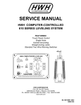
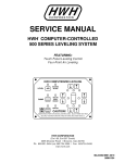
HWH JOYSTICK-CONTROLLED
200/210 SERIES LEVELING SYSTEM
R
FEATURING:
Joystick BI-AXIS Control
Kick-Down or Straight-Acting Jacks
(With or Without Air Dump)
R
HWH HYDRAULIC LEVELING
HWH HYDRAULIC LEVELING
R
ON
OPERATE
FRONT
EXTEND
NOT IN
PARK/
BRAKE
RIGHT
LEFT
DUMP
EXTEND
5 AMP
EXTEND
FUSE
REAR
EXTEND
STORE
FRONT
CAUTION!
FUSE
OFF
UNDERSTAND OPERATOR’S MANUAL BEFORE USING. BLOCK FRAME AND TIRES
SECURELY BEFORE REMOVING TIRES OR CRAWLING UNDER VEHICLE.
HWH HYDRAULIC LEVELING
ON
NOT IN
PARK/
EXTEND BRAKE
FRONT
STORE
REAR
EXTEND
EXTEND
LEFT
RIGHT
OPERATE
STORE
FRONT
EXTEND
REAR
"CAUTION"
OPERATE
UNDERSTAND OPERATOR’S MANUAL BEFORE USING.
BLOCK FRAME AND TIRES SECURELY BEFORE
REMOVING TIRES OR CRAWLING UNDER VEHICLE.
ON
OFF
CAUTION!
FUSE
5 AMP
STORE
REAR
OPERATE
UNDERSTAND OPERATOR’S MANUAL BEFORE USING.
BLOCK FRAME AND TIRES SECURELY BEFORE
REMOVING TIRES OR CRAWLING UNDER VEHICLE.
HWH CORPORATION
(On I-80, Exit 267 South)
2096 Moscow Road | Moscow, Iowa 52760
Ph: 800/321-3494 (or) 563/724-3396 | Fax: 563/724-3408
www.hwh.com
ML23934/MI91.0022
23SEP04
SECTION 1
N
TIO
SEC
1
E
UBL
O
R
T
TING
O
O
SH IDE
GU
SECTION
2
REPAIR STEPS
SEC
TION
3
DIAG
RAM
S
3 PART FOLDER
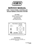
HOW TO USE MANUAL
This manual is written in three sections. Section 1 is the Trouble Shooting Guide. Section 2 is the Repair Steps. Section 3 is
the Diagrams. Begin diagnosis of the system with Section 1, the Trouble Shooting Guide. This will give the correct operation
and function of the system. When a malfunction is encountered, the Trouble Shooting Steps will direct you to the proper Repair
Steps in Section 2, the Repair Steps. The Repair Steps are broken into 3 columns, Problem, Solution, and Diagram. In the
proper part under Problems, find the symptom you have encountered. The testing and repair for that problem is in the
Solution (center) column. Diagrams for a particular Problem and Solution are in the Diagram (right hand) column. This column
will direct you to the proper diagram in Section 3, Diagrams, for a more detailed view.
NOTE: SECTION 1 is broken into three sections. HYDRAULIC OPERATION 200/210, ELECTRICAL OPERATION
200 SERIES AND ELECTRICAL OPERATION 210 SERIES. The 200 and 210 series are the same hydraulically but
electrically have some differences. Make sure you are in the proper section for the system you are working on.
Before beginning your repair, it is IMPORTANT to read the CAUTIONS and NOTES AND CHECKS in the first section,
TROUBLE SHOOTING GUIDE. In many cases this will save time and mistakes when trouble shooting a system.
This Repair Manual is offered as a guide only. It is impossible to anticipate every problem or combination of problems. This
manual is written in sequential order of the proper operation of the system. The Trouble Shooting Steps must be followed in
order to give correct diagnosis of the problem(s). For any problems encountered that are not addressed in this manual, contact
HWH Corporation for assistance.
NOTE: Diagrams in this manual are of typical systems. There may be plumbing or harness differences. In most cases
this should not effect trouble shooting procedures.
PROCEED WITH TROUBLE SHOOTING GUIDE
MI91.113D
02JAN01
TROUBLE SHOOTING
WARNING!
BLOCK FRAME AND TIRES SECURELY BEFORE CRAWLING UNDER VEHICLE. DO NOT USE THE LEVELING
JACKS OR AIR SUSPENSION TO SUPPORT VEHICLE WHILE UNDER VEHICLE OR CHANGING TIRES. VEHICLE
MAY DROP AND OR MOVE FORWARD OR BACKWARD WITHOUT WARNING CAUSING INJURY OR DEATH.
WHEN ROUTING OR REROUTING HYDRAULIC HOSES AND WIRES, BE SURE THEY ARE NOT EXPOSED TO ENGINE
EXHAUST OR ANY HIGH TEMPERATURE COMPONENTS OF THE VEHICLE.
THE JACKS MAY ABRUPTLY SWING UP WHEN THE FOOT CLEARS THE GROUND OR WHEN THE JACK REACHES
FULL EXTENSION.
NEVER PLACE HAND OR OTHER PARTS OF THE BODY NEAR HYDRAULIC LEAKS. OIL MAY CUT AND
PENETRATE THE SKIN CAUSING INJURY OR DEATH.
SAFETY CLASSES ARE TO BE WORN TO PROTECT EYES FROM DIRT, METAL CHIPS, OIL LEAKS, ECT. FOLLOW
ALL OTHER SHOP SAFETY PRACTICES.
DO NOT OVER EXTEND THE REAR JACKS. IF THE WEIGHT OF THE VEHICLE IS REMOVED FROM ONE OR BOTH
REAR WHEELS, THE VEHICLE MAY ROLL FORWARD OR BACKWARD OFF THE JACKS.
NOTES AND CHECKS
Read and check before proceeding with Trouble Shooting Steps.
NOTE: HWH CORPORATION ASSUMES NO LIABILITY
FOR DAMAGES OR INJURIES RESULTING FROM THE
INSTALLATION OR REPAIR OF THIS PRODUCT.
1. The Trouble Shooting Guide must be followed in order.
Problems checked for in one step are assumed correct and
not checked again in following steps.
2. Check that the oil reservoir is full with the jacks in the fully
retracted position.
3. Most coaches have more than one battery; one for the engine
and the other(s) for the coach. The engine battery supplies
power for the light panel and hydraulic pump. DO NOT use
the coach batteries to supply power to the pump. Batteries
under no load should read 12.6 volts. Batteries must maintain
good voltage under load. Batteries must be in good condition
with no weak cells. An alternator, converter or battery charger
will not supply enough power for the system to operate properly.
This manual is intended for use by experienced mechanics
with knowledge of hydraulic and automotive electrical
systems. People with little or no experience with HWH
leveling systems should contact HWH technical service
(800-321-3494) before beginning. Special attention should
be given to all cautions, wiring, and hydraulic diagrams.
Suggested tools for trouble shooting the HWH leveling systems:
JUMPER WIRES (UP TO 10 GAUGE)
PRESSURE GAUGE (3500 PSI MIN.)
MULTI-METER
12 VOLT TEST LIGHT
Tightening of hose ends: If tightening a new hose end, make
the hose end snug (finger tight) on the fitting, then tighten the
hose end 1/3 turn (2 FLATS). If tightening an existing hose
end, tighten the hose end to snug plus 1/4 turn (1 FLAT).
4. Proper grounding of all components is critical. See the
electrical circuit for specific grounds required. Faulty grounds,
especially for the light panel, solenoid manifold or the pump
assembly, may cause improper or erratic operation.
PROCEED WITH THE TROUBLE
SHOOTING STEPS ON THE
FOLLOWING PAGE
MI91.113F
25APR11
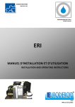
TROUBLE SHOOTING STEPS
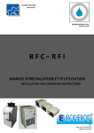
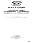
FRONT STORE LEVER
(Operate Position)
200 SERIES CONTROLS
FRONT STORE LEVER
(Store/Travel Position)
HWH HYDRAULIC LEVELING
R
OPERATE
FRONT
EXTEND
LEFT
RIGHT
EXTEND
EXTEND
STORE
FRONT
REAR
EXTEND
JACK CONTROL LEVER
STORE
REAR
REAR STORE LEVER
(Operate Position)
"CAUTION"
REAR STORE LEVER
(Store/Travel Position)
OPERATE
UNDERSTAND OPERATOR’S MANUAL BEFORE USING.
BLOCK FRAME AND TIRES SECURELY BEFORE
REMOVING TIRES OR CRAWLING UNDER VEHICLE.
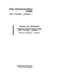
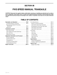
WARNING LIGHTS
(4 - Red)
POWER ON LIGHT
"ON" BUTTON
HWH HYDRAULIC LEVELING
"NOT IN PARK/BRAKE"
LIGHT
NOT IN
PARK/
BRAKE
DUMP
"DUMP" BUTTON
5 AMP
FUSE
OFF
CAUTION!
FUSE
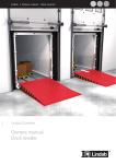
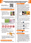
210 SERIES CONTROLS
HWH HYDRAULIC LEVELING
"ON" LIGHT
ON
NOT IN
PARK/
EXTEND BRAKE
FRONT
WARNING LIGHTS
(4 - Red)
CONTROL CIRCUIT
FUSE (5 AMP)
UNDERSTAND OPERATOR’S MANUAL BEFORE USING. BLOCK FRAME AND TIRES
SECURELY BEFORE REMOVING TIRES OR CRAWLING UNDER VEHICLE.
"OFF" BUTTON
"NOT IN
PARK/BRAKE" LIGHT
LEVELING LIGHTS
(4 - Yellow)
ON
EXTEND
EXTEND
LEFT
RIGHT
FRONT STORE LEVER
(Operate Position)
FRONT STORE LEVER
(Store/Travel Position)
OPERATE
JACK CONTROL LEVER
STORE
FRONT
EXTEND
REAR
LEVELING LIGHTS
(4 - Yellow)
"ON/OFF" SWITCH
CONTROL CIRCUIT
FUSE (5 Amp)
ON
OFF
CAUTION!
FUSE
5 AMP
STORE
REAR
REAR STORE LEVER
(Store/Travel Position)
OPERATE
UNDERSTAND OPERATOR’S MANUAL BEFORE USING.
BLOCK FRAME AND TIRES SECURELY BEFORE
REMOVING TIRES OR CRAWLING UNDER VEHICLE.
REAR STORE LEVER
(Operate Position)
HYDRAULIC OPERATION 200/210 SERIES
NOTE:If the system is not functioning electrically, proceed to the ELECTRICAL OPERATION section for 200 and 210 series.
Move the Front and Rear Store Levers to the OPERATE
position.
Turn the system ON.
1. For Kick-Down Jacks. Move the Jack Control Lever to
the EXTEND FRONT position to kick the two front jacks to the
vertical position. Move the Jack Control Lever to the EXTEND
REAR position to kick the two rear jacks to the vertical
position. If any jack(s) will not go to the vertical position see
Part 1 of the REPAIR STEPS.
2. Push the Jack Control Lever to the FRONT, REAR, RIGHT
and LEFT EXTEND positions. Two jacks should extend for
each position. The jacks should extend to the ground and lift
the vehicle. If this is not so, see Part 2 of the REPAIR STEPS.
CAUTION: If the vehicle is equipped with Kick-Down jacks do
not lift the rear of the vehicle too high. The vehicle will roll
forward or backwards if too much weight is removed from the
rear tires.
3. Move the FRONT STORE LEVER then the REAR STORE
LEVER to the Store/Travel position. If the jacks do not fully
retract, see Part 3 of the REPAIR STEPS.
MI91.113J
02JAN01
TROUBLE SHOOTING STEPS
ELECTRICAL OPERATION - 200 SERIES
4. With the ignition off no lights on the light panel should
be on. If this is not so see Part 4 of the REPAIR STEPS.
5. With the ignition in the "ACC" or "ON" position and the
Light Panel off, no lights on the light panel should be on.
If this is not so see Part 5 of the REPAIR STEPS.
6. Push the "ON" button. The Power On light should be
on. One Yellow Leveling Light may be on. If this is not
correct or other lights are on, see Part 6 of the REPAIR
STEPS.
7. Move the STORE LEVERS to the Operate Position.
Push the JACK CONTROL LEVER to the four EXTEND
positions to check the correct function of the jacks. The
pump should run when the JACK CONTROL LEVER is
pushed to all four positions. The pump should turn off when
the JACK CONTROL LEVER returns to the center position.
The red Warning Lights should come on as their respective
jacks go to the vertical position (Kick-Down Jacks) or have
extended between 1 and 2 inches (Straight-Acting Jacks).
The Master Warning Light should be on. If the vehicle is
equipped with Straight-Acting Jacks, there should be a buzzer
that is on, if the ignition is in the "ON" position. If any of this
is not so, see Part 7 of the REPAIR STEPS.
8. Air dump check. The "DUMP" button is a momentary
button. The "DUMP" button will only work with the panel on.
Push and hold the "DUMP’ button, the air should exhaust
from the vehicles suspension. Release the "DUMP" button.
The vehicle should return to the proper ride height. If any of
this does not happen, see Part 8 of the REPAIR STEPS.
NOTE: The vehicle engine will have to be running for the
vehicle to return to ride height.
9. Level sensing unit check. Extend the jacks to the ground
and put the coach in a level position. All yellow lights should
be out. If a yellow light is on, adjust the sensing unit. Check
that the sensing unit is positioned properly and mounted to a
solid surface. If the sensing unit cannot be adjusted, yellow
lights never come on or more than one yellow light comes on
at a time, see Part 9 of the REPAIR STEPS.
10. Move the STORE LEVERS to the STORE position.
As the jacks retract to the stored position, their respective
red warning lights should go out and the master warning
indicators should turn off when all four red warning lights are
out. If this is not so, see Part 10 of the REPAIR STEPS.
ELECTRICAL OPERATION - 210 SERIES
11. With the ignition off no lights on the light panel should
be on. If this is not so see Part 11 of the REPAIR STEPS.
12. With the ignition in the "ACC" or "ON" position and
the Light Panel off, there should be no lights on unless a
jack is in the vertical position or extended. The four red
warning lights will work if the panel is off and the ignition is
on. If the lights are not working properly, see Part 12 of the
REPAIR STEPS.
13. Push the ON/OFF rocker switch to the "ON" postion.
The Power On Light should be on. One Yellow Level Light
may be on. If this is not correct, or other lights are on, see
Part 13 of the REPAIR STEPS.
14. Move the STORE LEVERS to the Operate Position.
Push the JACK CONTROL LEVER to the four EXTEND
positions to check the correct function of the jacks. The
pump should run when the JACK CONTROL LEVER is
pushed to all four positions. The pump should turn off when
the JACK CONTROL LEVER returns to the center position.
The red Warning Lights should come on as their respective
jacks go to the vertical position (Kick-Down Jacks) or have
extended between 1 and 2 inches (Straight-Acting Jacks).
The Master Warning Light should be on. If the vehicle is
equipped with Straight-Acting Jacks, there should be a buzzer
that is on, if the ignition is in the "ON" position. If any of this
is not so, see Part 14 of the REPAIR STEPS.
15. Air dump check. The "DUMP" switch is a momentary
switch. The "DUMP" switch will only work with the panel on.
Push and hold the "DUMP’ switch, the air should exhaust
from the vehicles suspension. Release the "DUMP" switch
The vehicle should return to the proper ride height. If any of
this does not happen, see Part 15 of the REPAIR STEPS.
NOTE: The vehicle engine will have to be running for the
vehicle to return to ride height.
16. Level sensing unit check. Extend the jacks to the
ground and put the coach in a level position. All yellow lights
should be out. If a yellow light is on, adjust the sensing unit.
Check that the sensing unit is positioned properly and
mounted to a solid surface. If the sensing unit cannot be
adjusted, yellow lights never come on or more than one yellow
light comes on at a time, see Part 16 of the REPAIR STEPS.
17. Move the STORE LEVERS to the STORE position.
As the jacks retract to the stored position, their respective
red warning lights should go out and the master warning
indicators should turn off when all four red warning lights are
out. If this is not so, see Part 17 of the REPAIR STEPS.
NOTE: A test harness for the 210 system is available from
HWH. Due to the design of the system and the type of
connector plugs used, some tests are hard to perform with
out this test harness. Contact HWH Customer Service to
obtain a test harness.
MI91.113M
02JAN01
SECTION 2
REPAIR MANUAL
HWH JOY STICK - CONTROLLED
LEVELING SYSTEMS
200/210 SERIES
FEATURING:
JOY STICK BI - AXIS CONTROL
KICK - DOWN JACKS
STRAIGHT - ACTING JACKS
MANUAL AIR DUMP
BEGIN WITH SECTION 1
MI91.233C
07MAR01
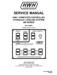
REPAIR STEPS
PROBLEM
SOLUTION
FRONT
Part 1
When the Jack
Control Lever
is moved to the
FRONT or REAR
EXTEND
positions:
FIGURES
PRESSURE
RETURN
LF
RF
PRESSURE
RIGHT FRONT
JACK
LEFT FRONT
JACK
RETURN
a: The jacks
will not go
vertical. The
pump runs
under no load.
Remove the return line from the pump and direct the line into a
container. Try to extend the jacks. There should be no fluid flowing
from the return line.
If fluid flows from the return line, the valve is the problem. Check
that the bezel or light plate is positioned properly. If the plate is out
of position, it can keep a STORE LEVER from being in the Operate
Position properly. If the plate is positioned properly, replace the valve
LEFT REAR
JACK
LR
FRONT
Remove he pressure line from the pump and attach a pressure
gauge to the pump fitting. Run the pump. Pump pressure should
be between 3200 and 3600 PSI. If the pump pressure is bad,
replace the pump.
RR
REFER TO MP65
If no fluid flows from the return line the pump should be replaced.
b: One or more
jacks will not go
vertical. The
pump runs
under load.
RIGHT REAR
JACK
PRESSURE
RETURN
LF
If the pump pressure is OK, remove the line from the jack(s) that
will not kick down. Try to Extend the jack(s). If there is a good flow
of fluid, the problem is at the jack. Check that the jack can be pulled
vertical easily. Check that the roller bearings are free. Check that
the actuator cables, rods and horizontal stops are in place. Make
sure hoses or wires are not restricting the movement of the jack. If
everything is OK, replace the actuator.
If no fluid is flowing from the hose at the jack, remove that hose from
the valve and retry. If no fluid comes out of the valve the valve is the
problem. If fluid flows from the valve the hose is the problem.
RF
PRESSURE
RIGHT FRONT
JACK
LEFT FRONT
JACK
RETURN
LEFT REAR
JACK
RIGHT REAR
JACK
LR
RR
REFER TO MP65
If no jacks will go vertical and no fluid is coming out of the valve,
remove the pressure line from the valve and retry. If fluid flows from
the valve, check that the hoses are connected to the correct outputs
at the valve. If no fluid comes from the hose, the hose or fittings are
the problem.
NOTE: Any fitting (especially 90DEG fittings) may not be made
properly and will not flow fluid.
c: One front or
rear jack will go
vertical, extend
to the ground
and lift the
vehicle more
than 1 to 1-1/2"
before the other
jack goes
vertical or goes
vertical and
starts to extend.
NOTE: This is
for 6000# and
9000# jacks only.
As long as one jack does not lift the vehicle more than approximately
1-1/2 inches, that is within the tolerance of the actuator.
6000# JACK
REFER TO MP65.3030
Make sure the jacks swing freely and are not abstructed from moving.
Apply some oil where the springs pivot around the jack. Adjust the
horizontal adjustment of the slow jack, so it hangs slightly lower than
the other jack.
9000# JACK
REFER TO MP65.3035
16000# JACK
REFER TO MP65.3040
Make sure the valve cover plate is mounted correctly over the valve.
Moving the Jack Control Lever closer to one side of the slot can
direct more fluid to one jack.
MI91.233E
02JAN01
REPAIR STEPS
PROBLEM
Part 1
Continued
SOLUTION
FIGURES
There is no way to determine which actuator is the problem without
a pressure gauge. Replace the slow actuator first. If that does not
fix the problem, replace the fast actuator with the actuator that was
removed.
If a pressure gauge is available, tee the gauge between the hose
and actuator at the jack on the jack that is faster. Starting from fully
retracted, operate the jacks. Watch the jack and gauge closely.
The pressure should be greater than 1050 PSI, but never exceed
1300 PSI. as the jack swings vertical, just before the foot of the jack
starts to extend. If the actuator being checked is within the above
limits, replace the other actuator.
d: The foot of a
jack extends
but the jack will
not go vertical.
Check that rollers or actuator cables or rods are not missing. Check
that horizontal stops are in the proper location. If everything is OK,
replace the actuator.
e: A jack swings
vertical but will
not extend.
Do this test with the jack in the vertical position. On a 9000# jack,
take the tube between the actuator and the jack loose at the jack. On
a 16,000# or 6000# jack loosen the actuator from the jack. Leave the
hose attached. Try to extend the jack. If fluid comes out of the tube
or from between the actuator and jack, replace the complete jack.
If no fluid comes out, replace the actuator.
6000# JACK
REFER TO MP65.3030
9000# JACK
REFER TO MP65.3035
16000# JACK
REFER TO MP65.3040
a: The wrong
jacks extend.
The hoses are not connected to the correct output at the valve.
Refer to the Hydraulic Line Connection Diagram for correct
connection information.
FRONT
Part 2
When the Jack
Control Lever
is pushed to an
extend position:
PRESSURE
RETURN
LF
RF
PRESSURE
b: For StraightActing Jacks.
The jacks will
not extend, the
pump runs
under no load.
Remove the return line from the pump and direct it into a container.
Try to extend the jacks.
If fluid flows from the return line. The valve is the problem. Check
that the bezel or light plate is positioned on the valve properly. If
the plate is positioned incorrectly, it can keep a STORE LEVER from
being in the Operate Position properly. If the plate is positioned
properly, replace the valve.
LEFT FRONT
JACK
RIGHT FRONT
JACK
RETURN
LEFT REAR
JACK
RIGHT REAR
JACK
LR
RR
If no fluid flows from the return line, replace the pump.
REFER TO MP65
c: For StraightActing Jacks.
One or more
jacks will not
extend, the
pump is running
under load.
If no jacks will extend, remove the pressure line from the pump and
attach a pressure gauge to the pump fitting. Run the pump. Pump
pressure should be between 3200 and 3600 PSI. If the pump
pressure is bad, replace the pump. If pump pressure is OK, reattach
the pressure line to the pump. Make sure there is fluid flowing to the
valve. The pressure line or fittings may have a problem.
MI91.233G
02JAN01
REPAIR STEPS
Part 2
Continued
SOLUTION
If one or more jacks will extend and lift the vehicle, there should be
enough pressure to extend all of the jacks. Make sure the tank is full
of fluid with the jacks fully retracted. Remove the line from the jack(s)
that will not extend. Try to extend the jacks. If there is a good flow
of fluid to the jack, replace the jack cylinder. If there is no fluid flow
from the hose, remove the hose at the valve. If there is flow out at
the valve, the problem is the hose. If there is no flow from the valve,
replace the valve.
FIGURES
FRONT
PROBLEM
PRESSURE
RETURN
LF
RF
PRESSURE
NOTE: Any fittings (especially 90DEG fittings) may not be made
properly and will not flow fluid.
d: One or more
jacks will extend
to the ground
but will not lift
the vehicle.
Check the fluid level in the tank. Remove the pressure line from the
pump and attach a pressure gauge to the pump fitting. Run the
pump. Pump pressure should be between 3200 and 3600 PSI. If
pump pressure is bad, replace the pump.
If pump pressure is OK, check the return line. If fluid is flowing from
the return line while trying to extend a jack, the problem is the valve.
Make sure the bezel or light plate is positioned properly. If the plate
is OK, replace the valve.
LEFT FRONT
JACK
RIGHT FRONT
JACK
RETURN
LEFT REAR
JACK
RIGHT REAR
JACK
LR
RR
REFER TO MP65
If fluid is not flowing through the return line, check the pressure in the
line at the jack. The problem is probably the jack or the cylinder.
e: The jacks
will not lift the
vehicle far
enough to
level it.
The jacks may have reached full extension. The following are the
measurements for jack extension:
6000# Short KICK-DOWN AP7129 - 7 INCHES
6000# Tall KICK-DOWN AP7164 - 8 INCHES
9000# Short KICK-DOWN AP7001 - 8-1/2 INCHES
9000# Tall KICK-DOWN AP7002 - 9 INCHES
16000# KICK-DOWN AP2381 - 8 INCHES
The following are suggested ground clearances with jacks vertical
but not extended:
6000# KICK-DOWN - 2" to 4"
9000# KICK-DOWN - 3" to 4-1/2"
16000# KICK-DOWN - 2" to 4"
All Straight-Acting jacks have a stroke of either 13 inches or
16 inches with a retracted clearance of 8 inches. Vehicles with air
suspension will have several more inches of clearance with the air
bags full.
Make sure the pump has pump pressure between 3200 and
3600 PSI.
Make sure the jack capacity is enough to handle the axle weights
of the vehicle.
f: When one
jack has
extended fully
the other jack
will not extend
any more.
One jack may not have the capacity to lift the vehicle any further by
itself. This is not a problem. The system is designed to always use
two jacks for lifting. One jack lifting by itself may twist the vehicle.
MI91.233J
02JAN01
REPAIR STEPS
PROBLEM
SOLUTION
FIGURES
Part 2
Continued
g: A jack will
retract by itself
after being
extended to
the ground.
An excessive visible oil leak for that jack can allow the jack to
retract.
If there is no major oil leak, the valve is leaking internally and should
be replaced.
Part 3
After moving
the STORE
LEVERS to the
Store/Travel
position:
CAUTION: The vehicle should be properly supported before
performing tasks which require being under the vehicle.
Releasing fluid from the jacks will cause the vehicle to drop
and possibly move forward or backward causing injury or
death.
FRONT
NOTE: If a jack is retracting less than 1/2" the problem is
thermal contraction of the fluid. There is no repair for this.
The jacks need to be extended to lift the vehicle at least 3/4"
when stabilizing the vehicle.
PRESSURE
RETURN
LF
RF
PRESSURE
LEFT FRONT
JACK
RIGHT FRONT
JACK
RETURN
Kick-Down
Jacks
a: A jack will
not retract at
all.
Take the hose loose at the jack. If the foot retracts into the jack and
swings to the horizontal position, the problem is in the hose or the
valve. Extend the jack. Remove the hose for that jack at the valve.
If the jack retracts, the valve should be replaced. If the jack does
not retract, the hose is the problem. Check for kinks.
If the jack does not retract with the hose removed. The problem is
the jack cylinder or the actuator. On a 9000# jack, loosen the tube
between the jack and the actuator. On 6000# and 16000# jacks,
loosen the actuator from the jack. If the cylinder retracts, replace
the actuator. If the cylinder stays extended, replace the complete
jack.
b: The foot of
the jack retracts
but the jack will
not swing to the
horizontal
position.
Make sure the jack can pivot. Check if springs, rollers, actuator
cables and rods are OK. If these things are OK, replace the
actuator.
c: The jack
starts to retract,
swings to the
horizontal
position but the
foot will not
retract fully
into the cylinder.
Check the hose for a kink at the jack. Loosen the actuator tube on
9000# jacks or loosen the actuator on the 6000# or 16000# jacks.
If the foot finishes retracting, replace the actuator. If the foot stays
extended, replace the complete jack.
d: Stright-Acting
jacks. A jack will
not retract at all
or will not fully
retract.
Take the hose loose at the jack, if it doesn’t retract, replace the
cylinder. If it does retract, loosen the hose for that jack at the valve.
If the jack retracts, replace the valve. If the jack does not retract, the
problem is the hose.
NOTE: Lubricating jack cylinder rods or actuator rods is not
necessary. Lubricating rods may improve operation temporarily
but will not fix the problem.
LEFT REAR
JACK
RIGHT REAR
JACK
LR
RR
REFER TO MP65
6000# JACK
REFER TO MP65.3030
9000# JACK
REFER TO MP65.3035
16000# JACK
REFER TO MP65.3040
6000# JACK
REFER TO MP65.3030
9000# JACK
REFER TO MP65.3035
16000# JACK
REFER TO MP65.3040
6000# JACK
REFER TO MP65.3030
9000# JACK
REFER TO MP65.3035
16000# JACK
REFER TO MP65.3040
REFER TO MP65
MI91.233M
02JAN01
REPAIR STEPS
PROBLEM
SOLUTION
FIGURES
Part 3
Continued
Any Jack
e: A jack
retracts slowly.
For Kick-Down jacks refer to Part 3a and for Straight-Acting jacks
refer to Part 3d.
f: no jacks will
retract.
Take the return line loose from the pump. Try to retract. If the jacks
retract the problem is the pump or pump fitting for the return line. If
the jacks do not retract, take the return line loose at the valve. If the
jacks retract the return line is the problem. If the jacks still will not
retract, refer to Part 3a for Kick-Down jacks and Part 3d for StraightActing jacks.
REFER TO MP65
ELECTRICAL DIAGNOSTICS - 200 SERIES
PANEL CONNECTION DIAGRAM
5-PIN MTA
SENSING UNIT
a: A light on the
light panel is on.
REAR RED
RIGHT SIDE GREEN
FRONT BLACK
LEFT SIDE YELLOW
GROUND WHITE
4-PIN MTA
PARK/BRAKE
There should be no power to the Light Panel. Trace the 6120 (RED)
wire to it’s source. It should be connected to the "ACC" side of the
ignition switch.
11-PIN MTA
HARNESS
GROUND - (WHITE) 6230
PUMP - (BLUE) 6820
- WARN. LIGHT - (BROWN) 7699
+ WARN. LIGHT - (PURPLE) 6121
LEFT REAR - (GREEN) 4000
LEFT FRONT - (ORANGE) 1000
RIGHT FRONT - (GRAY) 2000
RIGHT REAR - (BLACK) 3000
NOT USED
AIR DUMP - (YELLOW) 9300
AIR DUMP - (YELLOW) 9301
WIRING HARNESS
Part 4
With the
ignition switch
off:
NOTE: THE (4) DIGIT WIRE
NUMBER SUPERSEDES
ANY AND ALL WIRE COLORS.
(BLUE)
9000
FUSED +12 ACC. POWER
15A. MAX. - (RED) 6120
REFER TO MP85.1520
Part 5
With the
ignition in the
"ON" or "ACC"
position:
a: The Power
On Light is lit.
Push the "OFF" button. If the light does not go out, replace the light
panel.
b: Lights other
than the Power
On Light are on.
No lights should be on, replace the panel.
c: The panel is
off but the
master warning
light and
buzzer, if so
equipped, is on.
No jacks are
vertical or
extended.
Push the "ON" button. One or more red warning lights should be on.
PANEL CONNECTION DIAGRAM
5-PIN MTA
SENSING UNIT
REAR RED
RIGHT SIDE GREEN
FRONT BLACK
LEFT SIDE YELLOW
GROUND WHITE
If no red warning lights on the panel are on, remove the 7699
(BROWN) wire from the MTA plug (9 or 11 pin). If the light goes out,
replace the light panel. If the light does not go out, the 7699
(BROWN) wire is shorted to ground.
11-PIN MTA
HARNESS
GROUND - (WHITE) 6230
PUMP - (BLUE) 6820
- WARN. LIGHT - (BROWN) 7699
+ WARN. LIGHT - (PURPLE) 6121
LEFT REAR - (GREEN) 4000
LEFT FRONT - (ORANGE) 1000
RIGHT FRONT - (GRAY) 2000
RIGHT REAR - (BLACK) 3000
NOT USED
AIR DUMP - (YELLOW) 9300
AIR DUMP - (YELLOW) 9301
WIRING HARNESS
4-PIN MTA
PARK/BRAKE
NOTE: THE (4) DIGIT WIRE
NUMBER SUPERSEDES
(BLUE)
9000
ANY AND ALL WIRE COLORS.
FUSED +12 ACC. POWER
15A. MAX. - (RED) 6120
REFER TO MP85.1520
PUMP RELAY HARNESS
HWH HYDRAULIC LEVELING
6230
OPERATE
FRONT
RAISE
LEFT
SEE PUMP RELAY
CONNECTION DIAGRAM
BA
RIGHT
RAISE
RAISE
REAR
RAISE
STORE
FRONT
8600
(BLUE) 9000
STORE
REAR
"CAUTION"
HWH HYDRAULIC LEVELING
SEE PANEL
CONNECTION
DIAGRAM
OPERATE
UNDERSTAND OPERATOR’S MANUAL BEFORE USING.
BLOCK FRAME AND TIRES SECURELY BEFORE
REMOVING TIRES OR CRAWLING UNDER VEHICLE.
MASTER WARNING
LIGHT/BUZZER
CONNECTION DIAGRAM
TO BRAKE
LIGHT ON
DASH - 9001
WIRES ARE
LABELED
ON
NOT IN
PARK/
BRAKE
5 AMP
FUSE
OFF
CAUTION!
FUSE
If a red warning light on the panel is on, the master warning light and
buzzer should be on. Unplug the warning switch for the warning
light that is on. If the light goes out replace the warning switch.
UNDERSTAND OPERATOR’S MANUAL BEFORE USING. BLOCK FRAME AND TIRES
SECURELY BEFORE REMOVING TIRES OR CRAWLING UNDER VEHICLE.
FROM +12 ACC
FUSE 15 AMP MAX (RED) 6120
TO PARK
BRAKE SWITCH
(YELLOW)
9300
RF
LF
BA
BA
(WHITE)
6230
(WHITE) 6230
(ORANGE)
1000
WARNING
SWITCH
WARNING
SWITCH
SENSING
UNIT
AIR DUMP
VALVE
BA
OTHER AIR DUMP
VALVE ARRANGEMENTS
ARE POSSIBLE
BA
(YELLOW)
9301
NOTE: SEE SUSPENSION AIR
DUMP DIAGRAM FOR ADDITIONAL
EXPLANATION OF AIR DUMP
VALVE CONNECTIONS (WHITE) 6230
(WHITE)
6230
(GREEN)
4000
BA
WARNING
SWITCH
(BLACK)
3000
(WHITE)
6230
BA
LR
(WHITE)
6230
DO NOT REVERSE WIRE
COLORS TO A & B ON
PACKARD CONNECTORS
BA
NOTE: If it is a new system check that the wires are in the plugs
in the correct position. The white wire should be in the A side
of the plug and the black (or colored) wire should be in the B
side of the plug.
BA
(GRAY)
2000
NOTE: THE (4) DIGIT WIRE
NUMBER SUPERSEDES ANY
AND ALL WIRE COLORS.
RR
WARNING
SWITCH
REFER TO MP85.1515
MI91.233P
02JAN01
REPAIR STEPS
PROBLEM
Part 5
Continued
SOLUTION
FIGURES
If replacing the switch does not fix the problem and the vehicle has
Straight Acting jacks, there could be a problem with the magnet in
the jack.
If the warning light does not go out when the switch is unplugged,
remove the correct numbered (or colored) wire from the MTA plug
(9 or 11 pin). If the light goes out, the wire is shorted to ground. If
the light does not go out, replace the light panel.
Part 6
With the ignition
on, push the
"ON" button on
the light panel:
Turn the ignition OFF. Check the 5AMP fuse in the light panel.
PUMP RELAY CONNECTION DIAGRAM
PUMP MUST BE MOUNTED SOLIDLY TO FRAME. SOME PUMPS HAVE A
GROUND CABLE THAT IS TO BE ATTACHED TO THE GROUND STUD.
WIRE
FROM HARNESS (BLUE) 6820
3
4
BATTERY
-
1
2
8600
* FUSE
GROUND
FROM VALVE
6230
WIRES ARE LABELED
DO NOT REVERSE
NOTE: IF THE PUMP BRACKET IS WELDED TO THE
FRAME, USE THE GROUND STUD TO ATTACH THE
PUMP TO THE BRACKET. IF THE PUMP BRACKET IS
BOLTED TO THE FRAME, USE THE GROUND STUD TO
ATTACH THE BRACKET TO THE FRAME.
NOTE: THE (4) DIGIT
WIRE NUMBER
SUPERSEDES ANY
AND ALL WIRE
COLORS.
GROUND STUD
FROM HARNESS
FUSED 10A (WHITE) 6230
* FUSE MAY BE REQUIRED - CHECK APPLICABLE CODE
PANEL CONNECTION DIAGRAM
5-PIN MTA
SENSING UNIT
REAR RED
RIGHT SIDE GREEN
FRONT BLACK
LEFT SIDE YELLOW
GROUND WHITE
4-PIN MTA
PARK/BRAKE
11-PIN MTA
HARNESS
GROUND - (WHITE) 6230
PUMP - (BLUE) 6820
- WARN. LIGHT - (BROWN) 7699
+ WARN. LIGHT - (PURPLE) 6121
LEFT REAR - (GREEN) 4000
LEFT FRONT - (ORANGE) 1000
RIGHT FRONT - (GRAY) 2000
RIGHT REAR - (BLACK) 3000
NOT USED
AIR DUMP - (YELLOW) 9300
AIR DUMP - (YELLOW) 9301
WIRING HARNESS
If the fuse is OK, turn the ignition to "ACC" or "ON" and check the
6120 (RED) wire for +12 volts at the fuse. If +12 volts is not
present, trace the 6120 (RED) wire to it’s source and repair. If the
6120 (RED) wire is fused and the fuse is blown, the 6120 (RED)
wire is probably shorted to ground. If +12 volts is present on the
6120 (RED) wire at the 5AMP fuse, make sure connections are
good, tight and not corroded. Make sure there is a good ground on
the 6230 (WHITE) wire in the (9 or 11 pin) MTA plug. Make sure
the 6230 (WHITE) wire is pushed in the connector properly. If there
is good voltage and ground to the panel, replace the panel.
+
a: The Power
On light will not
come on. No
other lights
come on.
NOTE: THE (4) DIGIT WIRE
NUMBER SUPERSEDES
ANY AND ALL WIRE COLORS.
(BLUE)
9000
If the 5AMP fuse in the panel is blown, replace the fuse. Turn
the ignition to "ON" or "ACC". If the fuse blows right away, check
the 6121 (PURPLE) wire going to the Master Warning Light. That
wire may be shorted to ground. Some systems may not use that
wire. If that wire is not used or is not shorted, replace the panel.
FUSED +12 ACC. POWER
15A. MAX. - (RED) 6120
REFER TO MP85.1520
If the fuse does not blow when the ignition is turned ON, push the
"ON" button. If the fuse does not blow, continue operating the
system. If the fuse blows, the problem is the pump relay, the 6820
(BLUE) wire or the panel. Remove the 6820 (BLUE) wire from the
pump relay. Replace the fuse. If the fuse does not blow replace the
relay. If the fuse blows, remove the 6820 (BLUE) wire from the
(9 or 11 pin) MTA plug. Replace the fuse. Push the "ON" button.
If the fuse does not blow, the 6820 (BLUE) wire is shorted to ground.
If the fuse blows, replace the light panel.
PUMP RELAY HARNESS
HWH HYDRAULIC LEVELING
BA
RAISE
REAR
RAISE
STORE
FRONT
8600
(BLUE) 9000
STORE
REAR
HWH HYDRAULIC LEVELING
SEE PANEL
CONNECTION
DIAGRAM
OPERATE
NOT IN
PARK/
BRAKE
5 AMP
FUSE
OFF
CAUTION!
UNDERSTAND OPERATOR’S MANUAL BEFORE USING. BLOCK FRAME AND TIRES
SECURELY BEFORE REMOVING TIRES OR CRAWLING UNDER VEHICLE.
FROM +12 ACC
FUSE 15 AMP MAX (RED) 6120
TO PARK
BRAKE SWITCH
(YELLOW)
9300
RF
LF
BA
BA
(WHITE)
6230
(WHITE) 6230
(ORANGE)
1000
WARNING
SWITCH
AIR DUMP
VALVE
(WHITE)
6230
DO NOT REVERSE WIRE
COLORS TO A & B ON
PACKARD CONNECTORS
BA
BA
OTHER AIR DUMP
VALVE ARRANGEMENTS
ARE POSSIBLE
BA
(YELLOW)
9301
NOTE: SEE SUSPENSION AIR
DUMP DIAGRAM FOR ADDITIONAL
EXPLANATION OF AIR DUMP
VALVE CONNECTIONS (WHITE) 6230
(WHITE)
6230
(GREEN)
4000
BA
WARNING
SWITCH
(BLACK)
3000
(WHITE)
6230
BA
LR
BA
(GRAY)
2000
WARNING
SWITCH
SENSING
UNIT
If there is a ground on the 9000 (BLUE) wire, make sure that wire
and the small jumper wire is pushed into the MTA connector properly.
Check voltage at the panel between the 6120 (RED) wire and the
9000 (BLUE) wire while pushing the "ON" button. If the voltage is
less than 9 volts, the panel will not turn on. Check all connections
on both wires, a poor ground on the 9000 (BLUE) wire can cause low
voltage for the panel. At least +9 volts is needed to turn the panel on.
If the voltage is greater than 9 volts, replace the panel.
TO BRAKE
LIGHT ON
DASH - 9001
WIRES ARE
LABELED
ON
FUSE
"CAUTION"
UNDERSTAND OPERATOR’S MANUAL BEFORE USING.
BLOCK FRAME AND TIRES SECURELY BEFORE
REMOVING TIRES OR CRAWLING UNDER VEHICLE.
MASTER WARNING
LIGHT/BUZZER
CONNECTION DIAGRAM
If the park brake is set, check the 9000 (BLUE) wire in the 4 pin
MTA plug at the panel for a ground. If there is no ground, the 9000
(BLUE) wire or the park brake switch is the problem.
SEE PUMP RELAY
CONNECTION DIAGRAM
RIGHT
RAISE
Make sure the park brake is set. If not, set the brake and retry.
6230
OPERATE
FRONT
RAISE
LEFT
b: The NOT IN
PARK/BRAKE
light comes on
when the "ON"
button is
pushed. No
other lights
come on. The
NOT IN PARK/
Brake light
goes out when
the "ON" button
is released.
NOTE: THE (4) DIGIT WIRE
NUMBER SUPERSEDES ANY
AND ALL WIRE COLORS.
RR
WARNING
SWITCH
REFER TO MP85.1515
MI91.233R
02JAN01
REPAIR STEPS
SOLUTION
Part 6
Continued
FIGURES
PUMP RELAY HARNESS
HWH HYDRAULIC LEVELING
6230
OPERATE
FRONT
RAISE
RAISE
STORE
FRONT
REAR
RAISE
8600
(BLUE) 9000
STORE
REAR
HWH HYDRAULIC LEVELING
SEE PANEL
CONNECTION
DIAGRAM
OPERATE
"CAUTION"
UNDERSTAND OPERATOR’S MANUAL BEFORE USING.
BLOCK FRAME AND TIRES SECURELY BEFORE
REMOVING TIRES OR CRAWLING UNDER VEHICLE.
MASTER WARNING
LIGHT/BUZZER
CONNECTION DIAGRAM
NOT IN
PARK/
BRAKE
5 AMP
FUSE
OFF
CAUTION!
UNDERSTAND OPERATOR’S MANUAL BEFORE USING. BLOCK FRAME AND TIRES
SECURELY BEFORE REMOVING TIRES OR CRAWLING UNDER VEHICLE.
FROM +12 ACC
FUSE 15 AMP MAX (RED) 6120
Unplug the warning switch for the jack warning light that is on. If the
light goes out, replace the warning switch.
TO BRAKE
LIGHT ON
DASH - 9001
WIRES ARE
LABELED
ON
TO PARK
BRAKE SWITCH
(YELLOW)
9300
RF
LF
BA
BA
(WHITE)
6230
(WHITE) 6230
(ORANGE)
1000
NOTE: If it is a new system check that the white wire is in the A side
of the plug and that the black (colored) wire is in the B side of the
plug. If the light comes on after replacing the warning switch, if it is
a straight acting jack the magnet in the jack may be the problem.
(WHITE)
6230
WARNING
SWITCH
WARNING
SWITCH
DO NOT REVERSE WIRE
COLORS TO A & B ON
PACKARD CONNECTORS
SENSING
UNIT
AIR DUMP
VALVE
BA
OTHER AIR DUMP
VALVE ARRANGEMENTS
ARE POSSIBLE
BA
(YELLOW)
9301
(WHITE)
6230
NOTE: SEE SUSPENSION AIR
DUMP DIAGRAM FOR ADDITIONAL
EXPLANATION OF AIR DUMP
VALVE CONNECTIONS (WHITE) 6230
(BLACK)
3000
(WHITE)
6230
(GREEN)
4000
LR
RR
BA
If the warning light does not go out after unplugging the warning
switch, the black numbered wire (or colored wire) in the harness is
the problem. Remove the correct wire from the (9 or 11 pin) MTA
plug. If the light goes out, the wire is shorted to ground. If the
warning light still does not go out, replace the light panel.
BA
(GRAY)
2000
BA
BA
c: A red warning
light is on, no
jacks are
vertical or
extended.
SEE PUMP RELAY
CONNECTION DIAGRAM
RIGHT
RAISE
BA
LEFT
FUSE
PROBLEM
NOTE: THE (4) DIGIT WIRE
NUMBER SUPERSEDES ANY
AND ALL WIRE COLORS.
WARNING
SWITCH
WARNING
SWITCH
REFER TO MP85.1515
PANEL CONNECTION DIAGRAM
e: The pump
runs when the
"ON" button
is pushed.
The valve switch completes a ground circuit to operate the pump.
Remove the bezel plate from the valve. Make sure the valve is
clean. Screws, coins, nails, any metal object down inside the valve
can short the jack control lever to the valve switch plate. This would
start the pump. If the valve is clean, the 8600 (BLACK) wire going
to the pump relay is shorted to ground or the valve switch plate is
grounded. Unplug the two wire plug at the valve, if the pump
continues to run the 8600 (BLACK) wire is shorted to ground. If the
pump does not run, replace the valve.
5-PIN MTA
SENSING UNIT
REAR RED
RIGHT SIDE GREEN
FRONT BLACK
LEFT SIDE YELLOW
GROUND WHITE
4-PIN MTA
PARK/BRAKE
11-PIN MTA
HARNESS
GROUND - (WHITE) 6230
PUMP - (BLUE) 6820
- WARN. LIGHT - (BROWN) 7699
+ WARN. LIGHT - (PURPLE) 6121
LEFT REAR - (GREEN) 4000
LEFT FRONT - (ORANGE) 1000
RIGHT FRONT - (GRAY) 2000
RIGHT REAR - (BLACK) 3000
NOT USED
AIR DUMP - (YELLOW) 9300
AIR DUMP - (YELLOW) 9301
NOTE: THE (4) DIGIT WIRE
NUMBER SUPERSEDES
ANY AND ALL WIRE COLORS.
(BLUE)
9000
FUSED +12 ACC. POWER
15A. MAX. - (RED) 6120
REFER TO MP85.1520
6230
HWH HYDRAULIC LEVELING
OPERATE
FRONT
RAISE
LEFT
RIGHT
RAISE
RAISE
BA
Unplug the sensing unit from the light panel. If the yellow lights
remain on, replace the light panel. If the yellow lights go out, use a
test light to ground the four pins on the panel one at a time. If a
yellow light does not come on, or more than one yellow light comes
on or the correct yellow light does not come on, replace the panel.
If the lights work correctly, replace the sensing unit.
WIRING HARNESS
d: More than
one yellow
level light is on
or opposing
yellow lights
are on.
STORE
FRONT
REAR
RAISE
8600
STORE
REAR
OPERATE
"CAUTION"
UNDERSTAND OPERATOR’S MANUAL BEFORE USING.
BLOCK FRAME AND TIRES SECURELY BEFORE
REMOVING TIRES OR CRAWLING UNDER VEHICLE.
REFER TO MP85.1515
PANEL CONNECTION DIAGRAM
Part 7
When the JACK
CONTROL
LEVER is moved
to the EXTEND
positions to
operate the
jacks:
5-PIN MTA
SENSING UNIT
REAR RED
RIGHT SIDE GREEN
FRONT BLACK
LEFT SIDE YELLOW
GROUND WHITE
WIRING HARNESS
4-PIN MTA
PARK/BRAKE
11-PIN MTA
HARNESS
GROUND - (WHITE) 6230
PUMP - (BLUE) 6820
- WARN. LIGHT - (BROWN) 7699
+ WARN. LIGHT - (PURPLE) 6121
LEFT REAR - (GREEN) 4000
LEFT FRONT - (ORANGE) 1000
RIGHT FRONT - (GRAY) 2000
RIGHT REAR - (BLACK) 3000
NOT USED
AIR DUMP - (YELLOW) 9300
AIR DUMP - (YELLOW) 9301
NOTE: THE (4) DIGIT WIRE
NUMBER SUPERSEDES
(BLUE)
9000
ANY AND ALL WIRE COLORS.
FUSED +12 ACC. POWER
15A. MAX. - (RED) 6120
REFER TO MP85.1520
PUMP RELAY HARNESS
HWH HYDRAULIC LEVELING
6230
OPERATE
FRONT
RAISE
SEE PUMP RELAY
CONNECTION DIAGRAM
RIGHT
BA
LEFT
RAISE
RAISE
REAR
RAISE
STORE
FRONT
8600
(BLUE) 9000
STORE
REAR
NOT IN
PARK/
BRAKE
5 AMP
FUSE
OFF
CAUTION!
UNDERSTAND OPERATOR’S MANUAL BEFORE USING. BLOCK FRAME AND TIRES
SECURELY BEFORE REMOVING TIRES OR CRAWLING UNDER VEHICLE.
FROM +12 ACC
FUSE 15 AMP MAX (RED) 6120
TO PARK
BRAKE SWITCH
(YELLOW)
9300
RF
LF
BA
(WHITE)
6230
(WHITE) 6230
(ORANGE)
1000
WARNING
SWITCH
WARNING
SWITCH
SENSING
UNIT
AIR DUMP
VALVE
(WHITE)
6230
DO NOT REVERSE WIRE
COLORS TO A & B ON
PACKARD CONNECTORS
BA
OTHER AIR DUMP
VALVE ARRANGEMENTS
ARE POSSIBLE
BA
(YELLOW)
9301
NOTE: SEE SUSPENSION AIR
DUMP DIAGRAM FOR ADDITIONAL
EXPLANATION OF AIR DUMP
VALVE CONNECTIONS (WHITE) 6230
(WHITE)
6230
(GREEN)
4000
BA
WARNING
SWITCH
(BLACK)
3000
(WHITE)
6230
BA
LR
BA
(GRAY)
2000
BA
Use a test light to check between the +12 connection to the fuse
holder on the panel and the park brake wire at the panel. Turn the
system ON and retry. If the test light dims briefly when the JACK
CONTROL LEVER is moved, the problem is a weak ground on the
park brake wire or a voltage problem on the 6120 (RED) wire.
Connect the test light to good ground and check the 6120 (RED)
wire at the fuse holder while retrying the system. If the test light
dims, the problem is with the 6120 (RED) wire. Check the 6120
(RED) wire and all connections to the ignition power source. If the
light doesn’t dim, the problem is the 9000 (BLUE) wire for the park
brake. The problem could be the wire, wire connections or the park
brake switch itself.
TO BRAKE
LIGHT ON
DASH - 9001
WIRES ARE
LABELED
ON
BA
a: The Power
"ON" Light
goes out and
the panel is off
when the JACK
CONTROL
LEVER is
moved to an
EXTEND
position.
HWH HYDRAULIC LEVELING
SEE PANEL
CONNECTION
DIAGRAM
OPERATE
MASTER WARNING
LIGHT/BUZZER
CONNECTION DIAGRAM
FUSE
"CAUTION"
UNDERSTAND OPERATOR’S MANUAL BEFORE USING.
BLOCK FRAME AND TIRES SECURELY BEFORE
REMOVING TIRES OR CRAWLING UNDER VEHICLE.
NOTE: THE (4) DIGIT WIRE
NUMBER SUPERSEDES ANY
AND ALL WIRE COLORS.
RR
WARNING
SWITCH
REFER TO MP85.1515
MI91.233T
29APR02
REPAIR STEPS
PROBLEM
SOLUTION
Part 7
Continued
FIGURES
PUMP RELAY CONNECTION DIAGRAM
PUMP MUST BE MOUNTED SOLIDLY TO FRAME. SOME PUMPS HAVE A
GROUND CABLE THAT IS TO BE ATTACHED TO THE GROUND STUD.
WIRE
FROM HARNESS (BLUE) 6820
-
With the light panel turned on, check for +12 volts at terminals
1 and 3 of the pump relay. Terminal 1 is battery power. If there is
no power to terminal 1, the problem is the connections or the cable.
1
2
+
b: The pump
will not run.
3
4
BATTERY
8600
* FUSE
GROUND
FROM VALVE
6230
WIRES ARE LABELED
DO NOT REVERSE
NOTE: IF THE PUMP BRACKET IS WELDED TO THE
FRAME, USE THE GROUND STUD TO ATTACH THE
PUMP TO THE BRACKET. IF THE PUMP BRACKET IS
BOLTED TO THE FRAME, USE THE GROUND STUD TO
ATTACH THE BRACKET TO THE FRAME.
GROUND STUD
FROM HARNESS
FUSED 10A (WHITE) 6230
NOTE: THE (4) DIGIT
WIRE NUMBER
SUPERSEDES ANY
AND ALL WIRE
COLORS.
* FUSE MAY BE REQUIRED - CHECK APPLICABLE CODE
NOTE: Make sure all connections of the relay and pump
motor are clean, tight and free of corrosion. Connections may
look good but corrosion that cannot be seen may be causing
problems.
PANEL CONNECTION DIAGRAM
5-PIN MTA
SENSING UNIT
11-PIN MTA
HARNESS
GROUND - (WHITE) 6230
PUMP - (BLUE) 6820
- WARN. LIGHT - (BROWN) 7699
+ WARN. LIGHT - (PURPLE) 6121
LEFT REAR - (GREEN) 4000
LEFT FRONT - (ORANGE) 1000
RIGHT FRONT - (GRAY) 2000
RIGHT REAR - (BLACK) 3000
NOT USED
AIR DUMP - (YELLOW) 9300
AIR DUMP - (YELLOW) 9301
WIRING HARNESS
If there is no power at terminal 3, check for power on the 6820
(BLUE) wire at the light panel in the (9 or 11 pin) MTA plug. If there
is power at the panel, the problem is the 6820 (BLUE) wire. If there
is no power at the panel, replace the panel.
NOTE: THE (4) DIGIT WIRE
NUMBER SUPERSEDES
ANY AND ALL WIRE COLORS.
(BLUE)
9000
FUSED +12 ACC. POWER
15A. MAX. - (RED) 6120
FOR 200 SERIES
REFER TO MP85.1520
PUMP RELAY CONNECTION DIAGRAM
PUMP MUST BE MOUNTED SOLIDLY TO FRAME. SOME PUMPS HAVE A
GROUND CABLE THAT IS TO BE ATTACHED TO THE GROUND STUD.
NOTE: THE FOUR DIGIT WIRE NUMBER SUPERSEDES
ANY AND ALL WIRE COLORS.
SWITCHED +12 FROM
THE 210 LIGHT PANEL (BLUE) 6820
BATTERY
4
+
2
-
If there is power at terminals 1 and 3 at the pump relay, ground
terminal 2 of the pump relay. If the pump does not run, check
terminal 4 of the pump relay while terminal 2 is grounded. If there
is no power on terminal 4, replace the relay. If there is power on
terminal 4, check the pump motor terminal. If power is present,
check the mounting of the pump. This supplies the ground for the
pump motor. If the mounting is OK, replace the pump (or pump
motor). If there is power on relay terminal 4 but not the motor
terminal, the problem is the short cable or the connections.
REAR RED
RIGHT SIDE GREEN
FRONT BLACK
LEFT SIDE YELLOW
GROUND WHITE
4-PIN MTA
PARK/BRAKE
3
PUMP RELAY
SUPPLY
1
* FUSE
GROUND
PUMP RELAY
CONTROL
SWITCHED GROUND
FROM THE VALVE
SWITCH - (BLACK) 8600
FUSE
10 AMP
If the pump runs when terminal 2 is grounded, the problem is
the 8600 wire, the 6230 wire, the connections for these wires or the
valve. Unplug the pump relay harness at the valve. With the
system on, ground the 8600 wire. If the pump doesn’t run the 8600
wire is the problem. If the pump runs, jump the 6230 pin to the
8600 pin in the plug. If the pump does not run, the 6230 wire is the
problem. If the pump runs, the switch plate in the valve is the
problem.
c: The pump
will not run in
all four
positions.
d: The pump
continues to run
when the lever
is released.
There is only one switch plate. If the pump will not run in all four
positions the JACK CONTROL LEVER is probably obstructed.
Check that the valve switch plate is not bent, corroded or covered
with something that may insulate the plate from the lever. Make
sure the bezel plate is positioned properly and is not raised above
the plastic valve box. If the lever can not travel far enough, the
slots in the bezel plate can be extended.
GROUND STUD
CENTRAL GROUND
FOR LEVELING
SYSTEM - FUSED 10 AMP (WHITE) 6230
NOTE : IF THE PUMP BRACKET IS WELDED TO THE
FRAME, USE THE GROUND STUD TO ATTACH THE
THE PUMP TO THE BRACKET. IF THE PUMP BRACKET
IS BOLTED TO THE FRAME, USE THE GROUND STUD
TO ATTACH THE BRACKET TO THE FRAME.
* FUSE MAY BE REQUIRED - CHECK APPLICABLE CODE
FOR 210 SERIES
REFER TO MP85.2015
REFER TO MP85.201G
Push the "OFF" button. If the pump continues to run, the relay is
stuck and should be replaced. If the pump runs with the panel on,
without moving the JACK CONTROL LEVER, refer to part 6e of the
REPAIR STEPS.
SEE PANEL
CONNECTION
DIAGRAM
HWH HYDRAULIC LEVELING
ON
NOT IN
PARK/
EXTEND BRAKE
FRONT
EXTEND
TO BRAKE
LIGHT ON
DASH - 9001
STORE
FRONT
ON
OFF
CAUTION!
FUSE
5 AMP
STORE
REAR
WIRES ARE
LABELED
OPERATE
(BLUE) 9000
(+12) (PURPLE)
6121
TO PARK
BRAKE SWITCH - 9000
(BLUE) 6820
(BROWN)
7699
TO +12 ACC.
FUSE 15 AMP
MAX. (RED) 6120
LF
RF
(YELLOW)
6825
(WHITE) 6230
B A
(ORANGE)
1000
B A
(GRAY) 2000
(WHITE) 6230
WARNING
SWITCH
(WHITE)
6230
WARNING
SWITCH
SEE PUMP RELAY
CONNECTION DIAGRAM
SENSING
UNIT
AIR DUMP
VALVE
BA
BA
BA
OTHER AIR DUMP
VALVE ARRANGEMENTS
ARE POSSIBLE
DO NOT REVERSE WIRE
COLORS TO A & B ON
PACKARD CONNECTORS
(WHITE)
6230
(YELLOW)
6825
(WHITE)
6230
(GREEN)
4000
B A
LR
WARNING
SWITCH
(BLACK)
3000
(WHITE)
6230
B A
Unplug the warning switch at the jack. Ground the pin in the B side
of the harness plug. If the warning light comes on, the warning
switch or the ground wire in the A side of the plug is bad. Short the
A and B pins together. If the warning light comes on, replace the
warning switch. If the light does not come on, repair the ground wire
in the A side of the plug.
RIGHT
EXTEND
REAR
UNDERSTAND OPERATOR’S MANUAL BEFORE USING.
BLOCK FRAME AND TIRES SECURELY BEFORE
REMOVING TIRES OR CRAWLING UNDER VEHICLE.
(YELLOW) 6825
BA
e: The red
warning light
does not come
on when the
jack is vertical
or extended
1-1/2 to 2 inches.
OPERATE
EXTEND
LEFT
AIR
DUMP
SW.
MASTER WARNING
LIGHT/BUZZER
CONNECTION DIAGRAM
NOTE: THE FOUR DIGIT WIRE
NUMBER SUPERSEDES ANY AND
ALL WIRE COLORS.
RR
WARNING
SWITCH
REFER TO MP85.2005
MI91.233W
02JAN01
REPAIR STEPS
PROBLEM
SOLUTION
Part 7
Continued
If the warning light does not come on when the pin in the B side of
the plug is grounded, go to the light panel ground the correct pin
for the light that will not come on. If the light comes on, the wire in
the harness is the problem. If the light does not come on, replace
the light panel.
f: The Master
Warning Light
or Buzzer does
not come on.
If the vehicle has straight acting jacks, the vehicle should have a
Buzzer along with the Master Warning Light. If the vehicle has a
buzzer, the light panel is supplied power from the accessory side
of the ignition switch. The buzzer and the master warning light are
supplied power from the ON side of the ignition switch.
FIGURES
WARNING LIGHT WIRES ARE INCLUDED
IN 9 OR 11 PIN MTA PLUG
+12 - (PURPLE) 6121
SEE PANEL
CONNECTION
DIAGRAM
+
CONTROL WIRE - (BROWN) 7699
FIGURE 1
CONNECT THIS END
TO IGNITION "ON" POWER.
5-15 AMP FUSE
SEE PANEL
CONNECTION
DIAGRAM
PIGTAIL
W/ DIODE AND IN
LINE FUSE HOLDER
BUZZER
_
+
If only a master warning light is used, power for the warning light is
supplied by the light panel.
6111
NOTE: DO NOT USE
(PURPLE) WIRE - 6121
REMOVE (PURPLE) WIRE - 6121
FROM HARNESS.
NOTE: SPLICE (BROWN) WIRE - 7699
FROM HWH LIGHT PLATE TO
(BROWN) - 7699 PIGTAIL
WITH BUTT CONNECTOR.
PIGTAIL
PROVIDED - (BROWN) 7699
JACKS DOWN LIGHT
INCLUDED IN
HARDWARE KIT.
FIGURE 2
The ground side of the master warning indicators is switched to
turn the indicator ON or OFF.
REFER TO MP85.9999
If there is no ground on the 7699 (BROWN) wire to the indicators,
the problem is the wire or the panel.
If there is no power to the indicators, the problem is the 6121
(PURPLE) wire from the panel OR if the indicators are wired from
the ignition, the problem is the wire or the power source.
If there is power and ground to the indicators, the indicator not
working should be replaced.
a: Air will not
dump when the
"DUMP" button
is pushed.
The light panel must be on for the "DUMP" button to work. There
should be a dump valve for each height control valve. A few
systems may have just one valve for the front and one for the rear.
The valves are normally closed valves. The valve opens when +12
and ground are supplied to the coil of the valve. The +12 voltage is
switched, the ground should be constant.
PANEL CONNECTION DIAGRAM
5-PIN MTA
SENSING UNIT
REAR RED
RIGHT SIDE GREEN
FRONT BLACK
LEFT SIDE YELLOW
GROUND WHITE
4-PIN MTA
PARK/BRAKE
11-PIN MTA
HARNESS
WIRING HARNESS
Part 8
Air Dump
check:
GROUND - (WHITE) 6230
PUMP - (BLUE) 6820
- WARN. LIGHT - (BROWN) 7699
+ WARN. LIGHT - (PURPLE) 6121
LEFT REAR - (GREEN) 4000
LEFT FRONT - (ORANGE) 1000
RIGHT FRONT - (GRAY) 2000
RIGHT REAR - (BLACK) 3000
NOT USED
AIR DUMP - (YELLOW) 9300
AIR DUMP - (YELLOW) 9301
NOTE: THE (4) DIGIT WIRE
NUMBER SUPERSEDES
ANY AND ALL WIRE COLORS.
(BLUE)
9000
FUSED +12 ACC. POWER
15A. MAX. - (RED) 6120
REFER TO MP85.1520
There is a separate control wire for the front and rear dump valves.
The 9300 (YELLOW) wire should go to the front. The 9301
(YELLOW) wire should go to the rear.
Check for power at the proper pins on the light panel while pushing
the "DUMP" button. If either pin has no power, replace the panel.
PUMP RELAY HARNESS
HWH HYDRAULIC LEVELING
6230
OPERATE
FRONT
RAISE
SEE PUMP RELAY
CONNECTION DIAGRAM
RIGHT
RAISE
BA
LEFT
RAISE
REAR
RAISE
STORE
FRONT
8600
(BLUE) 9000
STORE
REAR
"CAUTION"
HWH HYDRAULIC LEVELING
SEE PANEL
CONNECTION
DIAGRAM
OPERATE
UNDERSTAND OPERATOR’S MANUAL BEFORE USING.
BLOCK FRAME AND TIRES SECURELY BEFORE
REMOVING TIRES OR CRAWLING UNDER VEHICLE.
MASTER WARNING
LIGHT/BUZZER
CONNECTION DIAGRAM
TO BRAKE
LIGHT ON
DASH - 9001
WIRES ARE
LABELED
ON
NOT IN
PARK/
BRAKE
5 AMP
FUSE
OFF
CAUTION!
FUSE
If both pins have +12 power, check for +12 power at the dump valves.
If +12 volts and ground is present at the valve, but the valve will not
open, the valve is the problem. Make sure the air outlet is not
plugged. Replace the valve if necessary.
UNDERSTAND OPERATOR’S MANUAL BEFORE USING. BLOCK FRAME AND TIRES
SECURELY BEFORE REMOVING TIRES OR CRAWLING UNDER VEHICLE.
FROM +12 ACC
FUSE 15 AMP MAX (RED) 6120
TO PARK
BRAKE SWITCH
(YELLOW)
9300
BA
(WHITE)
6230
(WHITE) 6230
RF
(ORANGE)
1000
WARNING
SWITCH
WARNING
SWITCH
SENSING
UNIT
AIR DUMP
VALVE
(WHITE)
6230
DO NOT REVERSE WIRE
COLORS TO A & B ON
PACKARD CONNECTORS
BA
OTHER AIR DUMP
VALVE ARRANGEMENTS
ARE POSSIBLE
BA
(YELLOW)
9301
NOTE: SEE SUSPENSION AIR
DUMP DIAGRAM FOR ADDITIONAL
EXPLANATION OF AIR DUMP
VALVE CONNECTIONS (WHITE) 6230
(WHITE)
6230
(GREEN)
4000
BA
WARNING
SWITCH
(BLACK)
3000
(WHITE)
6230
BA
LR
BA
(GRAY)
2000
BA
There should be no power to the dump valves unless the "DUMP"
button is being pushed. If there is power on the 9300 (YELLOW)
or 9301 (YELLOW) wire when the button is not being pushed,
replace the light panel. If there is no power to the dump valves but
a valve will not close, replace the valve. If the valves are closed
but the vehicle will not return to ride height, the problem is the air
suspension.
BA
b: The vehicle
will not return
to ride height
when the
"DUMP" button
is released.
(The vehicle
engine must
be running)
LF
NOTE: THE (4) DIGIT WIRE
NUMBER SUPERSEDES ANY
AND ALL WIRE COLORS.
RR
WARNING
SWITCH
REFER TO MP85.1515
MI91.233Y
02JAN01
REPAIR STEPS
PROBLEM
SOLUTION
FIGURES
Part 9
The yellow
level indicator
lights are not
working
properly:
a: As soon as a
yellow light
goes out, an
opposing light
comes on.
If the sensing unit can not be adjusted to get all of the yellow lights
out at once, the sensing unit may be to sensitive and should be
replaced.
b: A yellow light
can not be made
to come on or
opposing yellow
lights are on.
The light panel must be on. Use a test light to ground each of the
four pins for the yellow lights. The pin for the white wire supplies the
ground for the sensing unit. One yellow light should come on for
each pin when it is grounded. If a yellow light does not come on or
more than one yellow light or the wrong yellow light comes on,
replace the light panel. If the yellow light work properly replace the
sensing unit.
c: More than
one yellow light
is on at a time.
If opposing yellow lights are on, refer to part 9b. If a side and a front
light or a side and a rear light are on, replace the light panel.
PANEL CONNECTION DIAGRAM
5-PIN MTA
SENSING UNIT
REAR RED
RIGHT SIDE GREEN
FRONT BLACK
LEFT SIDE YELLOW
GROUND WHITE
d: No yellow
lights will come
on.
Part 10
The warning
lights will not
go out with the
jacks retracted:
Connect a test light to the fuse holder check for +12 power. Check
the ground pin for the sensing unit. If there is no ground, replace the
light panel. If there is ground on that pin, refer to part 9b to complete
the test.
11-PIN MTA
HARNESS
WIRING HARNESS
4-PIN MTA
PARK/BRAKE
GROUND - (WHITE) 6230
PUMP - (BLUE) 6820
- WARN. LIGHT - (BROWN) 7699
+ WARN. LIGHT - (PURPLE) 6121
LEFT REAR - (GREEN) 4000
LEFT FRONT - (ORANGE) 1000
RIGHT FRONT - (GRAY) 2000
RIGHT REAR - (BLACK) 3000
NOT USED
AIR DUMP - (YELLOW) 9300
AIR DUMP - (YELLOW) 9301
NOTE: THE (4) DIGIT WIRE
NUMBER SUPERSEDES
(BLUE)
9000
ANY AND ALL WIRE COLORS.
FUSED +12 ACC. POWER
15A. MAX. - (RED) 6120
REFER TO MP85.1520
See Part 6c of the REPAIR STEPS.
ELECTRICAL DIAGNOSTICS - 210 SERIES
SEE PANEL
CONNECTION
DIAGRAM
Part 11
With the ignition
switch off:
HWH HYDRAULIC LEVELING
ON
NOT IN
PARK/
EXTEND BRAKE
FRONT
OPERATE
EXTEND
EXTEND
LEFT
AIR
DUMP
SW.
MASTER WARNING
LIGHT/BUZZER
CONNECTION DIAGRAM
RIGHT
TO BRAKE
LIGHT ON
DASH - 9001
STORE
FRONT
EXTEND
REAR
ON
FUSE
5 AMP
STORE
REAR
OFF
CAUTION!
WIRES ARE
LABELED
OPERATE
UNDERSTAND OPERATOR’S MANUAL BEFORE USING.
BLOCK FRAME AND TIRES SECURELY BEFORE
REMOVING TIRES OR CRAWLING UNDER VEHICLE.
(YELLOW) 6825
(BLUE) 9000
(+12) (PURPLE)
6121
TO PARK
BRAKE SWITCH - 9000
(BLUE) 6820
(BROWN)
7699
TO +12 ACC.
FUSE 15 AMP
MAX. (RED) 6120
LF
RF
(YELLOW)
6825
BA
(WHITE) 6230
B A
(ORANGE)
1000
B A
(WHITE)
6230
(GRAY) 2000
(WHITE) 6230
WARNING
SWITCH
WARNING
SWITCH
SEE PUMP RELAY
CONNECTION DIAGRAM
SENSING
UNIT
AIR DUMP
VALVE
BA
BA
BA
OTHER AIR DUMP
VALVE ARRANGEMENTS
ARE POSSIBLE
DO NOT REVERSE WIRE
COLORS TO A & B ON
PACKARD CONNECTORS
(WHITE)
6230
(YELLOW)
6825
(WHITE)
6230
(GREEN)
4000
LR
(BLACK)
3000
(WHITE)
6230
B A
There should be no power to the light panel. Trace the wire to it’s
source. It should be connected to the "ACC" side of the ignition
switch.
WARNING
SWITCH
B A
a: A light on the
light panel is on.
NOTE: THE FOUR DIGIT WIRE
NUMBER SUPERSEDES ANY AND
ALL WIRE COLORS.
RR
WARNING
SWITCH
REFER TO MP85.2005
HWH HYDRAULIC LEVELING
OPERATE
ON
EXTEND
FRONT
Part 12
With the ignition
in the "ON" or
"ACC" position:
NOT IN
PARK/
BRAKE
EXTEND
EXTEND
LEFT
RIGHT
STORE
FRONT
EXTEND
REAR
5 AMP FUSE
ON/OFF
ROCKER
SWITCH
FUSE
5 AMP
ON
STORE
REAR
OFF
CAUTION!
OPERATE
LIGHT PANEL
UNDERSTAND OPERATOR’S MANUAL BEFORE USING.
BLOCK FRAME AND TIRES SECURELY BEFORE
REMOVING TIRES OR CRAWLING UNDER VEHICLE.
FRONT VIEW
LIGHT PANEL
a: The "ON"
light or yellow
level lights are
lit.
If the ON/OFF rocker switch is off, remove and replace the panel.
The three contact springs may not be positioned properly. DO NOT
"wiggle" the panel when installing. Push it straight down and apply
the mounting screws. If this does not fix it, replace the panel. If the
rocker switch is on, turn it off. If the lights stay on, replace the panel.
ON/OFF
ROCKER
SWITCH
5
6
FUSE HOLDER
7
4
CONTACT
SPRINGS
3 2 1
REAR VIEW
REFER TO MP85.201D
MI91.234C
02JAN01
REPAIR STEPS
PROBLEM
SOLUTION
FIGURES
Part 12
Continued
SEE PANEL
CONNECTION
DIAGRAM
HWH HYDRAULIC LEVELING
ON
NOT IN
PARK/
EXTEND BRAKE
FRONT
Unplug the warning switch for the red warning light that is lit. If the
light goes out, replace the switch. If the light still does not go out,
there may be a problem with the magnet in a Straight-Acting jack.
Make sure the wires are in the correct A and B positions in the plug.
RIGHT
TO BRAKE
LIGHT ON
DASH - 9001
STORE
FRONT
EXTEND
REAR
ON
FUSE
5 AMP
STORE
REAR
OFF
CAUTION!
WIRES ARE
LABELED
OPERATE
UNDERSTAND OPERATOR’S MANUAL BEFORE USING.
BLOCK FRAME AND TIRES SECURELY BEFORE
REMOVING TIRES OR CRAWLING UNDER VEHICLE.
(YELLOW) 6825
(BLUE) 9000
(+12) (PURPLE)
6121
TO PARK
BRAKE SWITCH - 9000
(BLUE) 6820
(BROWN)
7699
TO +12 ACC.
FUSE 15 AMP
MAX. (RED) 6120
LF
RF
(YELLOW)
6825
BA
b: A red warning
light is on. No
jacks are vertical
or extended.
OPERATE
EXTEND
EXTEND
LEFT
AIR
DUMP
SW.
MASTER WARNING
LIGHT/BUZZER
CONNECTION DIAGRAM
(WHITE) 6230
B A
(ORANGE)
1000
Check the 5AMP fuse in the light panel.
BA
OTHER AIR DUMP
VALVE ARRANGEMENTS
ARE POSSIBLE
DO NOT REVERSE WIRE
COLORS TO A & B ON
PACKARD CONNECTORS
(WHITE)
6230
(YELLOW)
6825
(WHITE)
6230
(GREEN)
4000
(BLACK)
3000
(WHITE)
6230
B A
LR
B A
a: The "ON"
light will not
come on. No
other lights are
on.
BA
Part 13
With the ignition
on and the ON/
OFF rocker
switch in the
"ON" position:
WARNING
SWITCH
SEE PUMP RELAY
CONNECTION DIAGRAM
SENSING
UNIT
AIR DUMP
VALVE
BA
If the warning light does not go out with the switch unplugged, the
black (colored) wire in the harness is shorted to ground.
(WHITE)
6230
(GRAY) 2000
(WHITE) 6230
WARNING
SWITCH
NOTE: The 4
red warning
lights will work
with the ignition
on and the panel
off for the 210
system only.
B A
NOTE: THE FOUR DIGIT WIRE
NUMBER SUPERSEDES ANY AND
ALL WIRE COLORS.
WARNING
SWITCH
RR
WARNING
SWITCH
REFER TO MP85.2005
If the 5AMP fuse is blown, turn the ignition off and replace the
fuse. Turn the ignition on. If the fuse blows the problem is the light
plate in the valve or the 7699 (BROWN) wire going to the Master
Warning Light. If the 7699 (BROWN) wire is not being used, replace
the light board with pigtail (or complete valve). If the fuse does not
blow, push the rocker switch to "ON". If the fuse blows, the problem
is the light board, the 6820 (BLUE) wire or the pump relay. Turn the
panel off, replace the fuse and remove the 6820 (BLUE) wire from
the pump relay. Turn the panel on. If the fuse does not blow,
replace the pump relay. If the fuse blows, the 6820 (BLUE) wire is
shorted to ground or the light board is bad. With the rocker switch
off, the 6820 (BLUE) wire disconnected from the pump relay and the
harness unplugged from the valve, check for continuity to ground on
the 6820 (BLUE) wire. If there is a ground, fix the 6820 (BLUE) wire.
If there is no ground on the 6820 (BLUE) wire, replace the light
board (or complete valve).
If the fuse is not blown, check that the four mounting screws for
the valve are tight. If the screws are loose or stripped out, the three
springs on the light panel may not be contacting the light board in
the valve properly. Unplug the harness from the valve. Check for
+12 power and ground on the appropriate pins in the harness plug.
The +12 volt wire is 6120 (RED) and the ground is 6230 (WHITE).
Be careful not to short against other pins. If there is no power or
ground, fix the wire or problems with the source of the power or
ground.
FOR THE 5AMP FUSE
REFER TO MP85.201D
FOR THE LIGHT PLATE
REFER TO MP85.201G
FOR THE 7699 WIRE
REFER TO MP85.9999
FOR THE 6820 WIRE
REFER TO MP85.2015
FOR THE 6120 WIRE
REFER TO MP85.2017
FOR EVERYTHING ELSE
REFER TO MP85.201D
HWH HYDRAULIC LEVELING
OPERATE
ON
EXTEND
FRONT
NOT IN
PARK/
BRAKE
EXTEND
EXTEND
LEFT
RIGHT
STORE
FRONT
EXTEND
REAR
5 AMP FUSE
If there is power and ground, remove the light panel. Make sure the
three contact springs are OK. With a good fuse in place check for
continuity between terminals 4 and 5. No continuity would be a bad
fuse holder. Check for continuity between spring 1 and terminal 6.
If there is no continuity, there is a problem with the fuse holder or
these connections. With the rocker switch ON, check for continuity
between terminals 6 and 7. No continuity means the switch is bad.
With the rocker switch ON, there should be continuity between
springs 1,2 and 3. If there is no continuity, replace the light panel.
If the light panel is OK and there is power and ground to the valve,
the light board is bad and should be replaced.
ON/OFF
ROCKER
SWITCH
ON
FUSE
5 AMP
STORE
REAR
OFF
CAUTION!
OPERATE
LIGHT PANEL
UNDERSTAND OPERATOR’S MANUAL BEFORE USING.
BLOCK FRAME AND TIRES SECURELY BEFORE
REMOVING TIRES OR CRAWLING UNDER VEHICLE.
FRONT VIEW
LIGHT PANEL
ON/OFF
ROCKER
SWITCH
5
6
FUSE HOLDER
7
4
CONTACT
SPRINGS
3 2 1
REAR VIEW
REFER TO MP85.201D
MI91.234E
02JAN01
REPAIR STEPS
PROBLEM
SOLUTION
FIGURES
PUMP AND WARNING SWITCH CONNECTIONS
Part 13
Continued
PUMP/WARNING
SWITCH HARNESS
FROM
VALVE
SEE DETAIL B
(WIRE #2) MASTER WARNING +12 - 6121
b: The park
brake light is
lit.
(WIRE #1) PARK BRAKE - 9000
Make sure the park brake is set. Unplug the harness from the valve.
Check for a ground on the 9000 (BLUE) wire in the harness. If there
is a ground, replace the light board. If there is no ground the problem
is the park brake switch, the 9000 (BLUE) wire or the connections
for the 9000 (BLUE) wire.
(WIRE #3) MASTER WARNING
CONTROL - 7699
GROUND - (WHITE) 6230
NO CONNECTION
+12V - (RED) 6120
WIRE SIDE OF CONNECTOR SHOWN
(WIRE #7) LEFT REAR
WARNING SWITCH - 4000
PUMP RELAY POWER - (BLUE) 6820
(WIRE #6) RIGHT REAR
WARNING SWITCH - 3000
PUMP RELAY CONTROL - (BLACK) 8600
(WIRE #4) LEFT FRONT
WARNING SWITCH - 1000
(WIRE #5) RIGHT FRONT
WARNING SWITCH - 2000
DETAIL B
REFER TO MP85.2017
SENSING UNIT CONNECTIONS
c: More than
one yellow level
light is lit.
If a front and a side light or a rear and a side light are on replace the
light board. If opposing lights are on, unplug the sensing unit. If any
yellow lights remain on, replace the light board. There are five wires
in the plug from the valve, one white and four colored wires. Ground
the pins for the colored wires one at a time. One light should light
for each pin. If the lights work correctly replace the sensing unit. If
the lights do not work correctly, replace the light board.
FROM VALVE
TO SENSING UNIT
SEE DETAIL A
WHITE
NO CONNECTION
RED
GREEN
YELLOW
BLACK
DETAIL A
REFER TO MP85.2017
PUMP MUST BE MOUNTED SOLIDLY TO FRAME. SOME PUMPS HAVE A
GROUND CABLE THAT IS TO BE ATTACHED TO THE GROUND STUD.
The 6820 (BLUE) wire supplies +12 volts to the pump relay when
the panel is turned on. If the 8600 (BLACK) wire is grounded, the
pump will run.
NOTE: THE FOUR DIGIT WIRE NUMBER SUPERSEDES
ANY AND ALL WIRE COLORS.
SWITCHED +12 FROM
THE 210 LIGHT PANEL (BLUE) 6820
BATTERY
4
+
2
-
d: The pump
runs. The Jack
Control Lever
is in the center
position.
Remove the light panel. Make sure the valve switch plate contact
ring is not touching any part of the valve. Make sure nothing is
shorting the switch plate contact ring to the Jack Control Lever on
the switch plate mounting screws.
If this is OK, unplug the harness from the valve and disconnect the
8600 (BLACK) wire from the pump relay. Check for continuity
between the 8600 (BLACK) wire and ground. Fix the 8600 (BLACK)
wire if it is shorted to ground. If not replace the valve.
PUMP RELAY
SUPPLY
1
* FUSE
GROUND
3
PUMP RELAY
CONTROL
SWITCHED GROUND
FROM THE VALVE
SWITCH - (BLACK) 8600
FUSE
10 AMP
GROUND STUD
CENTRAL GROUND
FOR LEVELING
SYSTEM - FUSED 10 AMP (WHITE) 6230
NOTE : IF THE PUMP BRACKET IS WELDED TO THE
FRAME, USE THE GROUND STUD TO ATTACH THE
THE PUMP TO THE BRACKET. IF THE PUMP BRACKET
IS BOLTED TO THE FRAME, USE THE GROUND STUD
TO ATTACH THE BRACKET TO THE FRAME.
* FUSE MAY BE REQUIRED - CHECK APPLICABLE CODE
REFER TO MP85.2015
Part 14
When the Jack
Control Lever is
moved to the
four extend
positions:
If there is +12 volts on terminal 3, check for +12 volts on terminal 1
from the battery. If no voltage is present, check the connections,
cable, battery and fuse if one is used.
PUMP MUST BE MOUNTED SOLIDLY TO FRAME. SOME PUMPS HAVE A
GROUND CABLE THAT IS TO BE ATTACHED TO THE GROUND STUD.
NOTE: THE FOUR DIGIT WIRE NUMBER SUPERSEDES
ANY AND ALL WIRE COLORS.
SWITCHED +12 FROM
THE 210 LIGHT PANEL (BLUE) 6820
BATTERY
4
2
-
With the panel on, check for +12 volts on terminal 3 of the pump
relay. If power is not present, the problem is the 6820 (BLUE) wire
or the light board in the valve.
+
a: The pump
does not run
when the Jack
Control Lever is
pushed to any
position.
GROUND
3
PUMP RELAY
SUPPLY
1
* FUSE
PUMP RELAY
CONTROL
SWITCHED GROUND
FROM THE VALVE
SWITCH - (BLACK) 8600
FUSE
10 AMP
GROUND STUD
If voltage is present at terminals 1 and 3, apply a ground to terminal
2. If the pump runs, the problem is the 8600 (BLACK) wire or the
valve switch plate assembly or connections. If the pump does not
run, check terminal 4 for +12 volts while terminal 2 is grounded. If
voltage is present, check the cable to the pump motor and it’s
connections. Make sure they are tight and free from corrosion.
Make sure the pump has a good frame connection, the motor is
internally grounded. If this is all OK, replace the pump motor. If
there is voltage on terminals 1 and 3, and terminal 2 is grounded
and there is no voltage at terminal 4, replace the pump relay.
NOTE: If checking voltage levels, this must be done with the
pump running.
CENTRAL GROUND
FOR LEVELING
SYSTEM - FUSED 10 AMP (WHITE) 6230
NOTE : IF THE PUMP BRACKET IS WELDED TO THE
FRAME, USE THE GROUND STUD TO ATTACH THE
THE PUMP TO THE BRACKET. IF THE PUMP BRACKET
IS BOLTED TO THE FRAME, USE THE GROUND STUD
TO ATTACH THE BRACKET TO THE FRAME.
* FUSE MAY BE REQUIRED - CHECK APPLICABLE CODE
REFER TO MP85.2015
MI91.234G
02JAN01
REPAIR STEPS
PROBLEM
SOLUTION
FIGURES
The problem has to be at the valve switch plate. Make sure the light
panel is properly positioned on the valve. Check for a substance
which could insulate the Jack Control Lever from the valve switch
plate. Over spray from glue or paint could cause a problem. If
cleaning the switch plate does not help, the valve will have to be
replaced.
REFER TO MP85.201G
Part 14
Continued
b: The pump
runs but not in
all four
positions.
c: The pump
will not shut off.
Turn the panel OFF. If the pump continues to run, the pump relay
is stuck and should be replaced. If the pump stops, refer to part
13d of the REPAIR STEPS, there is a problem with the 8600
(BLACK) wire or the switch plate assembly.
d: A red light
will not come
on when a jack
is vertical or
extended
approximately
1-1/2 inches.
Unplug the warning switch for the light that does not work. Short
the two pins in the harness plug together. If the light comes on,
replace the warning switch. If the light does not come on, apply a
ground to the pin in the B side of the plug for the colored or black
wire. If the light comes on, there is a problem with the ground wire
in the A side of the plug. If the light does not come on, the problem
is the colored or black wire in the harness or the light board in the
valve.
SEE PANEL
CONNECTION
DIAGRAM
RIGHT
TO BRAKE
LIGHT ON
DASH - 9001
STORE
FRONT
ON
FUSE
5 AMP
STORE
REAR
OFF
WIRES ARE
LABELED
OPERATE
CAUTION!
(BLUE) 9000
TO PARK
BRAKE SWITCH - 9000
(BLUE) 6820
TO +12 ACC.
FUSE 15 AMP
MAX. (RED) 6120
LF
RF
(YELLOW)
6825
(WHITE) 6230
B A
(ORANGE)
1000
B A
(WHITE)
6230
(GRAY) 2000
(WHITE) 6230
WARNING
SWITCH
WARNING
SWITCH
SEE PUMP RELAY
CONNECTION DIAGRAM
SENSING
UNIT
AIR DUMP
VALVE
BA
BA
BA
OTHER AIR DUMP
VALVE ARRANGEMENTS
ARE POSSIBLE
DO NOT REVERSE WIRE
COLORS TO A & B ON
PACKARD CONNECTORS
(WHITE)
6230
(YELLOW)
6825
(WHITE)
6230
(GREEN)
4000
LR
(BLACK)
3000
(WHITE)
6230
RR
B A
B A
NOTE: THE FOUR DIGIT WIRE
NUMBER SUPERSEDES ANY AND
ALL WIRE COLORS.
WARNING
SWITCH
WARNING
SWITCH
REFER TO MP85.2005
WARNING LIGHT WIRES ARE INCLUDED
IN 9 OR 11 PIN MTA PLUG
+12 - (PURPLE) 6121
SEE PANEL
CONNECTION
DIAGRAM
+
CONTROL WIRE - (BROWN) 7699
FIGURE 1
SEE PANEL
CONNECTION
DIAGRAM
PIGTAIL
W/ DIODE AND IN
LINE FUSE HOLDER
BUZZER
+
_
NOTE: DO NOT USE
(PURPLE) WIRE - 6121
REMOVE (PURPLE) WIRE - 6121
FROM HARNESS.
6111
NOTE: SPLICE (BROWN) WIRE - 7699
FROM HWH LIGHT PLATE TO
(BROWN) - 7699 PIGTAIL
WITH BUTT CONNECTOR.
PIGTAIL
PROVIDED - (BROWN) 7699
JACKS DOWN LIGHT
INCLUDED IN
HARDWARE KIT.
FIGURE 2
REFER TO MP85.9999
SEE PANEL
CONNECTION
DIAGRAM
HWH HYDRAULIC LEVELING
ON
NOT IN
PARK/
EXTEND BRAKE
FRONT
EXTEND
OPERATE
EXTEND
RIGHT
LEFT
AIR
DUMP
SW.
MASTER WARNING
LIGHT/BUZZER
CONNECTION DIAGRAM
TO BRAKE
LIGHT ON
DASH - 9001
STORE
FRONT
EXTEND
REAR
ON
OFF
CAUTION!
FUSE
5 AMP
STORE
REAR
WIRES ARE
LABELED
OPERATE
UNDERSTAND OPERATOR’S MANUAL BEFORE USING.
BLOCK FRAME AND TIRES SECURELY BEFORE
REMOVING TIRES OR CRAWLING UNDER VEHICLE.
(YELLOW) 6825
(BLUE) 9000
(+12) (PURPLE)
6121
TO PARK
BRAKE SWITCH - 9000
(BLUE) 6820
(BROWN)
7699
TO +12 ACC.
FUSE 15 AMP
MAX. (RED) 6120
LF
RF
(YELLOW)
6825
(WHITE) 6230
B A
(ORANGE)
1000
B A
(GRAY) 2000
(WHITE) 6230
WARNING
SWITCH
(WHITE)
6230
WARNING
SWITCH
SEE PUMP RELAY
CONNECTION DIAGRAM
SENSING
UNIT
AIR DUMP
VALVE
BA
BA
OTHER AIR DUMP
VALVE ARRANGEMENTS
ARE POSSIBLE
DO NOT REVERSE WIRE
COLORS TO A & B ON
PACKARD CONNECTORS
(WHITE)
6230
(YELLOW)
6825
(WHITE)
6230
(GREEN)
4000
LR
WARNING
SWITCH
(BLACK)
3000
(WHITE)
6230
B A
Check for +12 voltage on the 6820 (BLUE) wire at the Dump switch.
If voltage is not present and the pump runs to operate the jacks, the
problem is in the 6820 (BLUE) wire going to the DUMP switch. If
voltage is present on the 6820 (BLUE) wire at the switch, check for
voltage on the 6825 (YELLOW) wire at the switch while pushing the
switch to DUMP. If voltage is present at the switch, check for voltage
and ground at the dump valves while pushing the switch if voltage is
present, replace the valve. If voltage or ground is not present, the
problem is the wiring.
5-15 AMP FUSE
B A
The light panel must be on and the park brake must be set for the
Dump switch to work. There should be a dump valve for each
height control valve. A few systems may have just one valve for
the front and one valve for the rear. The valves are normally closed
valves. The valve opens when +12 voltage and ground is supplied
to the coil of the valve. The +12 voltage is switched and the ground
is constant.
CONNECT THIS END
TO IGNITION "ON" POWER.
BA
If only a Master Warning Light is used, power for the light is
supplied by the light board on the 6121 (PURPLE) wire. Check for
+12 voltage on the 6121 (PURPLE) wire and ground on the 7699
(BROWN) wire when a red warning light is on. If voltage or ground
is not present the problem is the wire or the light board. If voltage
and ground is present, replace the warning light.
BA
a: Air will not
dump when the
DUMP switch
is pushed.
OPERATE
EXTEND
EXTEND
REAR
UNDERSTAND OPERATOR’S MANUAL BEFORE USING.
BLOCK FRAME AND TIRES SECURELY BEFORE
REMOVING TIRES OR CRAWLING UNDER VEHICLE.
(BROWN)
7699
The Master Warning Light and Buzzer, if so equipped, should come
on if any one red warning light on the light panel is on.
If a Buzzer is being used with the Master Warning Light, +12 voltage
for the light and buzzer is being supplied from a separate, fused
pigtail connected to the "ON" side of the ignition. If power is not
present with the ignition on, check the fuse and connections for the
pigtail to the ignition "ON" power source.
Part 15
Air Dump
check:
ON
NOT IN
PARK/
EXTEND BRAKE
FRONT
LEFT
(YELLOW) 6825
(+12) (PURPLE)
6121
BA
e: The
Master Warning
Indicators do
not come on.
HWH HYDRAULIC LEVELING
EXTEND
AIR
DUMP
SW.
MASTER WARNING
LIGHT/BUZZER
CONNECTION DIAGRAM
NOTE: THE FOUR DIGIT WIRE
NUMBER SUPERSEDES ANY AND
ALL WIRE COLORS.
RR
WARNING
SWITCH
REFER TO MP85.2005
MI91.234J
02JAN01
REPAIR STEPS
PROBLEM
SOLUTION
Part 15
Continued
FIGURES
SEE PANEL
CONNECTION
DIAGRAM
HWH HYDRAULIC LEVELING
ON
NOT IN
PARK/
EXTEND BRAKE
FRONT
EXTEND
OPERATE
EXTEND
LEFT
AIR
DUMP
SW.
MASTER WARNING
LIGHT/BUZZER
CONNECTION DIAGRAM
RIGHT
TO BRAKE
LIGHT ON
DASH - 9001
STORE
FRONT
EXTEND
REAR
ON
OFF
CAUTION!
FUSE
5 AMP
STORE
REAR
WIRES ARE
LABELED
OPERATE
UNDERSTAND OPERATOR’S MANUAL BEFORE USING.
BLOCK FRAME AND TIRES SECURELY BEFORE
REMOVING TIRES OR CRAWLING UNDER VEHICLE.
(YELLOW) 6825
(BLUE) 9000
(+12) (PURPLE)
6121
TO PARK
BRAKE SWITCH - 9000
(BLUE) 6820
(BROWN)
7699
TO +12 ACC.
FUSE 15 AMP
MAX. (RED) 6120
LF
RF
(YELLOW)
6825
(WHITE) 6230
B A
(ORANGE)
1000
B A
(GRAY) 2000
(WHITE) 6230
WARNING
SWITCH
WARNING
SWITCH
SEE PUMP RELAY
CONNECTION DIAGRAM
SENSING
UNIT
AIR DUMP
VALVE
BA
BA
OTHER AIR DUMP
VALVE ARRANGEMENTS
ARE POSSIBLE
DO NOT REVERSE WIRE
COLORS TO A & B ON
PACKARD CONNECTORS
(WHITE)
6230
(YELLOW)
6825
(WHITE)
6230
(GREEN)
4000
LR
B A
WARNING
SWITCH
(BLACK)
3000
(WHITE)
6230
RR
B A
If the panel is off and there is power to the 6825 (YELLOW) wire,
there is a problem with the light board.
(WHITE)
6230
BA
If the panel is on, check for voltage on the 6825 (YELLOW) wire. If
voltage is present replace the DUMP switch. If there is no voltage
on the 6825 (YELLOW) wire but one or more dump valves will not
close, replace the valves that will not close.
BA
b: The vehicle
will not return
to ride height.
(The vehicle
engine should
be running).
NOTE: THE FOUR DIGIT WIRE
NUMBER SUPERSEDES ANY AND
ALL WIRE COLORS.
WARNING
SWITCH
REFER TO MP85.2005
Part 16
a: A soon as a
yellow light
goes out an
opposing light
comes on.
If the sensing unit can not be adjusted to get all of the yellow lights
out at once, the sensing unit may be to sensitive and should be
replaced.
SENSING UNIT CONNECTIONS
FROM VALVE
TO SENSING UNIT
b: A yellow
light can not be
made to come
on or opposing
yellow lights
are on.
The light panel must be on. Unplug the sensing unit. There are 5
pins in the plug from the valve. There is a different colored wire for
each pin. The white wire is a common ground each other wire
controls one yellow light. Use a test light to ground each pin except
the pin for the white wire. Only one light should come on for each
pin. If the panel works correctly replace the sensing unit. If a light
will not come on or more than one light comes on for a pin, replace
the light board.
c: More than
one yellow light
is on at a time.
If opposing lights are on, refer to Part 16b. If a side and a front light
or a side and a rear light are on, replace the light board.
d: No yellow
lights will come
on.
Unplug the sensing unit. In the plug from the valve, check for
continuity between ground and the pin for the white wire. If there is
no ground, replace the light board. If there is ground, refer to
Part 16b to complete the tests.
Part 17
The warning
lights will not
go out with the
jacks retracted.
See Part 12b of the REPAIR STEPS.
SEE DETAIL A
WHITE
NO CONNECTION
RED
GREEN
YELLOW
BLACK
DETAIL A
REFER TO MP85.2017
REFER TO MP85.2017
MI91.234M
02JAN01
HYDRAULIC LINE
CONNECTION DIAGRAM
200/210/225 SERIES BI-AXIS VALVE
NOTE: Hose fittings at the pump will come directly
out of the pump or if equipped with a room manifold,
out of the top of the room manifold.
FRONT
BREATHER/
FILLER CAP
PRESSURE
RETURN
LF
RF
PRESSURE
LEFT FRONT
JACK
RIGHT FRONT
JACK
RETURN
LEFT REAR
JACK
LR
RIGHT REAR
JACK
RR
MP65
04FEB03
6000# KICK-DOWN JACK FOR ALL MANUAL LEVELING SYSTEMS
WITH 2-WIRE WARNING SWITCH
JACK
WARNING
SWITCH
ACTUATOR
CABLE
ACTUATOR
VERTICAL
STOP
ADJUST
2-PIN
PACKARD
CONNECTOR
WARNING SWITCH
HORIZONTAL
STOP
ADJUST
MP65.3030
02JAN01
9000# KICK-DOWN JACK FOR ALL MANUAL LEVELING SYSTEMS
WITH 2-WIRE WARNING SWITCH
HORIZONTAL
STOP
ADJUSTMENT
JACK WARNING
SWITCH
ROLLER
BEARING
VERTICAL
ADJUSTMENT
ACTUATOR
2-PIN PACKARD
CONNECTOR
WARNING SWITCH
ACTUATOR
TUBE
MP65.3035
02JAN01
16000# KICK-DOWN JACK FOR ALL MANUAL LEVELING SYSTEMS
WITH 2-WIRE WARNING SWITCH
2-PIN PACKARD
CONNECTOR
WARNING SWITCH
JACK
WARNING
SWITCH
ROLLER
KIT
HORIZONTAL
STOP
ADJUST
ACTUATOR
VERTICAL
STOP
ADJUST
MP65.3040
02JAN01
STRAIGHT-ACTING JACK FOR ALL MANUAL LEVELING SYSTEMS
WITH 2-WIRE WARNING SWITCH
RETURN SPRINGS SIDE / SIDE
WARNING SWITCH
AB
2-WIRE PACKARD
CONNECTOR
WARNING SWITCH
2-WIRE PACKARD
CONNECTOR
WARNING SWITCH
BA
AB
WARNING SWITCH
MP65.3045
02JAN01
HYDRAULIC SCHEMATIC DIAGRAM
200/210/225 SERIES JOY STICK BI-AXIS LEVELING SYSTEM
WITH KICK-DOWN JACKS
ACTUATOR
FRONT STORE LEVER
("OPERATE" POSITION)
FRONT
STORE
LEFT FRONT
RIGHT FRONT
"FRONT
RAISE"
"LEFT
RAISE"
JACK CONTROL
LEVER
ONE LEVER BI-AXIS
CONTROL VALVE
"RIGHT
RAISE"
"REAR
RAISE"
REAR STORE LEVER
("OPERATE" POSITION)
JACK
CYLINDER
REAR
STORE
LEFT REAR
RIGHT REAR
PRESSURE
RETURN
ROOM
EXTENSION
MANIFOLD
(IF APPLICABLE)
HYDRAULIC PUMP
M
MP65.306C
26JAN12
HYDRAULIC SCHEMATIC DIAGRAM
200/210/225 SERIES JOY STICK BI-AXIS LEVELING SYSTEM
WITH STRAIGHT-ACTING JACKS
FRONT STORE LEVER
("OPERATE" POSITION)
LF JACK
RF JACK
"FRONT
RAISE"
"LEFT
RAISE"
JACK CONTROL
LEVER
ONE LEVER BI-AXIS
CONTROL VALVE
"RIGHT
RAISE"
"REAR
RAISE"
REAR STORE LEVER
("OPERATE" POSITION)
LR JACK
RR JACK
PRESSURE
RETURN
ROOM
EXTENSION
MANIFOLD
(IF APPLICABLE)
HYDRAULIC PUMP
M
MP65.9435
04FEB03
AIR LINE CONNECTION DIAGRAM
SUSPENSION
AIR BAGS
FROM WIRE HARNESS
SEE ELECTRICAL
DIAGRAM FOR
CONNECTION
AIR DUMP SOLENOID VALVES
ARE ACTIVATED (OPENED) BY
A +12 SIGNAL.
BA
BA
4 AIR DUMP SOLENOID VALVES
AND 4 HEIGHT CONTROL VALVES
ARE SHOWN.
BA
BA
HEIGHT
CONTROL
VALVE
THE AIR DUMP VALVE IS TO TEE
INTO THE LINE BETWEEN THE
AIR BAG AND THE HEIGHT CONTROL
VALVE. THREE HEIGHT CONTROL
VALVES ARE THE MOST COMMON
ON AIR SUSPENSION SYSTEMS.
2, 3 OR 4 CONTROL VALVES MAY
BE USED.
USE ONLY DOT
APPROVED
FITTINGS AND
TUBING.
NEW LINE
3/8" O.D. TUBE
EXISTING
LINE
SUSPENSION
AIR BAGS
MP75.2
15MAY97
ELECTRICAL CONNECTION DIAGRAM
200 SERIES BI-AXIS VALVE
WITH SUSPENSION AIR DUMP
PUMP RELAY HARNESS
HWH HYDRAULIC LEVELING
6230
RIGHT
RAISE
RAISE
REAR
RAISE
SEE PUMP RELAY
CONNECTION DIAGRAM
BA
OPERATE
FRONT
RAISE
LEFT
STORE
FRONT
8600
(BLUE) 9000
STORE
REAR
HWH HYDRAULIC LEVELING
SEE PANEL
CONNECTION
DIAGRAM
OPERATE
UNDERSTAND OPERATOR’S MANUAL BEFORE USING.
BLOCK FRAME AND TIRES SECURELY BEFORE
REMOVING TIRES OR CRAWLING UNDER VEHICLE.
MASTER WARNING
LIGHT/BUZZER
CONNECTION DIAGRAM
TO BRAKE
LIGHT ON
DASH - 9001
WIRES ARE
LABELED
ON
NOT IN
PARK/
BRAKE
5 AMP
FUSE
OFF
CAUTION!
FUSE
"CAUTION"
UNDERSTAND OPERATOR’S MANUAL BEFORE USING. BLOCK FRAME AND TIRES
SECURELY BEFORE REMOVING TIRES OR CRAWLING UNDER VEHICLE.
FROM +12 ACC
FUSE 15 AMP MAX (RED) 6120
TO PARK
BRAKE SWITCH
(YELLOW)
9300
RF
LF
BA
BA
(WHITE)
6230
(WHITE) 6230
(ORANGE)
1000
WARNING
SWITCH
WARNING
SWITCH
SENSING
UNIT
AIR DUMP
VALVE
(WHITE)
6230
DO NOT REVERSE WIRE
COLORS TO A & B ON
PACKARD CONNECTORS
BA
BA
OTHER AIR DUMP
VALVE ARRANGEMENTS
ARE POSSIBLE
BA
(YELLOW)
9301
NOTE: SEE SUSPENSION AIR
DUMP DIAGRAM FOR ADDITIONAL
EXPLANATION OF AIR DUMP
VALVE CONNECTIONS (WHITE) 6230
(WHITE)
6230
(GREEN)
4000
BA
WARNING
SWITCH
(BLACK)
3000
(WHITE)
6230
BA
LR
BA
(GRAY)
2000
NOTE: THE (4) DIGIT WIRE
NUMBER SUPERSEDES ANY
AND ALL WIRE COLORS.
RR
WARNING
SWITCH
MP85.1515
02JAN01
ELECTRICAL CONNECTION DIAGRAM
200 LEVELING SYSTEM
BI-AXIS VALVE
WITH SUSPENSION AIR DUMP
PUMP RELAY CONNECTION DIAGRAM
PUMP MUST BE MOUNTED SOLIDLY TO FRAME. SOME PUMPS HAVE A
GROUND CABLE THAT IS TO BE ATTACHED TO THE GROUND STUD.
WIRE
FROM HARNESS (BLUE) 6820
3
4
BATTERY
1
2
+
-
8600
* FUSE
GROUND
FROM VALVE
NOTE: IF THE PUMP BRACKET IS WELDED TO THE
FRAME, USE THE GROUND STUD TO ATTACH THE
PUMP TO THE BRACKET. IF THE PUMP BRACKET IS
BOLTED TO THE FRAME, USE THE GROUND STUD TO
ATTACH THE BRACKET TO THE FRAME.
6230
WIRES ARE LABELED
DO NOT REVERSE
GROUND STUD
FROM HARNESS
FUSED 10A (WHITE) 6230
NOTE: THE (4) DIGIT
WIRE NUMBER
SUPERSEDES ANY
AND ALL WIRE
COLORS.
* FUSE MAY BE REQUIRED - CHECK APPLICABLE CODE
PANEL CONNECTION DIAGRAM
5-PIN MTA
SENSING UNIT
REAR RED
RIGHT SIDE GREEN
FRONT BLACK
LEFT SIDE YELLOW
GROUND WHITE
WIRING HARNESS
4-PIN MTA
PARK/BRAKE
(BLUE)
9000
FUSED +12 ACC. POWER
15A. MAX. - (RED) 6120
11-PIN MTA
HARNESS
GROUND - (WHITE) 6230
PUMP - (BLUE) 6820
- WARN. LIGHT - (BROWN) 7699
+ WARN. LIGHT - (PURPLE) 6121
LEFT REAR - (GREEN) 4000
LEFT FRONT - (ORANGE) 1000
RIGHT FRONT - (GRAY) 2000
RIGHT REAR - (BLACK) 3000
NOT USED
AIR DUMP - (YELLOW) 9300
AIR DUMP - (YELLOW) 9301
NOTE: THE (4) DIGIT WIRE
NUMBER SUPERSEDES
ANY AND ALL WIRE COLORS.
MP85.1520
02JAN01
ELECTRICAL CONNECTION DIAGRAM
210 SERIES BI-AXIS VALVE
SEE PANEL
CONNECTION
DIAGRAM
HWH HYDRAULIC LEVELING
ON
NOT IN
PARK/
EXTEND BRAKE
FRONT
AIR
DUMP
SW.
MASTER WARNING
LIGHT/BUZZER
CONNECTION DIAGRAM
EXTEND
EXTEND
LEFT
RIGHT
OPERATE
TO BRAKE
LIGHT ON
DASH - 9001
STORE
FRONT
EXTEND
REAR
ON
OFF
CAUTION!
FUSE
5 AMP
STORE
REAR
WIRES ARE
LABELED
OPERATE
UNDERSTAND OPERATOR’S MANUAL BEFORE USING.
BLOCK FRAME AND TIRES SECURELY BEFORE
REMOVING TIRES OR CRAWLING UNDER VEHICLE.
(YELLOW) 6825
(BLUE) 9000
(+12) (PURPLE)
6121
TO PARK
BRAKE SWITCH - 9000
(BLUE) 6820
(BROWN)
7699
TO +12 ACC.
FUSE 15 AMP
MAX. (RED) 6120
LF
RF
(YELLOW)
6825
BA
(WHITE) 6230
B A
(ORANGE)
1000
B A
(GRAY) 2000
(WHITE) 6230
WARNING
SWITCH
(WHITE)
6230
WARNING
SWITCH
SEE PUMP RELAY
CONNECTION DIAGRAM
SENSING
UNIT
AIR DUMP
VALVE
BA
BA
BA
OTHER AIR DUMP
VALVE ARRANGEMENTS
ARE POSSIBLE
DO NOT REVERSE WIRE
COLORS TO A & B ON
PACKARD CONNECTORS
(WHITE)
6230
(YELLOW)
6825
(WHITE)
6230
(GREEN)
4000
(WHITE)
6230
B A
WARNING
SWITCH
B A
LR
(BLACK)
3000
NOTE: THE FOUR DIGIT WIRE
NUMBER SUPERSEDES ANY AND
ALL WIRE COLORS.
RR
WARNING
SWITCH
MP85.2005
02JAN01
ELECTRICAL CONNECTION DIAGRAM
200/210/225 SERIES BI - AXIS VALVE
PUMP RELAY
PUMP RELAY CONNECTION DIAGRAM
PUMP MUST BE MOUNTED SOLIDLY TO FRAME. SOME PUMPS HAVE A
GROUND CABLE THAT IS TO BE ATTACHED TO THE GROUND STUD.
NOTE: THE FOUR DIGIT WIRE NUMBER SUPERSEDES
ANY AND ALL WIRE COLORS.
SWITCHED +12 FROM
THE 210 LIGHT PANEL (BLUE) 6820
BATTERY
4
+
2
GROUND
3
PUMP RELAY
SUPPLY
1
* FUSE
PUMP RELAY
CONTROL
SWITCHED GROUND
FROM THE VALVE
SWITCH - (BLACK) 8600
FUSE
10 AMP
GROUND STUD
CENTRAL GROUND
FOR LEVELING
SYSTEM - FUSED 10 AMP (WHITE) 6230
NOTE: IF THE PUMP BRACKET IS WELDED TO THE
FRAME, USE THE GROUND STUD TO ATTACH THE
THE PUMP TO THE BRACKET. IF THE PUMP BRACKET
IS BOLTED TO THE FRAME, USE THE GROUND STUD
TO ATTACH THE BRACKET TO THE FRAME.
* FUSE MAY BE REQUIRED - CHECK APPLICABLE CODE
MP85.2015
19DEC02
ELECTRICAL CONNECTION DIAGRAM
210 SERIES PANEL CONNECTIONS
SENSING UNIT CONNECTIONS
FROM VALVE
TO SENSING UNIT
SEE DETAIL A
WHITE - GROUND
NO CONNECTION
RED (0200) - REAR
GREEN (0300) - RIGHT SIDE
YELLOW (0100) - LEFT SIDE
BLACK (0400) - FRONT
DETAIL A
PUMP AND WARNING SWITCH CONNECTIONS
PUMP/WARNING
SWITCH HARNESS
FROM
VALVE
SEE DETAIL B
(WIRE #2) MASTER WARNING +12 - 6121
(WIRE #1) PARK BRAKE - 9000
(WIRE #3) MASTER WARNING
CONTROL - 7699
GROUND - (WHITE) 6230
NO CONNECTION
+12V - (RED) 6120
WIRE SIDE OF CONNECTOR SHOWN
PUMP RELAY POWER - (BLUE) 6820
(WIRE #7) LEFT REAR
WARNING SWITCH - 4000
PUMP RELAY CONTROL - (BLACK) 8600
(WIRE #6) RIGHT REAR
WARNING SWITCH - 3000
(WIRE #4) LEFT FRONT
WARNING SWITCH - 1000
(WIRE #5) RIGHT FRONT
WARNING SWITCH - 2000
DETAIL B
MP85.2017
29JUL14
ELECTRICAL CONNECTION DIAGRAM
210 SERIES LEVELING SYSTEM
LIGHT PANEL
HWH HYDRAULIC LEVELING
OPERATE
ON
EXTEND
FRONT
NOT IN
PARK/
BRAKE
EXTEND
EXTEND
LEFT
RIGHT
STORE
FRONT
EXTEND
REAR
5 AMP FUSE
ON/OFF
ROCKER
SWITCH
ON
FUSE
5 AMP
STORE
REAR
OFF
CAUTION!
OPERATE
LIGHT PANEL
UNDERSTAND OPERATOR’S MANUAL BEFORE USING.
BLOCK FRAME AND TIRES SECURELY BEFORE
REMOVING TIRES OR CRAWLING UNDER VEHICLE.
FRONT VIEW
LIGHT PANEL
ON/OFF
ROCKER
SWITCH
5
6
FUSE HOLDER
7
4
CONTACT
SPRINGS
3 2 1
REAR VIEW
MP85.201D
02JAN01
ELECTRICAL CONNECTION DIAGRAM
210 SERIES LEVELING SYSTEM
VALVE BOX
LIGHT BOARD
SWITCH PLATE
JACK CONTROL
LEVER
SWITCH PLATE
CONTACT RING
TOP VIEW
MP85.201G
02JAN01
(RED)
6120
12V ACC.
5A
CR1
5A
POSITIVE
PARK BRAKE
CR1
12V IGN
CR1-2
+
-
JACKS DOWN
LIGHT
LR - (GREEN) 4000
LF - (ORANGE) 1000
RF - (GRAY) 2000
RR - (BLACK) 3000
WARNING
SWITCHES
GREEN-RS
CR1-1
BLK-FRONT
YLW-LS
WHITE-GND
ON
LIGHT PANEL
NOT IN
PARK
(WHITE) 6230
SENSING
UNIT
MP85.2025
02JAN01
NOTE: THE FOUR DIGIT WIRE NUMBER
SUPERSEDES ANY AND ALL WIRE COLORS.
RED-REAR
(BLUE) 6820
AIR DUMP
SWITCH
(YELLOW)
6825
LIGHT PANEL
+12V
(BLACK) 8600
BUZZER
PUMP RELAY
WHITE
VALVE SW.
(BROWN) 7699
(BLUE) 6820
ELECTRICAL SCHEMATIC - 210 SERIES
NEGATIVE
PARK BRAKE
(BLUE) 9000
STRAIGHT - ACTING JACKS WITH AIR DUMP
TO PARK BRAKE LIGHT
ON DASH
NEGATIVE
PARK BRAKE
(BLUE) 9000
CR1
POSITIVE
PARK BRAKE
CR1
+12V
(BLUE) 6820
(BLK) 8600
PUMP
RELAY
CR1-2
(BROWN) 7699
(PURPLE) 6121
BUZZER
VALVE SW.
LR - (GREEN) 4000
MASTER WARN
LIGHT
LF - (ORANGE) 1000
WARNING
SWITCHES
RF - (GRAY) 2000
(BLUE) 6820
RR - (BLACK) 3000
REAR
AIR DUMP
SWITCH
RS
CR1-1
FRONT
LS
GND
ON
LIGHT PANEL
NOT IN
PARK
(WHITE) 6230
SENSING
UNIT
(YELLOW)
6825
ELECTRICAL SCHEMATIC - 210 SERIES
LIGHT PANEL
KICK-DOWN JACKS WITH AIR DUMP FEATURE
TO PARK BRAKE LIGHT
ON DASH
NOTE: THE FOUR DIGIT WIRE NUMBER
SUPERSEDES ANY AND ALL WIRE
COLORS.
+12V ACC. - (RED) 6120
5A
MP85.2030
12MAR99
POSITIVE
PARK BRAKE
PIGTAIL
TO PARK BRAKE LIGHT
ON DASH
NC
+12
NEGATIVE
PARK BRAKE
PIGTAIL - 9000
2K
ON
PARK BRAKE
SWITCH
NC
9000
8600
+12V ACC. (RED) 6120
CR1-1
5 AMP
FUSE
1
(BROWN) 7699
4
NC
5
LR - (GREEN) 4000
6
LF - (ORANGE) 1000
7
RF - (GRAY) 2000
CR1-2
8
RR - (BLACK) 3000
NOT IN
PARK
9
CR1
430
CR2-1&2
DUMP
* BATTERY
PUMP
RELAY
PUMP
(BLUE) 6820
3
430
OFF
M
(WHITE) 6230
2
ON
6230
10
NC
(YELLOW) 9300
11
(YELLOW) 9301
VALVE
SWITCH
WARNING
SWITCH
JACK
DOWN
LIGHT
BUZZER
-
12V
IGN.
+
6111
5 AMP
FUSE
REAR
RS
FRONT
LS
GND
MP85.9920
02JAN01
LIGHT PANEL
SENSING
UNIT
AIR DUMP
SOLENOIDS
* FUSE MAY BE REQUIRED
CHECK APPLICABLE CODES
NOTE: THE (4) DIGIT WIRE
NUMBER SUPERSEDES
ANY AND ALL WIRE COLORS.
2K
ELECTRICAL SCHEMATIC
200 SERIES LEVELING SYSTEM LIGHT PANEL
STRAIGHT-ACTING JACKS WITH AIR DUMP FEATURE
PARK BRAKE
SWITCH
9001
POSITIVE
PARK BRAKE
PIGTAIL
TO PARK BRAKE LIGHT
ON DASH
9001
PARK BRAKE
SWITCH
NC
2K
ON
PARK BRAKE
SWITCH
NC
9000
8600
+12V ACC. (RED) 6120
CR1-1
5 AMP
FUSE
1
430
CR1
OFF
M
* BATTERY
(WHITE) 6230
PUMP
RELAY
VALVE
SWITCH
3
(BROWN) 7699
4
(PURPLE) 6121
5
LR - (GREEN) 4000
6
LF - (ORANGE) 1000
7
RF - (GRAY) 2000
CR1-2
8
RR - (BLACK) 3000
NOT IN
PARK
9
10
NC
(YELLOW) 9300
11
(YELLOW) 9301
430
CR2-1&2
DUMP
PUMP
(BLUE) 6820
2
ON
6230
-
WARNING
SWITCH
+
JACK
DOWN
LIGHT
REAR
RS
FRONT
LS
GND
MP85.9930
13JAN99
LIGHT PANEL
SENSING
UNIT
AIR DUMP
SOLENOIDS
* FUSE MAY BE REQUIRED
CHECK APPLICABLE CODES
NOTE: THE (4) DIGIT WIRE
NUMBER SUPERSEDES
ANY AND ALL WIRE COLORS.
2K
ELECTRICAL SCHEMATIC
200 SERIES LEVELING SYSTEM LIGHT PANEL
KICK-DOWN JACKS WITH AIR DUMP FEATURE
+12
NEGATIVE
PARK BRAKE
PIGTAIL - 9000
MASTER LIGHT/BUZZER CONNECTION DIAGRAM
MANUAL LEVELING SYSTEMS
A MASTER WARNING INDICATOR SHOULD ALWAYS BE USED. WHEN THE LEVELING SYSTEM HAS STRAIGHTACTING JACKS A WARNING BUZZER MUST BE USED.
WHEN ONLY A RED MASTER WARNING LIGHT IS USED THE 12+ POWER FOR THE LIGHT COMES THROUGH THE
CONTROL PANEL. (SEE FIGURE 1 BELOW.) WHEN BOTH A RED LIGHT AND WARNING BUZZER ARE USED THE
+12 POWER FOR BOTH INDICATORS IS SUPPLIED BY THE IGNITION SWITCH. THE POWER MUST COME FROM
THE "ON" SIDE OF THE IGNITION SWITCH, NOT THE "ACC" SIDE. (SEE FIGURE 2 BELOW)
NOTE: BY SUPPLYING IGNITION POWER TO THE WARNING BUZZER AND LIGHT, AND "ACC" POWER TO THE CONTROL
PANEL, THE SYSTEM MAY BE OPERATED IN ACCESSORY WITHOUT THE BUZZER SOUNDING. THE NEGATIVE SIGNAL
FOR THE WARNING INDICATORS MUST ALWAYS COME FROM THE CONTROL PANEL.
CAUTION:
THE PURPLE WIRE IN THE MASTER WARNING LIGHT HARNESS IS HOT WHENEVER THE IGNITION
IS "ON" OR IN "ACC". THE PURPLE WIRE MUST BE REMOVED FROM THE HARNESS WHEN USING DIRECT IGNITION
VOLTAGE FOR THE MASTER WARNING INDICATORS.
NOTE: THE (4) DIGIT WIRE NUMBER SUPERSEDES ANY AND ALL WIRE COLORS.
WARNING LIGHT WIRES ARE INCLUDED
IN 9 OR 11 PIN MTA PLUG
+12 - (PURPLE) 6121
SEE PANEL
CONNECTION
DIAGRAM
+
CONTROL WIRE - (BROWN) 7699
FIGURE 1
CONNECT THIS END
TO IGNITION "ON" POWER.
5-15 AMP FUSE
SEE PANEL
CONNECTION
DIAGRAM
PIGTAIL
W/ DIODE AND IN
LINE FUSE HOLDER
+
BUZZER
6111
_
NOTE: DO NOT USE
(PURPLE) WIRE - 6121
REMOVE (PURPLE) WIRE - 6121
FROM HARNESS.
NOTE: SPLICE (BROWN) WIRE - 7699
FROM HWH LIGHT PLATE TO
(BROWN) - 7699 PIGTAIL
WITH BUTT CONNECTOR.
JACKS DOWN LIGHT
INCLUDED IN
HARDWARE KIT.
PIGTAIL
PROVIDED - (BROWN) 7699
FIGURE 2
MP85.9999
13JAN99