1
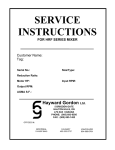
SERVICE
INSTRUCTIONS
FOR GX/DX (FIXED) SERIES MIXER
Customer Name:
Tag:
Serial No.:
Size/Type:
Reduction Ratio:
Motor HP:
Input RPM:
Output RPM:
AGMA S.F.:
Hayward Gordon Ltd.
5 BRIGDEN GATE
HALTON HILLS, ON
L7G 0A3 CANADA
PHONE: (905) 693-8595
FAX: (905) 693-1452
OFFICES IN:
MONTREAL
514-697-6445
CALGARY
403-253-2737
VANCOUVER
604-986-8764
HAYWARD GORDON LTD
PORTABLE FIXED MOUNT
Section:
Page:
Date:
Rev:
PF-1
2
11/01
0
PLEASE READ BEFORE
UNPACKING MIXER
Your mixer has been tested and shaft straightness verified prior to shipment. Careful handling of shaft prior to and during installation will ensure continued service at specified operating conditions.
The following criteria must be adhered to in order to prevent damage to equipment
or serious injury to operating personnel:
1. Always operate agitator in liquid.
2. Always follow the mounting recommendation for baffles if center mounted, or for properly angled and offset mounting in unbaffled vessels.
3. Always turn the agitator off when filling or drawing liquid levels down through the lower
propeller.
4. Always maintain a minimum liquid level of 2 propeller diameters above the lower propeller.
5. Always rotate the shaft to verify straightness prior to operation in liquid.
6. Always check the mixer drawing for any special operating requirements if using a variable speed mixer.
7. Always set the lower propeller at the end of the shaft and the upper propeller (if any)
not closer than 2 propeller diameters above the lower propeller unless noted otherwise
on the mixer drawing.
8. Always fluidize settled solids before starting mixer.
ANY EXCEPTION TO THE ABOVE SHOULD BE AGREED TO IN WRITING BY
HAYWARD GORDON LTD. AND NOTED ON THE MIXER DRAWING.
HAYWARD GORDON LTD
PORTABLE FIXED MOUNT
Section:
Page:
Date:
Rev:
PF-1
3
11/01
0
HAYWARD GORDON PORTABLE FIXED MOUNT MIXERS
MODELS: GX, DX, GS, DS, GM, DM, SGS, & SGM
SERVICE MANUAL
TABLE OF CONTENTS
INTRODUCTION
General Instructions
pg. 03 & 04
Agitator Shaft
Propeller Installation & Location
Operation
Disassembly & Assembly Instruction
Cross-section & Parts list “DX” Mixer
Cross-section & Parts list “GX” Mixer
Mechanical seal
Stuffing Box
Shut-off Device
pg. 05
pg. 06
pg. 07
pg. 08
pg. 09 & 10
pg. 11, 12 & 13
pg. 14, 15, 16 & 17
pg. 18, 19 & 20
pg. 21
INSTALLATION
MOUNTING DIAGRAMS & DIMENSIONS
Mounting Table
“DX” General Dimensions & Weights
“GX” General Dimensions & Weights
pg. 22
pg. 23
pg. 24
HAYWARD GORDON LTD
PORTABLE FIXED MOUNT
Hayward Gordon’s portable mixers are furnished in gear and direct drive designs.
Both types are available in fixed mount and
clamp mount. This manual concerns the
fixed mount designs only.
If additional information is required, contact
your nearest Hayward Gordon representative.
All inquiries must be accompanied by the
following information:
1) Mixer Size and Type (Model)
2) Hayward Gordon Serial Number
NOTE: Orders for renewal parts must include the description and part number
shown on the parts list, in addition to the
above info.
GENERAL INSTRUCTION
1. The Seller’s Warranty applies insofar as
the unit is operated within the rating and
service conditions for which it was specifically sold.
2. The purchaser must prevent the existence of any destructive external conditions, which might typically include vibratory loads due to critical speeds, severe
shock loading, mechanical or thermal
overloads, or other conditions that may
adversely affect operation. The unit
must be installed and maintained in accordance with the instructions provided
in this manual.
3. In the event of malfunction within the
warranty period, Hayward Gordon must
be notified within 30 days if it is intended
that the warranty is to cover the incident.
Section:
Page:
Date:
Rev:
PF-1
4
11/01
0
4. Adequate installation, maintenance and
safety instructions must be given by the
user to personnel directly responsible
for the operation of the mixer drive.
5. Guards, alarms, heaters, and safety devices, which may be furnished by
Hayward Gordon must be installed by
the user.
6. The user is also responsible for the furnishing and installing of any additional
guards or safety equipment needed to
protect operating personnel as required.
7. Any apparent or suspected damage
sustained by equipment manufactured
or furnished by Hayward Gordon during
transport from the factory to the user
should be immediately reported to
Hayward Gordon and the Carrier.
8. Upon delivery of the equipment furnished, careful inventory must be made
against shipping papers to determine
whether any shortages exist in the delivered material. Any such shortages must
immediately be reported to Hayward
Gordon Ltd. and the Carrier if a timely
claim is to be made.
9. The installation of most power transmission equipment does not normally require the services of a factory engineer.
These services are not included in the
selling price of the equipment unless
specifically agreed upon in writing by the
seller and purchaser. In applications requiring a more complex arrangement for
components, consideration should be
given to the user for a factory engineer
HAYWARD GORDON LTD
PORTABLE FIXED MOUNT
for construction, supervision or checkout of the installation. These services
are available from Hayward Gordon Ltd.
10. All electric motors are either totally enclosed or explosion proof, single or
three phase, NEMA Style C footless.
This style of motor is standard with all
motor manufacturers.
11. Inspect unit for corrosion. Notify
Hayward Gordon immediately if corrosion is present.
12. This manual lists a number of safety
precautions. Follow them, and insist that
those working for you do the same. An
accident is usually caused by neglect or
oversight. All unauthorized personnel
must be required to remain a safe distance away from rotating shaft, coupling,
propellers, impellers, etc..
Section:
Page:
Date:
Rev:
PF-1
5
11/01
0
13. Before start-up all Hayward Gordon
Mixer drives should be checked for lubrication.
14. SAFETY INFORMATION
WARNING
In the installation, operation and maintenance of mixer drives, SAFETY comes
first. Use proper clothes, tools, and
methods of handling to prevent serious
accidents. The safety precautions listed
in this manual MUST BE FOLLOWED by
all personnel working on equipment;
otherwise, serious injury may result.T
HAYWARD GORDON LTD
PORTABLE FIXED MOUNT
Section:
Page:
Date:
Rev:
PF-1
6
11/01
0
INSTALLATION INSTRUCTIONS
AGITATOR SHAFT INSTALLATION
To install agitator shaft, remove bolts (5) and inspection cover (7). If drive pin (8) and flex
loc nut (13) are in position, unbolt and remove. Loosen setscrews (10). Coat drilled end of
agitator shaft with commercial rust preventive (i.e. CRC-556 or WD-40) if needed and
check that the shaft is free from burrs and large nicks. Reinstall drive pin and flexloc nut
and tighten to 6 ft.lbs. Tighten setscrews onto flats to 6 ft.lbs. Replace inspection cover.
Section:
Page:
Date:
Rev:
HAYWARD GORDON LTD
PORTABLE FIXED MOUNT
PROPELLER INSTALLATION
Slide single or dual propellers onto shaft
noting which is upper side of each propeller
from the figures below. Tighten setscrews
to 6 ft.lbs. For severe duty, the shaft should
be dimpled for the setscrew. The lower
propeller is normally positioned at the end
of the shaft and the upper propeller, (if provided), at least two propeller diameters below the liquid level. To determine pitch
face, place a straight edge across the blade
width. If the straight edge contacts almost
entire width, this is the pitch face. If the
straight edge touches near the center only,
this is the back face.
Your mixer has been tested and shaft
straightness verified prior to shipment.
Careful handling of shaft prior to and during
installation will ensure continued service at
specified operating conditions.
Always follow mounting recommendation
for baffles if center mounted, or for properly
angled and off-set mounting in un-baffled
vessels.
Always set lower propeller at end of shaft
and upper propeller (if any) not closer than
2 propeller diameters above the lower propeller unless noted otherwise on the mixer
drawing.
PROPELLER LOCATION
The bottom propeller on the agitator shaft
should be positioned no less than 1.5 times
and not more than 3 times the propeller diameter from the bottom of the tank. Where
applicable, the top propeller should be positioned a minimum of 24 inches below surface of the liquid.
PF-1
7
11/01
0
ROTATION
LEADING EDGE
SWEPT BACK
STRAIGHT EDGE
BACK FACE
(TOP)
PITCH FACE
(BOTTOM)
MOUNTING
Fixed mount mixers used in baffled tanks
should be positioned such that the agitator
shaft is centered and vertical in tank. If tank
has no baffles, agitator shaft should be angled and offset.
The mixer may be supported by a wall or
column when tank design does not allow
support for the mixer. Refer to diagram on
page 22.
HAYWARD GORDON LTD
PORTABLE FIXED MOUNT
Section:
Page:
Date:
Rev:
PF-1
8
11/01
0
OPERATION
GENERAL
When starting up the portable mixer for the
first time, proceed cautiously. Even when
the best installations and practices are followed, errors or omissions are always possible.
PRELIMINARY CHECKS:
It is recommended that the following checks
be made before the portable mixer is
started:
a. Check all mounting bolts and/or clamps
for proper installation.
b. Check covers for proper installation.
c. Check all electrical connections.
d. Check for grease leaks.
INITIAL START-UP
The portable mixer has been spin tested at
the factory, however, during the initial startup, the following precautions must be observed:
a. Check for grease leaks.
b. Check for any unusual noise or overheating. If this occurs, mixer must be stopped
immediately and the problem corrected.
MAINTENANCE
During operation, the mixer should be observed for evidence of overheating (temp.
>1800F), grease leaks and/or unusual
noise. If any of these problems develop
shut down the mixer and determine the correct cause.
Note that it is normal for the lower bearing
in the direct drive model mixers (e.g. DX), to
operate at a temperature 25 oC (40 oF) or
more above the ambient temperature.
LUBRICATION
The gear drive model mixers (e.g. GX models) have the gear cavity fully packed with
grease (Esso Unirex EP-1) at the factory
and unless grease has been removed, or
otherwise depleted the mixer does not require the addition of grease during its lifetime. If grease addition is done, the gear
cavity must be filled to 85-90% of its full capacity, eliminating all air pockets and completely submerging the gears. In addition,
gear drive models are supplied with permanently lubricated bearings and therefore do
not require additional lubrication.
Hayward Gordon direct drive mixers (e.g.
DX models) have permanently lubricated
bearings and therefore require no additional
lubricant.
If units have been supplied with either packing or mechanical shaft sealing devices (e.
g. models DM, DS, GM or GS) refer to the
appropriate section in this manual for
proper lubrication of these items.
DISASSEMBLY INSTRUCTION
Referring to the parts list, begin as follows:
a. Disconnect power supply. Remove
agitator shaft, (see installation sec
tion). Remove mixer from tank or
support.
b. Remove bolts (16) and separate top
cover (17), motor assembly from mixer
housing.
c. Pinion is locked on motor shaft with
"Loctite 601" adhesive. Pinion must be
pressed of shaft. Heating pinion will
weaken adhesive bond. Apply heat only
HAYWARD GORDON LTD
PORTABLE FIXED MOUNT
until adhesive bond is weakened enough to
ease pinion removal. Pinion temperature
must not exceed 500 F. Note position and
orientation of pinion to aid re-assembly.
d. Remove grease from housing. Align
holes in gear (2) with socket head cap
screws (3). Insert wrench through holes
and remove screws.
e. Pull hollow shaft (21) assembly out of
housing. When lower bearing (11) con
tacts upper bearing mount in housing,
guide bearing through mount.
f. Gear is locked on hollow shaft with
"Loctite 601". See (c) for removal in
structions.
g. Press bearing off shaft. Bearing can be
heated to a maximum of 200° F to ease
removal and re-assembly.
Section:
Page:
Date:
Rev:
PF-1
9
11/01
0
ASSEMBLY INSTRUCTION
Assembly reverses disassembly. Adhere to
the following guidelines:
a. Clean and inspect all parts.;
b. Apply grease to inside lip of lower oil
seal (12).
c. Replace gasket (27) between top cover
(17), through cap (4), and housing (1).
d. Follow manufacture's instructions when
reinstalling pinion and gear with "loctite
601" or equivalent. Vapor phase clean
ing or washing of gear members in a
chlorinated solvent, before application of
adhesive, is recommended.
e. Refill gear cavity of housing with Esso
Unirex EP-1 or equivalent to 85-90% of
its full capacity, eliminating all air pock
ets.
HAYWARD GORDON LTD
PORTABLE FIXED MOUNT
PARTS LIST, DIRECT DRIVE MODEL DX
Section:
Page:
Date:
Rev:
PF-1
10
11/01
0
HAYWARD GORDON LTD
PORTABLE FIXED MOUNT
Section:
Page:
Date:
Rev:
PF-1
11
11/01
0
PARTS LIST, DIRECT DRIVE MODEL DX
ITEM NO.
PART NUMBER
1
2075550001
5
70303007
7
4070850001
8
DESCRIPTION
QTY. UNIT
HOUSING
1
SELF TAPPING SCREW
4
INSPECTION COVER
1
72783009
HEX HEAD BOLT
4
9
52549500
GASKET
1
10
73275011
SET SCREW ( 1.25" SHAFT )
2
10
73275012
SET SCREW ( 0.75" SHAFT )
2
*11
50149500
BEARING, BALL
1
*12
50349500
OIL SEAL
1
13
73875017
FLEXLOC NUT
1
18
72783037
HEX HEAD SCREW C/W
4
74682033
LOCKWASHER
4
21
4030350101
SLEEVE ( 1.25" SHAFT )
1
21
4030350001
SLEEVE ( 0.75" SHAFT )
1
22
2185550101
ALUMINUM SPACER
1
23
50403500
RETAINING RING
1
24
4030350401
SLEEVE ADAPTOR FOR MOTOR SHAFT
1
25
73284010
FULL DOG SET SCREW
1
26
73275011
SET SCREW SOC,HEAD,CAP ( 1.25" SHAFT )
1
26
73275012
SET SCREW SOC,HEAD,CAP ( 0.75" SHAFT )
1
39
MOTOR
1
70
SHAFT
1
71
SET SCREW
1
72
PROPELLER
1
*RECOMMENDED SPARE PARTS
REFER TO PAGE 9 FOR DRAWING.
HAYWARD GORDON LTD
PORTABLE FIXED MOUNT
Section:
Page:
Date:
Rev:
PARTS LIST, GEAR DRIVE MODEL GX (0.75” & 1.25” SHAFT)
PF-1
12
11/01
0
HAYWARD GORDON LTD
PORTABLE FIXED MOUNT
Section:
Page:
Date:
Rev:
PARTS LIST, GEAR DRIVE MODEL GX (1.50” SHAFT)
PF-1
13
11/01
0
HAYWARD GORDON LTD
PORTABLE FIXED MOUNT
Section:
Page:
Date:
Rev:
PF-1
14
11/01
0
PARTS LIST, GEAR DRIVE
ITEM NO.
1
*2
3
4
5
*6
7
8
9
10
10
*11
*12
13
14
*15
16
17
18
19
*20
21
21
28
29
39
70
71
72
PART NUMBER
2075550301
53049500
73084002
2105550001
70303007
50149500
4070850001
72783009
52549500
73275011
73275012
50149500
50349500
73875017
77049500
50349501
72783003
4275550001
72783034
4030350501
53049501
4030350301
4030350201
4130350001
73084033
4081060301
52549501
52549502
52549503
75210500
75303503
DESCRIPTION
HOUSING
GEAR
SCREW,SOC.HEAD,CAP
THRU CAP
SELF TAPPING SCREW
BEARING, BALL
INSPECTION COVER
HEX HEAD BOLT
GASKET
SET SCREW ( 1.25" DIA.SHAFT )
SET SCREW ( 0.75"DIA.SHAFT )
BEARING, BALL
OIL SEAL
FLEXLOC NUT
EXPANSION PLUG
OIL SEAL
HEX HEAD SCREW
TOP COVER
HEX HEAD SCREW
SLEEVE SEAL
PINION
SLEEVE ( 1.25" DIA.SHAFT )
SLEEVE ( 0.75"DIA.SHAFT )
THRUST PLATE (1.5” DIA SHAFT)
SCREW SOC. HD. CAP (1.5” SHAFT)
MOTOR
SHAFT
SET SCREW
PROPELLER
GEAR KEY
GASKET ( TOP COVER )
GASKET ( BEARING CAP )
GASKET ( MOTOR )
DOWEL PINS ( MOTOR PLATE )
DRIVE PINS ( H.S. PINION )
QTY.
1
1
3
1
4
1
1
1
1
2
2
1
1
1
1
1
6
1
4
1
1
1
1
1
1
1
1
1
1
1
1
1
1
1
1
HAYWARD GORDON LTD
PORTABLE FIXED MOUNT
DOUBLE MECHANICAL SEALS
To avoid damaging a double mechanical
seal, the seal chamber should always be
pressurized before the mixing vessel. Double mechanical seals require that a suitable sealant fluid be introduced to the seal
chamber at a pressure approximately 10%
above the vessel pressure. The pressure
within the seal chamber cannot exceed 20
psi. above the vessel pressure nor can it
exceed the maximum pressure rating of
the seal itself. Never operate the mixer until the sealant has been introduced to the
seal.
For optimum seal life, the best choice for a
sealant is light mineral oil. However, when
oil cannot be used because of the possibility of process contamination one of the
process fluids or another fluid (with the
proper viscosity and lubricity) may be
used. The sealant fluid must not rust or
attack the seal components or seal housing. The sealant temperature must be
maintained below the vaporization or boiling point and above the freezing point of
the sealant. The sealant temperature
must be controlled to assure optimum lubricity. The sealant temperature must also
be adjusted, by means of the sealant pressurizing system, to meet the operating
conditions assuring sufficient heat removal
thereby retaining seal internal components
at a safe operating temperature.
If leakage occurs at the mechanical seal,
inspect the seal area to be sure that deposits of foreign or process material have
not accumulated. Solids build-up in close
tolerance areas and can score the shaft, or
damage sealing faces, thus causing leakage. Remove and clean mechanical seal
Section:
Page:
Date:
Rev:
PF-1
15
11/01
0
thoroughly and area of shaft where material has build up.
Note: Use clean lubricant and keep system
clean in order to achieve maximum seal
life. If a dead-end lubrication system is
used, the seal chamber and lubrication
system should be flushed every 2500
hours or every 6 months, whichever occurs
first.
MECHANICAL SEAL REMOVAL INSTRUCTION
1.
2.
3.
4.
5.
6.
Depressurize mixing tank and disconnect all lubricating lines, electrical connections, and control devices.
Remove plug (Item 12 on pg. 17)
From mechanical seal housing and
loosen set screws
Support the agitator shaft either from
within the mixing tank or with a clamp
fastened around the shaft directly
above the mechanical seal housing. If
a clamp is used, another means of
supporting the shaft must also be
available, as the clamp must be removed to enable removal of the mechanical seal.
Remove mixer drive inspection cover
(Item 7 on pg.05 or 11, depending on
type of drive ) and loosen set screws
(Item 10) above and below the drive
pin (Item 8). Remove drive pin.
Remove mixer drive mounting bolts
from mechanical seal flange and lift
the mixer drive from the flange to expose the mechanical seal assembly
and the agitator shaft.
If a clamp was used to support the
agitator shaft while the mixer drive
was removed, another method of sup-
HAYWARD GORDON LTD
PORTABLE FIXED MOUNT
7.
porting the shaft must now be provided
to enable removing and servicing the
mechanical seal.
While maintaining support to the agitator shaft, unbolt the mechanical seal
housing from the mounting flange and
slide the mechanical seal off the agitator shaft and service as necessary
Reinstallation Procedure
The reinstallation of the mechanical seal is
essentially the reverse of the removal procedure. Be sure that internal mechanical
seal elements are positioned evenly between the stationary faces and that all necessary mechanical connections have been
made before the seal set screws are tightened.
Section:
Page:
Date:
Rev:
PF-1
16
11/01
0
Section:
Page:
Date:
Rev:
HAYWARD GORDON LTD
PORTABLE FIXED MOUNT
SINGLE MECHANICAL SEAL
DURAMETALLIC VRA
PART NO.
DESCRIPTION
QTY / UNIT
*1
GLAND
1
*2
ROTATING FACE
1
*3
‘O’ RINGS
2
*4
HEX HEAD BOLT (4)
2
PF-1
17
11/01
0
Section:
Page:
Date:
Rev:
HAYWARD GORDON LTD
PORTABLE FIXED MOUNT
SINGLE MECHANICAL SEAL
John Crane Type 32
Part Number Description
Qty/unit
1
Seal Seat
1
3
Rotating Member
1
4
O-ring
1
5
Retainer
1
8
T-Bar
4
11
O-ring
1
12
Gasket
2
13
Gland Plate
1
PF-1
18
11/01
0
HAYWARD GORDON LTD
PORTABLE FIXED MOUNT
Section:
Page:
Date:
Rev:
DOUBLE MECHANICAL SEAL
*1
PART NO.
DESCRIPTION
UPPER STATIONARY FACE
QTY / UNIT
1
*2
*3
*4
*5
LOWER STATIONARY FACE
ROTATING ASSEMBLY
“O” RING (ROTATING FACE)
“O” RING (STATIONARY FACE)
1
2
2
1
*6
*7
*8
9
GASKET (STATIONARY FACE 1/16" THK.)
GASKET (STATIONARY FACE 1/16" THK.)
LIP SEAL
SEAL HOUSING
1
1
1
1
10
11
12
13
GREASE FITTING
FLUSH OUTLET 1/4 “ N.P.T.
STRIGHT THREADED PLUG
HEX HEAD BOLT C/W LOCKWASHER
1
1
1
4
14
FLUSH INLET 1/4 “ N.P.T.
1
PF-1
19
11/01
0
HAYWARD GORDON LTD
PORTABLE FIXED MOUNT
Section:
Page:
Date:
Rev:
PF-1
20
11/01
0
STUFFING BOX INSTRUCTIONS
The purpose of the stuffing box packing is
NOT TO STOP leakage, but to limit it to a
practical amount. If the gland is tightened to
prevent leakage, packing life will be shortened and shaft damage may occur.
Lubrication
For best stuffing box performance, lubricant
should be introduced CONTINUOUSLY at
pressures between 5 to 15 PSI above tank
pressure.
If intermittent lubrication is provided by
means of a grease gun, care must be taken
to prevent over lubrication. An amount of
grease that fills the lubricant cavity and is
distributed evenly throughout the packing
area is sufficient for proper lubrication. The
stuffing box is shipped WITHOUT lubricant,
because of the danger of using a lubricant
that may contaminate the product.
Before using, please check that packing
and lubricant are of physically and chemically suitable for the service conditions.
START UP INSTRUCTIONS STUFFING
BOX
1. Tighten the gland nuts to “finger tightness”
2. Start the mixer and run it until the stuffing box has reached a constant operating temperature. When tightening the
gland nuts, be careful to avoid cocking
the gland. Even tightening of the gland
will seat the packing while it is warm and
plastic.
3. Again, loosen the gland nuts to finger
tightness and restart mixer. Leakage
may be excessive, but do not take up on
the gland nuts for the first 20 to 30 minutes,
4. If, after this initial run-in period, the leakage is still excessive, adjust by tightening the gland nuts evenly - one flat or a
sixth of a turn at a time. This should be
done every 30 minutes until leakage is
reduced to a normal level.
5. Adjustments must always be done
gradually, over several hours, and held
HAYWARD GORDON LTD
PORTABLE FIXED MOUNT
Section:
Page:
Date:
Rev:
PF-1
21
11/01
0
RE-PACKING PROCEDURE
1. Remove the split gland, all packing, and
lantern ring. Carefully avoid scoring the
shaft with the packing hook or removal
tool.
2. Inspect the shaft and lantern ring. Lantern ring, lubrication channel, and holes
must be free of dirt. Minor shaft wear
should be worked smooth. Where excessive wear exists, the shaft should be
built up and re-machined to give a
smooth finish, or replaced. Clean stuffing box thoroughly, checking to ensure
the lubrication holes are free and clear.
3. The location of the lantern ring should
be pre-determined for proper alignment
between lubrication holes and grease
lines or fittings.
4. Insert first ring of packing into the stuffing box. Install a split spacer (preferably
of wood ) into the box against the packing ring. Install gland and tighten evenly
against the spacer, so that packing ring
is firmly seated and spread to effect a
good seal against the inside walls of the
box as well as the shaft. When tightening the gland, pull it up evenly so each
ring will be packed squarely into the box,
assuring a good seal. Repeat this procedure for each ring. The individual packing joints must be staggered at 90 degrees.
5. After the box has been completely
packed, replace the split gland, tightening the gland nuts to finger tightness.
STANDARD PACKING SPECIFICATIONS
PACKING TYPE
SERVICE
STYLE C1050
Conc.Acid
Soft braided packing. Contains Teflon dispersion
on the yarns with heat resistant lubricant. Clear
and colorous
STYLE K1730
Sewage, mild chemicals, mild
Braided from a special kevlar aramid fiber with caustic and abrasive type
special lubricant. A high tensile strength packing. service
Temp.
pH
500 °F
Max
0-14
500 °F
Max
3-10
HAYWARD GORDON LTD
PORTABLE FIXED MOUNT
STUFFING BOX, HIGH PRESSURE (0-150 PSI)
PART NO.
DESCRIPTION
1
STUFFING BOX FLANGE ASSEMBLY * +
2
GLAND PLATE *
3
PACKING GLAND *
4
STUD
5
NUT
6
PACKING RINGS *
7
LANTERN RING *
8
RELIEVE PLUG
9
GREASE FITTING
-For Material type refer to unit assembly drawing.
-Mounting flange is ANSI raised face on alloy units only.
Steel units are ANSI flat face.
Section:
Page:
Date:
Rev:
PF-1
22
11/01
0
HAYWARD GORDON LTD
PORTABLE FIXED MOUNT
Section:
Page:
Date:
Rev:
INSTRUCTIONS FOR OPERATING TANK SHUT-OFF DEVICE
TO ENGAGE THE SHUT OFF DEVICE
(REPACK FEATURE):
1. Remove 4 screws (17).
2. Tighten 4 jacking screws (11) evenly until
repack collar (3) is engaged approximately 1
3/16" gap between jacking plate (10) and
mounting flange (2).
3. Disconnect shaft from gearbox (refer to
Mixer Shaft Installation in Maintenance Instructions).
4. Remove 4 screws (15).
5. Remove gearbox from shaft.
6. Remove thrust collar (21) , seal gland (9),
mechanical seal head (7).
7. Reinstall thrust collar (21) on shaft, seating it on flange. Lock it to shaft at this position.
REVERSE THE ABOVE INSTRUCTIONS
TO RESTORE THE UNIT TO AN OPERITEM
1
2
3
4
5
6
7
8
9
10
11
12
13
14
15
16
17
18
19
20
21
22
23
DESCRIPTION
DRIVE ASSEMBLY
MOUNTING FLANGE
REPACK COLLAR
‘O’ RING
SET SCREW
‘O’ RING
ROTATING FACE
STATIONARY FACE
GLAND
JACKING PLATE
JACKING SCREW
STUDS
HEX NUT
LOCK WASHER
HEX HEAD SCREW
LOCK WASHER
HEX HEAD SCREW
LOCK WASHER
SHAFT
PROPELLER
THRUST COLLAR
SCREW, SOC. HEAD, CAP
LOCKWASHER
QTY
1
1
1
1
1
2
1
1
1
1
4
4
4
4
4
4
4
4
1
1
2
2
PF-1
23
11/01
0
HAYWARD GORDON LTD
PORTABLE FIXED MOUNT
Section:
Page:
Date:
Rev:
FIXED MOUNT CONFIGURATION FOR UN-BAFFLED TANKS
24
27
30
33
36
39
42
45
48
51
54
57
60
63
66
69
72
75
78
81
84
87
90
93
96
99
102
105
108
111
114
117
120
126
132
138
144
150
156
162
168
0.25 HP TO 0.75 HP
C
B
6
3-1/2
7-1/4
4-1/4
8-3/8
4-7/8
9-1/2
5-1/2
10-1/2
6-1/8
10-7/8
6-7/8
13
7-1/2
14
8-1/8
15-1/8
8-3/4
16-3/8
9-1/2
17-1/2
10-1/8
18-1/2
10-3/4
19-5/8
11-3/8
21
12-1/8
22
12-3/4
23-1/8
13-3/8
24-1/2
14-1/8
25-1/2
14-3/4
26-1/2
15-3/8
27-3/4
16
28-3/4
16-5/8
30
17-3/8
31-1/8
18
32
18-1/2
33-1/2
19-3/8
34-5/8
20
35-1/4
20-3/8
36-3/4
21-1/4
37-7/8
21-7/8
38-3/4
22-3/8
40-1/4
23-1/4
41-3/8
23-7/8
42-1/2
24-1/2
44-3/4
25-7/8
47
27-1/8
49-3/8
28-1/2
51-1/2
29-3/4
53-7/8
31-1/8
56
32-3/8
58-1/4
33-5/8
60-7/8
35-1/8
1.0 HP TO 3.0 HP
C
B
4-7/8
2-7/8
6-1/4
3-5/8
7-3/8
4-1/4
8-1/2
4-7/8
9-3/4
5-5/8
10-7/8
6-1/4
11-7/8
6-7/8
13-1/4
7-5/8
14-1/8
8-1/8
15-3/8
8-7/8
16-1/2
9-1/2
17-1/2
10-1/8
18-7/8
10-7/8
20
11-1/2
21
12-1/8
22-1/8
12-3/4
23-3/8
13-1/2
24-1/2
14-1/8
25-1/2
14-3/4
26-5/8
15-3/8
27-7/8
16-1/8
29
16-3/4
30-1/8
17-3/8
31-1/4
18-1/8
32-1/2
18-3/4
33-1/2
19-3/8
34-5/8
20
35-3/4
20-3/4
36-7/8
21-3/8
38-1/8
22
39-1/4
22-5/8
40-3/8
23-3/8
42-1/8
24
43-7/8
25-3/8
46-1/8
26-5/8
48-3/8
28
50-7/8
29-1/4
53
30-5/8
55-1/4
32
57-1/2
33-1/4
59-7/8
34-5/8
PF-1
24
11/01
0
Section:
Page:
Date:
Rev:
HAYWARD GORDON LTD
PORTABLE FIXED MOUNT
DIRECT DRIVE GENERAL DIMENSIONS & WEIGHTS
Model
DX-14
DX-13
DX-12
DX-34
DX-11
DX-15
DX-2
DX-3
HP
0.25
0.33
0.5
0.75
1.0
1.5
2.0
3.0
A
21.1
21.1
21.1
23.4
23.4
23.4
26.0
27.6
Approx. Wt.
92
95
100
125
130
136
142
155
PF-1
25
11/01
0
Section:
Page:
Date:
Rev:
HAYWARD GORDON LTD
PORTABLE FIXED MOUNT
GEAR DRIVE GENERAL DIMENSIONS & WEIGHTS
Model
GX-14
GX-13
GX-12
GX-34
GX-11
GX-15
GX-2
GX-3
HP
0.25
0.33
0.5
0.75
1.0
1.5
2.0
3.0
A
22.9
22.9
22.9
25.1
25.1
25.1
27.8
29.3
Approx. Wt.
125
128
130
132
132
142
154
170
PF-1
26
11/01
0