1
Jacek F. GIERAS1
University of Technology and Life Sciences, Bydgoszcz
Electric Power System of Tu-154M Passenger Aircraft
Abstract. The paper discusses the electric power system of the Tu-154M aircraft. After brief introduction to aircraft power systems, the results
of reverse design and analysis of the GT40PCh6 wound-field synchronous generator including short circuit have been presented. Electric power
distribution and assignment of electric grids (channels) to respective aircraft energy consumers has been discussed. Most important electric loads,
i.e., the fuel system with electric motor driven pumps, wing anti-ice electric system and exterior and interior lighting equipment have been described.
An example of failure of GT40PCh6 synchronous generator is the fire of the Tu-154B-2 on January 1, 2011 before taking off at Surgut airport (flight
7K348).
Streszczenie. Artykul omawia system elektroenergetyczny samolotu Tu154M. Po krotkim wprowadzeniu do systemow elektroenergetycznych samolotow, przedstawiono wyniki projektowania odwrotnego oraz analizy generatora synchronicznego GT40PCh6 o wzbudzeniu elektromagnetycznym z
uzwglednienium przebiegow pradow podczas zwarcia. Opisano dystrybucje energii elektrycznej oraz przyporzadkowanie odbiornikow energii elektrycznej samolotu do poszczegolnych sieci (kanalow). Scharakteryzowano najwazniejsze obciazenia elektryczne, tzn. system paliwowy z pompami
napedzanymi silnikami elektrycznymi, system elektryczny zapobiegajacy osadzaniu sie lodu na frontowych powierzchniach skrzydel oraz oswietlenie
zewnetrzne i wewnetrzne. Przykladem awarii generatora synchronicznego GT40PCh6 jest pozar Tu-154B-2 w dniu 1 stycznia 2011 przed startem na
lotnisku w Surgucie (lot 7K348).
(System elektroenergetyczny samolotu pasazerskiego Tu-154M)
Keywords: aircraft electric power system, distribution system, electric loads, electric motor-driven fuel pumps, fuel system, lighting, synchronous
generator, Tu154M, wing anti-ice electric system
Słowa kluczowe: generator synchroniczny, odbiorniki energii, oswietlenie elektryczne, pompy paliwa napedzane silnikami elektrycznymi, system
dystrybucji energii elektrycznej, system elektroenergetyczny samolotow, system odmrazania elektrycznego skrzydel, system paliwowy, Tu-154M
Introduction to aircraft electric systems
The function of the aircraft electrical system is to generate, regulate and distribute electrical power throughout the
aircraft [4, 7]. Aircraft electrical components operate on
many different voltages both AC and DC. Most systems use
115/200 V AC (400 Hz) and 28 V DC. There are several different electric generators on large aircraft (Fig. 1) to be able to
handle loads, for redundancy, and for emergency situations,
which include [4, 7, 8]:
1. engine driven main generators;
2. auxiliary power unit (APU);
3. ram air turbine (RAT);
4. external power, i.e., ground power unit (GPU).
Each of the engines on an aircraft drives one or more
a.c. generators (Fig. 2) via special transmission system.
consisting of two synchronous machines, i.e., wound-field
synchronous exciter and permanent magnet (PM) subexciter.
The power circuit is shown in Fig. 2. PM brushless generators are rather avoided due to difficulties with shutting down
the power in failure modes. There are also attempts of using switched reluctance (SR) generators with no windings or
PMs on the rotor. A generator control unit (GCU), or voltage
regulator, is used to control generator output. The generator
shaft is driven by a turbine engine with the aid of gears or
directly by low spool engine shaft.
Fig. 1. Aircraft generators: 1 – main generator, 2 – APU, 3 – RAT, 4
– GPU [4].
Fig. 2. Architecture of main wound-field synchronous generator [4].
The electricity produced by these generators is used in
normal flight to supply the entire aircraft with power. The
power generated by APUs is used while the aircraft is on
the ground during maintenance and for engine starting. Most
aircraft can use the APU while in flight as a backup power
source. RATs are used in the case of a generator or APU
failure, as an emergency power source. External power may
only be used with the aircraft on the ground. A GPU (portable
or stationary unit) provides AC power through an external
plug. Aircraft generators are typically three-phase, salientpole, wound-field synchronous generators with outer stator
with distributed-parameter winding and inner rotor with concentrated coil winding [4]. The field excitation current is provided to the rotor with the aid of a brushless exciter system
Typical AC power system of aircraft is 115/200 V, 400
Hz, three-phase system. Since the speed of an aircraft engine varies from full power speed to flight idle speed (typically
2:1), and frequency is proportional to the generator rotational
speed, a device for converting a variable speed to constant
speed is necessary [7]. The so called constant speed drive
(CSD), i.e., a complex hydromechanical device was common
until the late 1980s. Nowadays, solid state converters have
replaced unreliable CSDs with variable speed/constant frequency (VSCF) systems.
Typical aircraft have from 16 to 160 km of wire installed
such that wire from one system is often collocated with wire
from many other systems. Electrical wiring can be classified
into power wiring (heavy current) and light current wiring. In
PRZEGLAD
˛ ELEKTROTECHNICZNY, ISSN 0033-2097, R. 89 NR 2a/2013
300
Table 1. AC power systems of Tu-154M aircraft
Voltage, V
115/220
36
Number of phases
3
3
Nominal power of the system
120 kVA 6.0 kW
Number of channels
3
2
Nominal power per channel
40 kVA
3.0 kW
Maximum power per channel
50 kVA 3.75 kW
5-min overload power
60 kVA 4.50 kW
5-s overload power
80 kVA
6.0 kW
Frequency, Hz
400
400
Nominal current per channel, A
111
46.8
Maximum current per channel
138
58.0
Power factor
0.8 to 1.0
0.8
modern aircraft, power wires, feeding e.g., electric motors,
are not routed through the cockpit. Switches in the cockpit
are connected to light current wires (control wires), which activate relays of heavy current circuit.
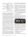
Fig. 3. Main power distribution systems 115/220 V AC and 36 V
AC of Tu-154M. 1 – rectifiers VU-6A (backup and No 1), 2 – rectifier
VU-6A No 2, 3 – right junction box (JB) 115/200 V, 4 – converter
PTS-250 No 2, 5 – converter PTS-250 No 1, 6 – JB of kitchenette, 7
– JB of anti-ice system, 8 – right panel of generators, 9 – generator
GT40PCh6 No 3, 10 – JB of APU 200 V, 11 – generator GT40PCh6
of APU, 12 – generator GT40PCh6 No 2, 13 – generator GT40PCh6
No 1, 14 – external power connector for ShRAP-400-3F GPU, 15 –
left panel of generators, 16 – left JB 115/220 V, 17 – transformer No
2, 18 – transformer No 1, 19 – right JB 36 V AC, 20 – left JB 36 V
AC, 22 - flight attendant’s switchboard, 23 – converter POS-125Ch
[3, 13].
Electric power supply system of Tu-154M
The main power supply system of the Tu154M is a threephase 115/200V, 3 × 40 kVA, 400 Hz, AC system [3, 10, 13].
The three-phase 115/200 V AC power is delivered by three
GT40PCh6 wound-field synchronous generators. The fourth
GT40PCh6 AC generator is the APU generator. The APU is
also equipped with 27 V DC GS-12TO starter-generator.
The secondary three-phase, 36 V, 400 Hz, 46.8-A, 2 × 3
kW AC system takes power from the main system via two
three-phase 206/37 V, Dy, TS330S04B transformers. The primary windings of TS330S04B transformers are fed from the
navigation piloting system (NPK) bus bars. The 115/200 V
AC and 36 V AC power systems are shown in Fig. 3 and described in Table 1. The third power system is the 27 V, 200 A,
DC, single-circuit system (Fig. 4), which receives power from
the main system via transformer and three VU-6A rectifiers
and four 20NKVN-25 batteries.
The emergency 36 V AC power system (instead of RAT)
consists of two 20-30/36 V, 400 Hz, 250 VA PTS-250 transistor inverters fed from batteries. It feeds among others the
gyro horizon AGR-144. Another single-phase 115-V emergency system takes electric power from batteries via POS125TCh solid state converter.
The simplified electrical diagram of 115/200 V AC power
generation system with three main generators and APU generator is shown in Fig. 5. The block diagram of overall electric
system of the Tu-154M is shown in Fig. 6.
301
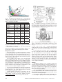
Fig. 4. Power distribution system 27 V DC of Tu-154M. 1 – Rectifier
VU-6A No 2, 2 – right panel of protection control, 3 – Rectifier VU6A No 1, 4 – Left panel of protection control, 5 – junction box (JB)
of kitchen, 6 - left power JB 27 V DC, 7 – electrical panel of flight
attendant, 8 – rear JB (in left panel of generators), 9 – JB of APU
and batteries, 10 – batteries 20NKBN-25, 12 – JB of batteries, 12 –
JB of VU-6A backup rectifier, 14 – backup rectifier VU-6A, 15 – “PT”
JB, 16 – electrical panel of household devices, 17 – electrical panel
of crew cupboard, 18 – flight attendant’s switchboard [13].
Fig. 5. Simplified schematic of main electric power generation system 115/220 V AC when all generators G1, G2, and G3 are in parallel. 1 – contactor TKS133DOD “reconnection of grid No 1 on generator No 3”, 2 – contactor TKS233DOD “switching generator No 1
on grid”, 5 – contactor TKS233DOD “switching APU on grid No 2”,
17 – contactor TKS233DOD “switching generator No 2 on grid”, 20 –
contactor TKS233DOD “reconnection of grid No 3 on generator No
1”, 21 – contactor TKS233DOD “switching generator No 3 on grid”,
27 – contactor TKS233DOD “switching APU or GPU on grid No 3”,
38 – contactor TKS233DOD “switching APU on grid” [2].
Electric power distribution
The main three-phase, 115/200 V, 400 Hz power supply
system is a three-channel system (Figs 3, 5 and 6). One
GT40PCh6 generator feeds one channel (electric grid).
The generator No 1 mounted on the left turbofan engine
No 1 feeds the grid No 1, which in turn feeds the left autonomous bus bars, left bus bar of navigation piloting system (NPK), radio navigation equipment, anticollision flashing
lights SMI-2KM, control systems of slats and stabilizers (motors No 1), fuel pumps No 1,3,5,8,10, rectifiers VU-6B No 1
(No 3), passenger cabins lighting, heaters of windshields of
cockpit, hydraulic pumping station NS-46 of the second hydraulic system, and other loads. The total power consumption of the grid No 1 is 23.2 kVA, 70 A (excluding NS-46).
The generator No 2 of the grid No 2 mounted on the
center engine No 2 feeds anti-ice electric heating elements
of leading edges of wings (slats). The power consumption is
43.6 kVA, 130 A.
The third grid No 3 powered by the generator No 3 installed on the right engine No 3 is loaded with the right autonomous bus bars, right bus bar of navigation piloting system (NPK), control system of slats and stabilizers (motors
PRZEGLAD
˛ ELEKTROTECHNICZNY , ISSN 0033-2097, R. 89 NR 2a/2013
Fig. 6. Block diagram of electric power system of Tu-154M [16].
No 2), fuel pumps No 2,4,6,7,9,11, fuel control system, rectifiers VU-6B No 2 (No 3), air conditioning system, hydraulic
pumping station NS-46 of the third hydraulic system, household equipment and other equipment. The total power consumption is 12 kVA, 45 A (without household equipment and
NS-46). The household equipment needs 13 kVA, 60 A.
In the case of failure of one of the generators, its grid is
automatically reconnected to the operating generators.
The GPU supplies all three electric grids. After starting
any turbofan engine and after switching on any GT40PCh6
generator, the first and the third grid is automatically connected to this generator while the GPU feeds only the second grid. If two generators are on, the GPU is automatically
disconnected from the aircraft electric power system.
Control and protection devices of the main power system are located on the power panel of the flight engineer.
The three-phase 36-V, 400-Hz, two-channel electric power
system feeds the Kurs-MP-2 landing navigation and control
unit, ARK-15M radio compass, Groza-154 radar, Doppler effect velocity and drift angle measure system DISS-3P, and
hydraulic pressure gauge MET-4B. The 36 V AC system also
supplies the gyro horizon (attitude indicator), but its power is
supplied independently of the PTS-250 converter, which receives electrical energy from batteries. The PTS-250 No 1
converter is used as an emergency 36 V AC power source
(Fig. 6). Connection of the converter to the network is made
automatically.
The on-board 27 V DC power system consists of three
VU-6A rectifiers, GS-12TO starter-generator mounted on the
APU, and two four 20NKBN-25 batteries (Fig. 4). The VU6A rectifiers are the basic DC power sources. They get the
power from the first and third grid (from the main 115/200 V
AC system). There are two basic rectifiers and the third rectifier is for redundancy (Fig. 6). The third rectifier is switched
on automatically in the case of failure of one of the basic rectifiers and operates in parallel with the remaining rectifiers.
There is also provision for “forced” connection of the third reserve rectifier.
The 27 V DC GS-12TO APU-mounted starter-generator
delivers power to the DC grid after starting the APU on the
ground until turbofan engines are started and GT40PCh6
synchronous generators operate. In the case of failure of the
main 115/200 V power system in the air, rechargeable batteries are used to supply the most important loads and to start
the APU on the ground in the absence of GPU. Under normal
operation, batteries are connected in parallel to smooth the
DC bus voltage ripple. Rechargeable batteries are installed
in the rear fuselage under the floor of the technical compartment. They can be accessed through a removable hatch in
the floor.
In addition, there is a 27 V AC power supply designed for
household appliances: electric kettles and electric warmer in
the kitchenette-buffet. The system gets its power from the
main system through a TS-330S04A transformer connected
to the grid No 3 via a switch mounted on the flight attendant
switchboard (Figs 3 and 4). The transformer is installed on
the right board, near the frame No 35, in junction box (JB) of
the kitchenette (Fig. 3).
The single-phase 115 V AC, 400 Hz power supply provides electric power to Landish-20 FM radio station, radio
system RSBN-2SA of near-range navigation, Kurs-MP-2 navigation and control unit, and other radio equipment, as well
2IA-7A temperature meters of engine exhaust gases [3]. In
the case of emergency, the electrical power to these loads
comes from the converter MA-100M, which is supplied from
batteries. The connection of converter is made automatically.
The cross section of basic distribution wires is:
• 1.93 to 35.0 mm2 for AC systems;
• 1.5 to 70.0 mm2 for DC systems.
Synchronous generators
The main generators are three 40-kVA, 115/200 V, 400 Hz,
CSD GT40PCh6 wound-field synchronous generators driven
by three D-30KU low-bypass turbofan engines (Fig. 7). Each
generator feeds one channel (grid). There is also a reserve
40-kVA, 115/200 V, 400 Hz power source, the so called APU
which consists of GT40PCh6 synchronous generator driven
by independent TA-6A turbine engine (Fig. 8).
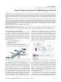
Fig. 7. Turbofan engine D-30KU. 1 – inlet guide vanes heating collector (VNA), 2 – centrifugal air separator of oil system, 3 – fuel-oil heat
exchanger, 4 – main oil pump, 5 – front (main) accessory drive gearbox, 6 – hydraulic pump for thrust reverse, 7 – fuel pump, 8 – sensor
of referred revolutions, 9 - place for aircraft hydraulic pumps NP-25
and NP-89, 10 – fuel pump regulator, 11 – temperature sensor, 12 –
centrifugal regulator of low pressure (LP) rotor, 13 – rotational speed
sensor for the LP rotor, 14 – synchronous generator GT40PCh6, 15
– rear accessory drive gearbox, 16 – constant speed drive (CSD),
17 – mechanism of frequency correction, 18 – air turbine of CSD, 19
– air turbo starter, 20 – overlapping cover of turbo starter, 21 – oil
removal pump. http://ru.wikipedia.org/
The longitudinal section of the GT40PCh6 synchronous
generator is shown in Fig. 9. From better packaging point of
view, the PM brushless subexciter is placed inside the exciter.
The GT40PCh6 generator operates smoothly under the
following conditions:
1. ambient temperature from +100 to −60◦ C;
2. cooling air temperature from +60 to −60◦ C;
3. atmospheric pressure up to 124 mm Hg;
4. effects of frost and dew;
5. shock accelerations up to 6g .
The housing monoblock is made of magnesium alloy
with pressed steel sleeve mounted on the drive side around
PRZEGLAD
˛ ELEKTROTECHNICZNY , ISSN 0033-2097, R. 89 NR 2a/2013
302
Fig. 8. APU with GT40PCh6 synchronous generator and TA-6A turboshaft engine. 1 – fuel pump-regulator, 2 – sensor of tacho generator, 3 – synchronous generator GT40PCh6, 4 – leads of synchronous
generator, 5 – air-oil heat exchanger, 6 – adapter, 7 – fan, 8 – stabilizer of oil pressure, 9 – front suspension rigging, 10 – grid of compressor, 11 – radial-circular entrance, 12 – compressor, 13 – gas collector, 14 – combustion chamber, 15 – evaporation tube, 16 – head
of flame tube, 17 – snail, 18 – exhaust pipe, 19 – air bypass pipeline,
20 – turbine, 21 – air regulator, 22 – bleed air pipe, 23 – spring, 24 –
reducer [3].
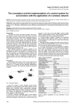
Fig. 10. Magnetic flux distribution in the cross section of GT40PCh6
synchronous generator as obtained from the 2D FEM.
Fig. 9. Wound-field air-cooled synchronous generator GT40PCh6:
1 – armature core of main generator, 2 – armature winding of
main generator, 3 – armature winding of exciter, 4 – armature core
of exciter, 5 – field winding of exciter, 6 – pole, 7 – field excitation system of exciter, 8 – rotor pole of main generator, 9 – armature of subexciter, 10 – PM, 11 – armature winding of subexciter, 12 – end shield, 13 – nozzle, 14 – housing, 15 – bearing,
16 – hollow shaft of rotor, 17 – shaft end, 18 – flanges, 19 –
fan, 20 – field winding of main generator, 21 – point of lubrication.
http://s010.radikal.ru/i314/1010/42/cba147b70185.jpg
the ball bearing. The bearing nest has a pocket for the collection of waste grease that is removed from it with the aid of
a plunger. Lubricant is applied to the bearing on the oil line
through the point of lubrication.
There are longitudinal ribs on the inner surface of the
housing, which increase its rigidity and form channels for passage of cooling air. Windows in the enclosure at the drive side
are designed to exit the air. Titanium flange screwed to the
end shield mounts the generator on the engine (Fig. 9). A
box on the outer surface of the housing contains a differential
current transformer for protection of the generator.
The rotor has two ball bearings. Seals of the bearings
are threaded type with extra cuffs. The rotor salient poles,
armature of the exciter and PMs of subexciter are pressed
on the hollow shaft. The rotating passive rectifier consists of
six silicon diodes D232A.
Cooling of the generator is accomplished by blowing air
at a flow rate varying from 0.1 to 0.3 kg/s.
Dimensions, material data and winding diagrams of the
GT40PCh6 synchronous generator are not available [3, 13,
10]. To obtain dimensions, winding parameters and detailed
303
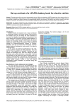
Fig. 11. Open circuit characteristics at synchronous speed ns =
const obtained from analytical calculations and 2D FEM.
performance characteristics of the GT40PCh6 synchronous
generator (Table 2), a reverse design on the basis of available sources [3, 10, 13] has been done. The 2D FEM has
been used for electromagnetic analysis and synthesis. The
2D magnetic flux distribution in the cross section of the main
generator as obtained from the FEM is shown in Fig. 10.
The open circuit characteristics [3] at synchronous
speed ns = f /p = const obtained from analytical calculations and 2D FEM are shown in Fig. 11.
Short-circuit currents can exceed more than 11 times
the nominal current. Figs 12 to 15 shows the armature
current Iash = f(t) waveforms for three-phase, line-to-line,
line-to-neutral and two lines-to-neutral short circuits of the
GT40PCh6 synchronous generator. The most dangerous are
line-to-neutral (Fig. 14) and two lines-to-neutral (Fig. 15)
short circuits. The obtained short-circuit current waveforms
are very important since the subtransient and transient shortcircuit currents help to evaluate the possible damage during
the electrical power system failure.
Fuel supply system
Civil transport aircraft use the wing structure as an integral fuel tank to store fuel. In larger aircraft, the fuel is also
stored in the structural wing box within the fuselage. A typical wing tank is irregular, long and shallow [7]. The fuel is in
direct contact with the outside skin. The Tu-154M has six fuel
tanks: one central fuel tank (CWT) No 1, two inner wing tanks
No 2, two outer wing tanks No 3 and one additional tank No
4. The Tu-154M fuel tank configuration is shown in Figs 16
PRZEGLAD
˛ ELEKTROTECHNICZNY , ISSN 0033-2097, R. 89 NR 2a/2013
Fig. 12.
Armature current Iash at three-phase short circuit of
GT40PCh6 synchronous generator. The peak current is 911.2 A at
0.9 ms.
Fig. 15. Armature current Iash at two lines-to-neutral short circuit of
GT40PCh6 synchronous generator. The peak current is 1130 A at
0.6 ms.
Table 2. Parameters of GT40PCh6 synchronous generator
Fig. 13.
Armature current Iash at line-to-line short circuit of
GT40PCh6 synchronous generator. The peak current is 944.6 A at
0.95 ms.
and 17. The tanks No 3 are between spars 1 and 3 and ribs
14 and 45 of detachable parts of wings [12].
The CWT tank is generally categorized as hazardous
due to the proximity to external heat sources, e.g., airconditiong units [7]. It requires tank inerting with the aid of
nitrogen-enriched air from the on-board inert gas generating
system. The tanks No 1 and 4 of the Tu-154M are inerted
in the case of emergency landing without landing gears. The
left and right wing tanks are usually categorized as nonhazardous as there is mostly no proximity of heat sources [7].
The wing leading edge slat section is equipped with anti-ice
control system, typically with hot air ducts. These ducts take
form of pipes with holes to allow air to heat the inner surface
Fig. 14. Armature current Iash at line-to-neutral short circuit of
GT40PCh6 synchronous generator. The peak current is 1108.2 A
at 0.95 ms.
Stator
Number of phases
3
Connection
Wye
Rated speed, rpm
6000
Rated frequency, Hz
400
Stator phase voltage, V
115
Stator rated current, A
111
Armature winding resistance per phase
at 25◦ C
0.0264
Base impedance, Ω
0.9919
d-axis synchronous reactance, p.u.
1.954
q-axis synchronous reactance, p.u.
0.776
Rotor
salient
Type of rotor
pole
Pole arc-to-pole pitch ratio
0.58
Number of poles
8
DC field current at nominal load
and PF=0.75, A
45.58
Total moment of inertia, kgm2
approx.
0.06
of leading edges. The hot air flow to the outer wing leading edges is controlled by the wing anti-ice valve [7]. The
Tu-154M has electric anti-ice control system with heating elements embedded in slats.
The fuel system of the Tu-154M uses electric motor
driven centrifugal pumps ECN-319, ECN-323 and ECN-325.
Fuel pumps ECN-323 and ECN-325 are driven by 115/220-V
AC induction motors (Fig. 18) and fuel pumps ECN-319 are
driven by DC 27-V brush motors (Table 3). A flange mounted
motor and pump constitute one integral unit (Fig. 19a). The
feeding cables in fuel tanks are in aluminum tubes (Fig. 19b).
Wiring system that delivers electric energy to fuel pump motors must be protected against electrical arcing and accumulation of static electricity that under some circumstances can
cause ignition of the fuel-air mixture in the wing tank [6, 7, 9].
In general, there are two types of fuel pumps on typical
aircraft [7]:
• Fuel transfer pumps (e.g., ECN-323, which perform the
task of transferring fuel between the aircraft fuel tanks to
ensure that the engine fuel feed requirement is satisfied;
• Fuel booster pumps (e.g., ECN-319, ECN-325) also
called engine feed pumps, which are used to boost the
fuel flow from the aircraft fuel system to the engine.
PRZEGLAD
˛ ELEKTROTECHNICZNY, ISSN 0033-2097, R. 89 NR 2a/2013
304
Fig. 16. Tu-154M fuel tank configuration: No 1 – center wing tank
(CWT), i.e., collector tank, No 2 – inner left and right wing tank, No 3
– outer left and right wing tank, No 4 – additional tank [12].
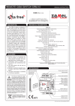
Table 3. Fuel pumps of Tu-154M.
Specifications
ECN-319 ECN-323 ECN-325
Type
Emergency
of pump
booster
Transfer Booster
Number of pumps
2
12
4
Electric
DC
Induction Induction
motor
brush
(cage)
(cage)
Voltage, V
27
115/200 115/200
Rated
current A
< 15
< 2.6
< 8.3
Starting
current
unknown
< 15.6
49.8
Pressure
drop, kG/cm2
1.6
0.45
1.25
Flow, l/h
1,500
2,000
3,500
... 7,000 ... 12,000
Mass
of pump, kg
3.8
4.0
5.8
Commercial aircraft use open vent system to connect the
ullage1 in each tank to the outside air [7]. The Tu-154M is
equipped with the vent system.
The Tu-154 uses fuel Jet A-1. Jet A-1 is a kerosene
grade of fuel suitable for most aircraft turbine engines. It is
produced to a stringent internationally agreed standard.
Wing anti-ice system
Most civil aircraft use hot bleed air for anti-ice control of
outer wing leading edges [7]. The Tu-154M must use electric
resistive heating for anti-ice of the wing leading edge slats, as
the turbofan engines are tail mounted and located far away
from the wings. This would make the hot air bleed system
very heavy and cumbersome.
The Tu-154M has three-phase, 115-V electrical wing
anti-ice heating system (Fig. 20) [3, 9, 14]. To save electrical energy, heating elements are fed cyclically by adequate
determination of time period. Under cyclic heating a thin layer
of ice accumulates on slats which does not deteriorate aerodynamic properties of the aircraft. When the accumulation
reaches a thickness threshold and the temperature of skin
increases, the ice is taken out by the air stream.
The generator GT40PCh6 No 2 driven by the mid turbofan engine (Fig. 5) feeds only the electric grid 2 dedicated to
heating wing slats. The electric apparent power is 43.6 kVA
at 115 V (phase voltage) and ≤ 130 A.
Heating elements (composites) of one half of slats are
divided into eight sections. The other half of slats has also
eight sections. Section are fed in the following sequence:
1 Space
305
between the fuel surface and upper wall of the tank.
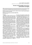
Fig. 17. Tu-154M fuel system layout. Fuel tanks, fuel pumps, fuel
transfer lines, D30KU engine and APU have been shown. 1,2 – feed
lines of upper transfer from tanks No 4 and 1 to tank No 2; 3 – faucet
of reserve transfer; 4 – antifire faucet; 5 – discharge faucet, 6 – connector for maintenance of engines [12, 16].
Fig. 18. Layout of ECN-323 and ECN-325 fuel pumps. 1 – tank, 2 outlet, 3 – axial wheel, 4 – collection snail, 5 – impeller, 6,7 – safety
grid, 8 – connecting channel, 9 – electric motor, 10 – circulation orifice [12].
1st , 2nd , . . . 8th , 1st , 2nd , . . . 8th . . . . Sections are numbered
starting from the core part of the wing to the end of the wing.
The current is on for 38.5 s and off for 269.5 s for each section.
In the leading part a thermal “knife” is installed along
the slats. This part is made of 20-mm wide X20H80 NiCr
foil. The thermal “knife” is not fed cyclically – it is steadily
under current and is isolated from the outer skin by three
layers of glass fiber 3 (Fig. 20). Also, the three layers 5
isolate the thermal “knife” from the heating element. On the
inner skin/sheathing of heating element of the slat, thermal
switches for cyclic operation of sections and thermal “knife”
are installed. Thermal switches protect slats and heating elements against overheating.
Lighting
The lighting equipment of the Tu-154M is divided into
external and internal equipment. External equipment is intended for taxiing, takeoff, landing, and indicate the plane in
the air space at night. Interior equipment is used for illumination of the cockpit, passenger cabin and other chambers of
aircraft, and emergency lighting.
The external lighting equipment includes wing navigation
(position) lights BANO-57 with 70-W SM-28-70 lamps, 115 V
SMI-2KM anticollision flashing lights (45 flares/min), and 27
V, 35.5 A PRF-4 landing/taxi lights.
The cockpit is equipped with a general illumination systems and lamps for lighting control boards, panel of flight en-
PRZEGLAD
˛ ELEKTROTECHNICZNY , ISSN 0033-2097, R. 89 NR 2a/2013
Failures of electric power system
Failures of synchronous generators
The mean time between failures (MTBF) of GT40PCh6 synchronous generators is estimated as approximately 8000 to
8500 flight hours [2, 3, 13, 16].
Fig. 19. Booster fuel pump ECN-325: (a) cross section of fuel pump
and induction motor; (b) feeding cable tubing. 1 – grid, 2 – induction
motor, 3 – motor housing, 4 – shaft, 5 – tube, 6,7 – sealing rubber rings, 8 – pump housing, 9 – rotor, 10 – cover, 11 – snail, 12 –
impeller, 13 – channel, 27 – conduit metal tube, 28 – tubing, 29 – terminal block, 30 – cover, 31 – electric cable. Construction of transfer
fuel pump ECN-323 is similar [3, 9, 12].
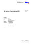
Fig. 21. Tail part of Tu-154B-2 RA-85588 after fire at Surgut airport
on January 1, 2011 [2].
Fig. 20. Leading edge wing anti-ice system: 1 – slat, 2 – outer
skin/sheathing, 3, 5, 7 – thermal glass insulation, 4 – thermal “knife”,
6 – heating element, 8 – inner skin/sheathing [9, 14].
gineer, top switchboard, middle console of pilots, aircraft panels, panels of automatic pressure control, workplace of navigator, etc. In addition, each crew member has lamps with a
red cylindrical optical filter that allows the light to change from
white to red.
General illumination of passenger cabins has been designed in form of central and side fixtures with fluorescent
lamps. Each central fixture has two fluorescent lamps contained in the reflector and sealed with milky color plexiglas.
Side lights are built-in into the lower panels of luggage bins.
Individual passenger lamps equipped with lenses to focus the
ligh beam are used at night after turning off the lights of the
passenger compartment. Lamps are mounted in the bottom
panel of luggage bins. Single-lamp fixtures are mounted in
the toilets, hallways, kitchenette and above the mirrors.
Emergency lighting is provided to illuminate the passenger areas on the ground when the power is supplied from the
on-board batteries. During flight, the emergency lighting of
passenger cabins is turned on at night after turning off the
general illumination. Emergency lighting is installed in passenger cabins, lobbies, dressing rooms and toilet passages.
Fig. 22. Closed electric circuit on assumption of abnormal scenario
corresponding to 21st contactor TKS233DOD “switching generator
No 3 on grid” [2].
There is known at least one case of main generator failure, i.e., the Tu-154B-2 RA-85588 while operating flight 7K
348 on January 1, 2011 from Surgut to Moscow (Domodedovo). The plane was taxiing to the runway while preparing
for its takeoff from Surgut when the right engine caught fire
on the taxiway (Fig. 21). Three out of 126 passengers and 8
crew members died.
Russia’s Interstate Aviation Committee (MAK) released
their final report (in Russian) concluding the probable cause
of the accident was the outbreak of fire in the right generator panel located between frames 62 and 64 in the cabin [2].
The generators were connected on the network after the engine start and exit to the idle mode. The cause of the fire
was an electrical arcing produced by electrical currents exceeding 10 to 12 times the nominal current when two generators not synchronized with each other were brought online
but got connected together instead of being connected to parallel busses (Fig. 22). The unsynchronized operation of the
generators can be attributed to:
1. Poor technical conditions of contacts TKS233DOD (Fig.
22) responsible for connecting the generators with the
electrical busses, that were damaged by prolonged operation without maintenance. A contact normally open
was welded and fractured insulation material moved between contacts that are normally closed. These abnor-
PRZEGLAD
˛ ELEKTROTECHNICZNY, ISSN 0033-2097, R. 89 NR 2a/2013
306
mal contact positions led to the connection between No
2 and No 3 generators (Fig. 22).
2. Differences in the schematic diagrams of generator No 2
and generators No 1 and 3. When the switch is moved
from "check" to "enable" with no delay in the "neutral"
position, the generator 2 is brought on line without time
delay. This leads to increased wear of normally closed
contacts in the TKS233DOD unit. The specific design
of the electrical systems ensures power supply to each
bus from either the APU or engine integrated drive generator.
Failures of other electrical equipment
On September 7, 2010, the Tu-154M RA-85684 Alrosa Mirny
Air Enterprise Flight 514 aircraft from Udachny to Moscow
suffered a complete electrical failure en route, leading to a
loss of navigational systems. The electrically operated fuel
transfer pumps were also affected and prevented transfer of
fuel from the wing tanks to the engine supply tank in the fuselage.
After emergency decent below cloud level the crew were
able to spot an abandoned air strip near town of Izhma (Fig.
23). The abandoned air strip is 1325 m, whereas the Tu154 requires a minimum of 2200 m. The aircraft landed at
a speed of 350 to 380 km/h, faster than normal, due to the
lack of flaps. Although the flaps are powered by hydraulics,
the switches operating them are electrical. The impact was
damped by the young trees, which have grown since the airport was closed. All nine crew members and 72 passengers
evacuated using the aircraft’s evacuation slides. No injuries
were reported.
Fig. 23.
Emergency landing of Tu-154M RA85684 at abandoned air strip near town of Izhma on
September 7,
2010.
http://www.airlinereporter.com/wpcontent/uploads/2011/11/TU154a.jpg
On November 17, 1990, the cargo TU-154M, CCCP85664 of Aeroflot Airways was heading through Czech territory with a load of Winston cigarettes from Basel to Moscow.
A switched-on cooker in the kitchenette caused a fire on
board of the plane and the crew decided to land at the closest possible place. The crew made an attempt of emergency
landing on the field near Dubenec village in the East Bohemia. There were only 6 crew members on board, all of
them survived the air disaster.
On February 18, 1978, the Tu-154A, CCCP-85087 of
Aeroflot Airways was standing on the apron at Tolmachevo
Airport, Novosibirsk. The cabin heater was left working unattended between flights. A rag caught fire, which incinerated
the cabin. A fire that broke out in the passenger cabin en-
307
gulfed the rear part of the airframe. The forward fuselage
burnt out. There were no fatalities.
Conclusions
The electric system of the Tu-154M aircraft is an outdated system typical for aircraft being designed in the 1960s.
There are three GT40PCh6 wound-field synchronous generators driven by D-30KU low-bypass turbofan engines and one
GT40PCh6 generator driven by the TA-6A APU turboshaft
engine. The APU is also equipped with the 27 V DC GS12TO starter generator. The Tu-154M is not equipped with a
RAT.
Main synchronous generators GT40PCh6 are air cooled
generators. Air cooling reduces the rated power and increases the mass of generators. Nowadays, modern VSCF
wound-field synchronous generators are oil cooled with rated
power up to 250 kVA (Boeing 787 Dreamliner ).
Reversed design and analysis of GT40PCh6 main synchronous generators deliver important information on steadystate and transient performance of these machines. Transient characteristics, especially short-circuit waveforms are
very helpful in investigation of electric power system after
malfunction, failure or crash.
BIBLIOGRAPHY
[1] Ellis G.: Air crash investigation of general aviation aircraft,
Greybull, WY, USA, Capstan Publications, 1984.
[2] Final Report on results of investigation of aviation accident
involving the Tu-154B-2, tail number RA-85588, airport Surgut,
on January 1, 2011, in Russian, Interstate Aviation Committee
(MAK), Moscow, 2011.
[3] Electrical equipment of aircraft Tu-154B(M), in Russian, Rilsk,
Aviation College of Technology, 2000.
[4] Gieras JF.: Advancements in electric machines, LondonBoston-Dordrecht, Springer, 2008.
[5] Hill R., Hughes W.J.: “A review of flammability hazard of
Jet A fuel vapor in civil transport aircraft fuel tanks”, Report DOT/FAA/AR-98/26, US Dept of Transp., Springfield, VA,
1998.
[6] Kosvic T.C., Zung L.B., Gersten M.: “Analysis of fuel tank fire
and explosion hazards”, Technical Report AFAPL-TR-71-7, Air
Force Propulsion Laboratory, WPAFB, Ohio, 1971.
[7] Moir I., Seabridge A.: Aircraft systemes: mechanical, electrical and avionics subsystems integration, 3rd ed., Chichester,
UK,J. Wiley & Sons, 2008.
[8] Ronkowski M., Michna, M., Kostro, G., Kutt, F.: Electrical machines around us, in Polish, Gdansk University of Technology,
Gdansk, Poland, 2011.
[9] Soshin, V.M.: Aircraft Tu-154M, book 2, ed. Samara State
Aerospace University, Samara, 2005.
[10] Timofieyev, J.M.: Electrical equipment of Tu-154M aircraft,
Federal Air Transport Service of Russia, Academy of Civil Aviation, Sankt-Petersburg, 2000.
[11] Tu-154. Catalogue of parts and compilation of units. Chapter
27: Control, in Russian, Avia-Media, 1984, updated 2003.
[12] Tu-154M. User’s technical guidance, Chpt. 28. Fuel system.
[13] Tu-154B. User’s and technical service manual, Book 7, Part 1.
Electric equipment, in Russian, Samara, Aviakor, 1994.
[14]
Wing of Tu-154 aircraft,
in Russian,
Virtual
cabinet of aircraft construction,
[web page]
http://cnit.ssau.ru/virt{\_}lab/krilo/index.htm
[Accessed on Nov. 28, 2012].
[15] Wood R.H., SweginnisR.W.: Aircraft accident investigation,
2nd ed., Casper, WY, USA, Endeavor Books, 2006.
[16] Znichenko V.I: Construction and user manual of Tu-154M
aircraft, Federal Air Transport Service of Russia, NLMK,
Academy of Civil Aviation, Sankt Petersburg. 1998.
Authors: Prof. Jacek F. Gieras, Ph.D., D.Sc., IEEE Fellow, Department of Electrical Engineering, Electrical Machines and Drives, University of Technology and Life Sciences, Al. S. Kaliskiego 7, 85-796 Bydgoszcz, Poland, email:
[email protected]
PRZEGLAD
˛ ELEKTROTECHNICZNY, ISSN 0033-2097, R. 89 NR 2a/2013