1
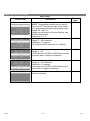
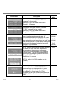
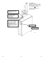
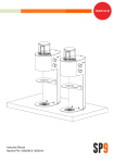
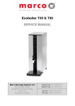
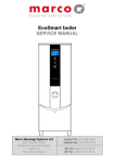
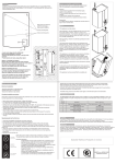
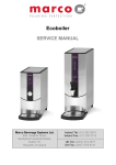
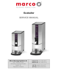
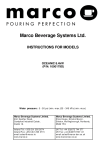
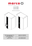
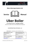
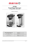
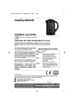
Marco Beverage Systems Ltd. INSTRUCTIONS FOR MODELS Ecoboiler UC4L 2.4kW (1000740#) Ecoboiler UC10L 2.8kW (1000741#) Ecoboiler UC10L 5.6kW (1000742#) Ecosmart UC4L 2.4kW (1000750#) Ecosmart UC10L 2.8kW (1000751#) Ecosmart UC10L 5.6kW (1000752#) (where # is either blank or a suffix of one or more alphanumeric characters) E337347 NSF/ANSI 4 Water pressure: 5 - 50 psi (min.-max.)35 - 345 kPa (min.-max.) Marco Beverage Systems Limited. 63d Heather Road, Sandyford Industrial Estate, Dublin 18. Marco Beverage Systems Limited. Shire House, Strixton Manor, Strixton, Wellingborough, Northants, NN29 7PA Ireland Tel: +353 (0)1 295 2674 Ireland Fax: +353 (0)1 295 3715 Email: [email protected] www.marco.ie UK Tel: +44 (0)2072 744 577 UK Fax: +44 (0)2079 788 141 Email: [email protected] www.marco-bev.co.uk SAFETY: This appliance must be earthed. If the moulded plug supplied is not used then ensure that the green/yellow cable is connected to a suitable earth. Risk of flooding. The hose supplied with this unit is non-toxic food quality tested to 190psi. However, a hose is not a permanent connection. It is, therefore, advisable to switch off boiler and close the stopcock valve when boiler is not in use, e.g. overnight, weekends etc. Risk of scalding. The utmost care has been taken in the manufacture and testing of this unit. Failure to install, maintain and / or operate this boiler according to the manufacturer’s instructions may result in conditions that can cause injury or damage to property. If in any doubt about the serviceability of the boiler always contact the manufacturer or your own supplier for advice. This appliance is not intended for use by persons (including children) with reduced physical, sensory, or mental capabilities, or lack of experience and knowledge, unless they have been given supervision or instruction concerning use of the appliance by a person responsible for their safety. Children should be supervised to ensure that they do not play with the appliance In the event any wires are damaged, such wires can only be replaced by experts or professional after service staff from the manufacturer, after service department or similar function departments INSTALLATION DETAILS: Electrical installation: When installing the product, always observe the local regulations and standards. Products without an electrical plug are to be connected by an authorised professional installer. Power supply (V) 220 230 240 2.4kW version Power Ratings 2.2kW 2.4kW 2.6kW 2.8kW Versions Power Ratings 2.6kW 2.8kW 3.0kW 5.6kW Versions Power Ratings 5.2kW 5.6kW 6.0kW Plumbing installation procedure: Mains water pressure required (limits): 5-50psi (35-345kPa) Fit a stop Valve on a cold water line and attach a 3/4" BSP male fitting, (e.g. 3/4" x 1/2" 311 or washing machine type stop valve). For US versions use 3/8” NPT male fitting Connect straight tailpiece of the hose to the stop valve fitting. Make sure that the pre-attached sealing washer is fitted. Turn on the water to flush any impurities, dust etc from the inlet hose and water pipe. Allow several gallons through. Connect right-angled tailpiece of the hose to the inlet valve of the boiler (again 3/4" BSP). Make sure the sealing washer is fitted here also. Turn on water and check for leaks. If the overflow vent is plumbed it must be plumbed with a tundish device. This equipment must be installed with adequate backflow protection to comply with all applicable federal, state and local codes. Operating boiler for the first time: Check that all installation procedures have been carried out. Ensure water valve is on. Plug boiler appropriate electrical supply and press power button on the front of the machine marked ‘Power’. Refer to Figure 1. 1900052 REV.6 Page 2 The “power on” light will glow green and the machine will fill to a safe level, above the elements, before heating. The “Ready/Status” light will cycle two red flashes while the machine is filling to the safe level. After this amount of water has heated to about 95ºC the boiler will draw more water in until the temperature drops by 1 or 2 degrees. The boiler will then heat again. This heat fill cycle continues until the boiler is full. Whilst the machine is above the safe level and filling, the “Ready/Status” light will remain blank. The “Ready/Status” light will glow green when the machine is both full and up to normal operating temperature. The boiler is now ready for use. NOTE: Because the boiler is electronically controlled no priming is necessary. The element cannot switch on until a safe level of water is reached. ECO Mode Operation (10L machines onl y): All ECO Boilers use high grade insulation and it is applied to give a significant energy usage improvement over a standard water boiler. All under counters incorporate a ½ tank ‘ECO mode’ function. To enable the ‘ECO Mode’ press the button located below the ‘Ready’ indicator so that the leaf symbol illuminates green. This mode saves energy by minimising the energy wasted during machine down-time. NOTE: The ECO mode is most effective in installations where the machine has a regular ‘off’ period. To achieve the most benefit from the energy saving ‘ECO Mode’ on your ECO boiler unit (10L variants only), the following method should be employed: o Towards the end of the boilers operating period for a given day, switch the machine to ECO Mode. Whilst maintaining water at 95oC, the machine tank will slowly drop to half full, where it will remain. o At the end of the machines operating period it should the be turned ‘off’. o During the ‘off’ period as there is less water in the tank there will be less energy lost to the surrounding environment resulting in an energy saving. To disable simply press the ‘ECO Mode’ button again so that the leaf symbol is not illuminated Power Button Ready/Status Indicator Ecomode Button 1900052 REV.6 Page 3 EcoSmart Features (ECOSMART MACHINES ONLY) : The EcoSmart Ecoboiler has many settable features which gives the operator great flexibil ity in choosing how the unit will operate. The following explains how the various features may be changed and their function. There are two Menus in the EcoSmart Boiler One is to set the USER SETUP and One is to set the SERVICE SETUP parameter. HOW TO SETUP AN EcoSMART: Smart Boiler (software Revision 1.10) After few seconds the display will show the main screen: Welcome screen with version number Main screen Top part of the display always shows live read-out of the tank temperature (0.5°C accuracy). Bottom part shows current machine status. Entering Setup Mode To enter setup mode press power and eco buttons on the front panel at the same time. The display will show “USER SETUP” message: Release the buttons now to enter the user setup mode. To enter advanced settings keep the buttons pressed until the display shows “SERVICE SETUP” message and release them. In both setup modes use front panel buttons to navigate the settings: o power button to scroll through the functions, o eco button to increase set value (press and hold for auto-repeat). 1900052 REV.6 Page 4 USER SET UP OPTIONS: User Setup Screen view Description Sets new tank temperature. NOTE: Temperature should never be set for more than 97°C because it may cause steam to be generated during the low pressure days. Range: 60 – 98.5 °C Range can be limited in Service Settings, see Service Setup below. Resolution: 0.5 °C Sets dispense time. Range: 0 – 99.9 seconds Resolution: 0.1 second For PUSH & HOLD mode set to 0 (default). 1900052 Default value 95.0 00.0 Sets number of pauses during time dispense. Range: 0 – 20 If machine set as PUSH & HOLD then number of pauses has no impact on dispense. 00 Sets pause time (same for each of the pauses). Range: 0 – 20.0 seconds Resolution: 0.1 second If machine set as PUSH & HOLD then time of pause has no impact on dispense. 00.0 Press the eco button to save all the values and reset the machine. - REV.6 Page 5 SERVICE SETUP OPTIONS: Screen view Description No. 1 Sets and shows remaining weeks before de-scaling is needed (“DESCALE TANK” message on the screen). Setting it to OFF will disable the function. Range: 1 – 60 weeks Default value OFF No. 2 Sets and shows remaining litres of water before filter change is needed (“CHANGE FILTER” message on the screen). Setting it to OFF will disable the function. Range: 100 – 9900 litres OFF No. 3 Sets the time for which the inlet opens every time the machine needs water. It minimises temperature fluctuations. The value should be picked to allow 0.5 - 1°C cooling after water intake and depends on the tank size and element power. This is a factory setting and should only be changed by trained personnel. Range: 0 – 20.0 seconds Resolution: 0.1 second No. 4 Sets the time at which machine waits for the water too cool down after water intake. Measured from the beginning of the water intake. The value depends on tank size and element power. This is a factory setting and should only be changed by trained personnel. Range: 0 – 60.0 seconds Resolution: 0.5 second No. 5 “SERV PIN” limits access to SERVICE SETUP, setting it to 0000 disables the pin (default) 3.0 (2.8kW) 6.0 (5.6kW) 9.0 (8.4kW) 12.0 OFF No. 6 PIN entry screen - once PIN is set and user wants to access SERVICE SETUP this screen will pop up; use top button to move through positions and bottom to scroll through the values (0 to 9 and again 0); if PIN is accepted you will gain access to the SERVICE SETUP, if PIN is rejected machine will reset itself. 1900052 REV.6 Page 6 No. 7 Sets the mode the machine works in: HEAT FILL (default – minimises temperature fluctuations), CONT FILL (continuous fill – makes sure the tank is always full but temperature may vary), COOL FILL (allows cooling but reduces tank size by using ECO mode), MANUAL (manual filling). See further explanations pg 8 No. 8 Sets temperature units on screen. No.9 This sets max limit of the temperature that user can set in USER SETUP; max value is 98.5 deg C No.10 Press the eco button to save all the values and reset the machine. HEAT FILL Celsius Celsius - DISPLAY INFORMATION DESCRIPTIONS: Status Description Machine off. Display backlight off but temperature readBOILER OFF out still working. Water level below low level probe. Machine is filling FILLING ... automatically. Status LED – 2 red blinks. Water level below low level probe. Machine has to be refilled manually (shown only in MANUAL mode). FILL THE TANK Status LED – 2 red blinks. WAIT ... Water is being heated. Dispense valve disabled. Water is up to the temperature and can be used. Note that this only means that the tank is heated and not that it is BOILER READY full. Status LED – green. Water is being dispensed. If machine is set to time dispenses – there will also be a progress bar drawn DISPENSE underneath. Dispense can always be cancelled by clicking the dispense button again. Machine was set by the user to a lower temperature than the current tank temperature and is trying to cool down by taking in more cold water. This process may take between COOLING ... 20 seconds to a few minutes depending on tank size and temperature difference. Works only in COOL FILL mode. 1900052 REV.6 Page 7 DISPENSE WATER TO COOL THE TANK DESCALE TANK CHANGE FILTER CHECK LOW PROBE THERMISTOR S/C ELEMENT FAILURE THERMISTOR O/C LOW PRESSURE COMM ERROR Machine can not take more cold water to cool the tank because it is full. Water needs to be dispensed to allow room for more cold water to come in and finish cooling process. Descale timer elapsed. Time to descale the tank. Litres output exceeds set value. Time to change the water filter. Low water level probe broken (disconnected). Machine detects high level probe signal but can not detect low level one. Filling is disabled. Status LED – 1 red flash. Temperature sensor (thermistor) is short circuited. Dispense and heater disabled. Status LED – 3 red flashes. Heating element is broken. Error is triggered when after 20 minutes of heating and not taking in water temperature in the tank fails to increase. Dispense is disabled. Status LED – 4 flashes. Temperature sensor (thermistor) is disconnected. Dispense and heater disabled. Status LED – 5 red flashes. Incoming water pressure too low. The error will be reset after water supply restores. All boiler functions are active. Status LED – 6 flashes. Display board lost communication with boiler PCB (can not receive serial data about temperature and probes). All actions cancelled. Modes of Operations [Service setup setting 5 ]: Modes of OPERATION - This boiler can operate in 3 different modes. HEAT FILL – Standard operation the boiler will take in water until the temperature in the tank drops, the inlet will close and the heating element is activated. W hen the temperature reaches the set temperature the inlet will reopen to take in more water. This cycle will continue until the Tank is Full. This mode is used to ensure that the water temperature is controlled within set values. CONTINUOUS MODE – In this mode the boiler will take in water and activate the element until the tank is full and the temperature has reached the set temperature. Typically used in high demand situations where the temperature stability is not primary concern. COOL Mode – In this mode the temperature can be adjusted up or down [function 1.] while in operation. Depending on the water level in the tank selecting a lower temperature will cause either a message to “DISPENSE W ATER TO COOL THE TANK” or will automatically take in cooler water to reduce the temperature to the new set temperature. In applications where selecting different temperatures frequently is required this Cool Mode is best selected. 1900052 REV.6 Page 8 Note in the Cool Mode will cause the 10L boiler to operate as a 5L boiler and cause the 4L boiler to operate at 2L. MANUAL FILL – if the boiler is not plumbed into a water sup ply the operator must select Manual Fill mode for best operation of the boiler. In this mode the water is added manually by the operator. ECO Mode Operation: Note In the COOL FILL mode [see Service setup setting 5] the ECO Mode is automatically selecte d. All ECO Boilers use high grade insulation and it is applied to give a significant energy usage improvement over a standard water boiler. The under counter range incorporates a ½ tank ‘ECO mode’ function. To enable the ‘ECO Mode’ press the button located below the ‘Ready’ indicator so that the leaf symbol illuminates green. This mode saves energy by minimising the energy wasted during machine down-time. NOTE: The ECO mode is most effective in installations where the machine has a regular ‘off’ period. To achieve the most benefit from the energy saving ‘ECO Mode’ on your ECO boiler unit (10L variants only), the following method should be employed: o Towards the end of the boilers operating period for a given day, switch the machine to ECO Mode. Whilst maintaining water at 96oC, the machine tank will slowly drop to half full, where it will remain. o At the end of the machines operating period it should the be turned ‘off’. o During the ‘off’ period as there is less water in the tank there will be less energy lost to the surrounding environment resulting in an energy saving. To disable simply press the ‘ECO Mode’ button again so that the leaf symbol is not illuminated TROUBLESHOOTING: The Ready/Status light signals various errors or problems. A cycle of red flashes indicates an error. The number of flashes in a cycle corresponds to the symptom in the table below: Status/Diagnostic light guide: No of Symptom flashes Water level below elements. Normal 2 when machine first fills. 3 Temperature sensor failure (o/c) 4 Water not heating 5 Temperature sensor failure (s/c) 6 Machine not filling Action required Check water pressure , if this is OK then call service agent. Call service agent Call service agent Call service agent Check water pressure, if OK then call service agent. MAINTENANCE: This machine has been designed to give many years of trouble free service. The only regular maintenance required is occasional de-scaling. Descaling Procedure: Isolate machine from power supply. 1900052 REV.6 Page 9 Isolate machine from water supply. ALLOW TO COOL COMPLETELY! Drain water from machine. Remove all lids. Remove as much scale as possible by hand, paying particular attention to level probes (White plastic with steel tab). Be very careful not to damage any attachments. Use ScaleKleen, Marco part No. 8000270 or similar. Follow instructions carefully. Thoroughly clean and flush the machine before re-use. Follow installation and first time operation instructions. ACCESS TO INTERNAL COMPONENTS: UC10L 1900052 REV.6 Page 10 UC4L Disconnect the machine from the electrical supply. Allow to cool sufficiently. On the 10L machine insert a flat headed screwdriver at the four locations indicated on the picture above and rotate. Note: - There is no need to ‘lever’ the screwdriver – a small rotation is all that is required. In the case of the 4L machine remove the 4 screws on the service panel located on the right hand side. Place the panel to the side of the machine. This allows access to most of the internal components and the machine does not need to be drained for most maintenance or service operations. The Tank can be drained by removing the plug from the end of the drain hose, and draining into an external drain or a large enough container. FONT INSTALLATION: The font is connected to the machine by a silicone hose and a control wire. The button on the font triggers the pump in either push and hold or push and release mode. Please refer to separate calibration instruction for setting of these modes. The calibration should only be conducted by a trained service engineer. The font’s silicone hose should be connected to the boiler hose adapter and secured with the supplied hose clip. The Boiler ideally should be positioned directly below the font installed position. To help prevent heat loss between the tank and the dispense font, the silicone hose should be insulated with the supplied hose insulation. Simply cut the insulation to the correct length required. Standard Font Connection 1900052 REV.6 *Font will vary. Depending on font the type the drip tray will either have to be manually emptied Or Page 11 Connected to a drain via drip tray outlet. Font connection with ball valve 2- wire Electrical Connection Font to Boiler Vent may be plumbed to a drain – however there must be an air gap to prevent the possibility of a blocked drain flowing into the boiler. Controls Service Panel UC 10L 1900052 REV.6 Page 12 *Font will vary. Depending on font the type the drip tray will either have to be manually emptied Or Connected to a drain via drip tray outlet. Font connection with ball valve 2- Wire Electrical Connection Font to Boiler Vent may be plumbed to a drain – however there must be an air gap to prevent the possibility of a blocked drain flowing into the boiler. Controls Service Panel UC 4L 1900052 REV.6 Page 13 NSF Approved Font Connection In order to comply with NSF 4 requirements, when installing an NSF listed undercounter boiler with an NSF listed Uber Font, The Vent pipe on the boiler MUST be connected to the Font Vent hose (grey coloured hose). Font connection 2- wire Electrical Connection Font to Boiler Vent connection Controls Service Panel 1900052 REV.6 Page 14 CLEANING: The exterior of these machines may be cleaned with a damp cloth and a light detergent. Do not use abrasive cloths or creams, as this will spoil the finish of the machine. Do not use a water jet or spray. NB: Beware of accidentally operating the draw off tap or push button when cleaning the front of the machine. LIMESCALE: In common with all water boiler manufacturers, service calls resulting from lime scale are not covered by warranty. Fitting a scale reducer is recommended, especially in hard water areas. This can reduce the build-up of scale but may not stop it altogether. The frequency that descaling is required depends on the local water supply; hard water areas need more attention. Descaling of the machine should ideally be carried out by qualified service personnel. 1900052 REV.6 Page 15