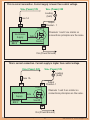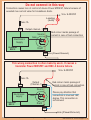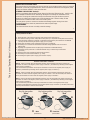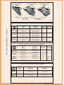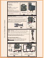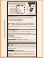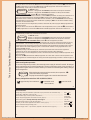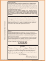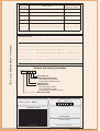
1
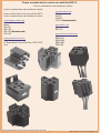
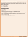
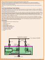
RSC-2
2 channel
remote control
www.LPRS.co.uk
[email protected]
1
RSC-2
2 Channel Remote Control
Designed to work with Keeloq
Update documents
2010-02-11 version 1.5
Operating Manual
& Application Notes
This is a booklet in pdf version to put on to www page
Before starting work, please read carefully the attached installation and configuration instructions.
We remind you that ignoring the principles and observations contained in the instructions could damage the device.
Suggested order of work:
? Check the power supply voltage; the battery attached to the RSC-2 has the appropriate parameters.
? Connect the cable to the Vss Ground (86) pin of the RSC-2 device.
? Connect the second power supply line Vcc + (85) pin to the second pole of the power.
? Connect the same wire to Vss Ground of the device
? Next you can connect outputs: 30 and 87 to the input of controlled device.
VERY IMPORTANT
Never connect the output of any channel when the RSC-2 does not have appropriate power supply connected.
If you want to connect or disconnect any other device to / from the controlled device or control (master and slave) disconnect
the power from both devices first.
Never connect the output channel when controller for the RSC-2 channel is lower than the voltage of the power-VCC (86) pin.
You can get around this problem by using an additional relay or diode corresponding voltage and current.
At the end the channel must be connected to the load control channel. If your device has a receiver superregenerative it is
recommended that the next assembly is a minimum of 3 m from the first one.
The superheterodyne receiver do not have this problem. Device with the superheterodyne receiver is marked differently.
You have to always remember that outputs: 30 and 87 ( see the bottom of RSC-2) have Power Transistors MOSFET N-channel
which have breakdown diode inside which works with inductive elements.
We recommend to apply breakdown diode outside between channel output (Anode) and +VCC supply (Katode)
The RSC-2 is adapted for mounting vertically (outputs down) so that water can’t damage the electronics of the device.
Standard cover unit is not a fully hermetic. You must not submerge it in water. The device is designed for outdoor use and it is
resistant to light flooding.
Devices which we have manufactured are resistant to light water immersion and work in the engine compartment and in
difficult conditions of moisture.
You must not solder wires directly to the output female TERMINALS. This can cause solder out terminals from the board and
the RSC-2 can be damaged.
For connections you should use female TERMINALS.
Operating Manual RSC-2 LPRS (version for web exclusively)11-02-2010R
2
www.LPRS.co.uk Email. [email protected]
Power sockets which can be use with the RSC-2.
Links to manufacturers and distributors website:
Links to manufacturers and distributors website:
www.skyrelays.com
Model:
Uc3001
Uc3003
Cs3770 (Recommended)
Power sockets which can be use with the RSC-2.
Links to manufacturers and distributors website:
www.huaguan-relays.com
Automotive relay socket
Model:
NVF4-S1
NVF4-S2
NVF4-S3 (Recommended)
NVF4-S5
www.nteinc.com
Model:
R95-160
www.customconnector.com
Model:
BR05-FW5
BR05-WH5
BR05-WHF
PR04-WH
www.mcmelectronics.com
Model:
PC Board Mount Socket 40A Relay 12VDC SPDT
5 pin
Operating Manual RSC-2 LPRS (version for web exclusively)11-02-2010R
3
www.LPRS.co.uk Email. [email protected]
We offer RSC-2 version with wires instead of male terminals
The 15 cm wire outside the casing tube is the antenna. This cable should not be shortened. It should be left loose in order to
have a good antenna factor to gain energy from the fob.
All equipment RSC-2 outputs are giving ground to the active channel. If the channel is turned off the output channel is high
impedance as if nothing was connected.
Numbers at the bottom of the RSC-2:
Number (86): GND supply (-)
Number (85) positive supply (+)
Number (87) output 1st channel
Number (30) output 2nd channel
Guarantees are not subject to:
v
v
v
v
v
v
v
v
Cause unit RSC-2
Batteries for fobs
Bundles and bundles of wires attached to the device.
In the case of loss or destruction of the warranty card, duplicates will not be issued
For damage resulting from damage to the automatic device, random events, actions of third parties or improper
installation LPRS Ltd accepts no material liability.
Properly fill out all points of the guarantee. Original signature of the customer is required when dealing with
complaints and repair within the warranty.
Flooded equipment is not repaired
The decision about the warranty made by LPRS Ltd is final.
Operating Manual RSC-2 LPRS (version for web exclusively)11-02-2010R
4
www.LPRS.co.uk Email. [email protected]
LPRS Ltd declare that the product is designed and constructed in accordance with:
Compliance with the requirements of the standard ETS 300 220-3 9/2009 and article 3 of the Directive 1999/5/EC
At the same time we ensure our customers that the devices have been designed and manufactured with great attention
to detail and maximising the performance.
In this device we apply the latest technology to make sure the device will work perfectly. Please have a look at the diagrams
below.
Self-Protected Intelligent Power Switches
Intelligent Power Switches (IPS) from International Rectifier integrate into a single package a low RDS(on) output HEXFET®
power MOSFET with protection and control circuits, making them the most rugged, efficient and compact devices available for
automotive loads in harsh environments.
The embedded charge pump makes the interface to the micro-controller very simple with full logic-level compatibility. Built-in
protection features, like over-temperature, over-current and active inductive energy clamp protect against short circuits, stalled
motors and excessive ambient temperature. Designed to safely handle ordinary overload conditions as well as several
extraordinary conditions, including loss of ground, load dump and reverse battery, IPS devices eliminate switch failures with
the best efficiency and no addition in part count.
Designs for low occurrence situations are minimised. The double level shifter circuitry that drives the MOSFET in the HighSide Switcher (HSS) provides immunity from large offsets between the logic ground and the load ground and short switching
times. Internal slew rate control for turn-on/off and the use of a low noise charge pump means lower EMI. Ground noise
generation of less than 10mA is the industry’s lowest figure.
Applications
v
v
v
v
v
v
v
v
v
v
Ideal replacement for electro-mechanical relays
Automotive
Transmission Controls
Junction Boxes
Electronic Stability Controls
Anti-lock Brakes, Traction Controls
Diesel and Gas Direct Injection
Pump Motors, Radiator Fans
Head Diesel Glow Plugs
Lamps
Connection example
Vcc+ (Power) 9-30V/DC
Channel loading
Fuse 1A
85
Output
channel -1
87
30
Drain
Drain
electronics
supply
Controller
RSC-2
Output
channel -2
Gate
Gate
Source
Source
86
Vss (Power/Ground)
Operating Manual RSC-2 LPRS (version for web exclusively)11-02-2010R
5
www.LPRS.co.uk Email. [email protected]
This is correct connection. Current supply is lower than control voltage.
Vcc+ (Power) 12V
Vcc+ (Power) 24V
Loading
(bulb)
Fuse 1A
Output
30 Channel - 1
Drain
85
Electronics
Supply
Channels 1 and 2 are similar so
connections principles are the same.
Gate
Controller
RSC-2
Source
86
Vss (Power/Ground)
This is correct connection. Current supply is higher than control voltage.
Vcc+ (Power) 12V
Vcc+ (Power) 24V
Loading
(bulb)
Fuse 1A
85
Output
Channel -1
30
Drain
Channels 1 and 2 are similar so
connections principles are the same.
Electronics Gate
Supply
Controller
RSC-2
Source
86
Vss (Power/Ground)
Operating Manual RSC-2 LPRS (version for web exclusively)11-02-2010R
6
www.LPRS.co.uk Email. [email protected]
Do not connect in this way
Connection causes loss of control of device Power MOSFET, failure because of
exeeded max current value for breakdown diode.
Vcc+ 9-30V/DC
Loading
(bulb)
Fuse 1A
85
Output channel -1 86
Red colour marks passage of
current in case of bad connection
Source
Gate
Electronics
Supply
Controller
RSC-2
Drain
30
Vss (Power/Ground)
This wrong connection is often made by users. It causes a
transistor Power MOSFET and RSC-2 device failure.
Vcc+ 9-30V/DC
Fuse 1A
85
Output
(Channel-1) 86
Red colour marks passage of
current in case of bad connection
Source
Electronics
supply
Controller
RSC-2
Please pay attention that
connection is inversed 180,0
degree. This connection is
not allowed.
Gate
Drain
30
Vss (Power/Ground)
Operating Manual RSC-2 LPRS (version for web exclusively)11-02-2010R
7
www.LPRS.co.uk Email. [email protected]
Dear Customer!
Before using RSC-2 remote control system, we ask you to become
acquainted with the content of this manual. Acquired knowledge of
operation and functions of the purchased RSC-2 remote control system
will ensure proper functioning of the controller.
With our compliments,
LPRS Ltd.
This is a copy "Operating Manual " of the paper
1
Manual is to help connect and configure the device to the new user. This is an universal
instruction for all types of RSC-2 devices both 12VDC and 24VDC versions.
It clarifies and draws attention to the basic problems with setup, installation and use of the
controller. It does not take into account all kinds of connections, possible situations, applications,
versions of the client's needs, etc. If you are in doubt please contact the reseller.
In some photos the buttons are in yellow.
This is done only for contrasting purposes. However we do also offer fobs with yellow buttons.
Set may not include minor adjustments necessary to maintain the quality of the product for
example colours: remote control cover, remote controller buttons, LEDs, chain types, packages,
parameters of the output buffer.
We currently offer several versions of the devices with different technical changes, or colours. If
you are ordering from our local distributor please include the parameters of interest on your
order.
Please visit www.lprs.co.uk/RSC-2 for more details: extensive technical documentation
2 including sample applications, recommendations of new devices.
Table of contents:
User manual
Glossary of basic terms ................................. 4
Primary functions .......................................... 6
Versions of the RSC-2 controller ................... 7
Types of key fob transmitters ......................... 8
Functions of the key fob buttons - RSC-2d..... 10
Functions of the key fob buttons - RSC-2e..... 11
Functions of the key fob buttons - RSC-2f...... 12
Description of RSC-2 controller outputs......... 13
Fitting the RSC-2 controller ........................... 14
Example fitting - support ............................... 15
Service manual
K-2 Programmer ....................................
Operation of the K-2 programmer ..........
Configuration of the RSC-2 controller
- Logging the key fob transmitters .....
- Bistable mode setting.......................
- Monostable mode setting.................
- Time recording.................................
Basic technical data ...............................
Terms of warranty ..................................
Repairs ..................................................
Variants and ordering information..........
17
18
19
19
20
21
22
24
25
29
31
3
Glossary of basic terms:
BISTABLE MODE:
Each press of the key fob transmitter push-button changes the output to the opposite (switches
the negative power supply on or off).
BISTABLE DEPENDENT MODE:
Each press of the key fob transmitter push-button switches on the negative power supply for
selected channel with a simultaneous switch-off of the negative power supply for another
channel.
MONOSTABLE MODE:
Each press of the key fob transmitter push-button switches on the negative power supply for
selected channel at a previously programmed time.
4
Operating Manual RSC-2 LPRS (version for web exclusively)11-02-2010R
8
www.LPRS.co.uk Email. [email protected]
MONOSTABLE DEPENDENT MODE
Pressing the key fob transmitter push-button switches on the negative power supply for selected
channel at a previously programmed time, with a simultaneous switch-off of the negative power
supply for another channel if it was on at that time.
DYNAMIC CODE HOPPING "Keeloq®”
Keeloq is a software data encoding system derived by Microchip Technology Inc., used for safe
and confidential transmission of controlling messages from the key fob transmitter to the
controller. The program contained in the key fob transmitter encrypts the data to prevent
attempts of scanning and possible use of the information later. It ensures safety of data
transmission in relation to other users of the same system.
The encryption system is resistant to random and sabotage signals coming from other
broadcasting devices, which are jammed at the radio reception stage.
PROGRAMMING
This function allows the user to modify controller settings
5
This is a copy "Operating Manual " of the paper
Primary functions of RSC-2
1. Keeloq dynamic code hopping technology made by Microchip Technology Inc.
2. Two channels working in either independent mode (RSC-2e) or dependent mode (RSC-2d and RSC-2f).
3. Saving operating conditions of channels, configuration and logged key fob transmitters in EEPROM
memory after disconnecting the power supply (up to 10 years).
4. Simple and convenient system configuration using a K-2 programmer.
5. Possibility to set a channel into monostable mode with timing adjustable from 0.2 to about
600 seconds.
6. Signalling the registration of the last (6th) key fob transmitter in EEPROM memory.
7. Independent (reset) switch-off of a channel/channels using a 3-button key fob transmitter
(e.g. Banan).
8. Channel outputs with overcharging and thermal protection.
9. Possibility to connect inductive devices, e.g. relays.
10. Controlling the negative power supply (open collector output).
6
Versions of the RSC-2 controller
RSC-2d - remote controller with two dependent channels. Press the Main push-button of the key fob
transmitter to switch on the negative power supply on channel 1 (simultaneously switching off the negative
power supply on channel 2 ).
Press the Functional push-button of the key fob transmitter to switch on the negative power supply on
channel 2 (simultaneously switching off the negative power supply on channel 1).
RSC-2e - remote controller with two independent channels. Press the Main push-button of the key fob
transmitter to switch on/off the negative power supply on channel 1. Press the Functional push-button of
the key fob transmitter to switch on/off the negative power supply on channel 2.
RSC-2f - remote controller with two dependent channels. Press the Functional push-button of the key fob
transmitter to switch on the negative power supply on channel 1 (simultaneously switching off the negative
power supply on channel 2).
Press the Assistant push-button of the key fob transmitter to switch on the negative power supply
on channel 2 (simultaneously switching off the negative power supply on channel 1). The Main push-button
of the key fob transmitter erases the active channel.
7
Key fob transmitter
“Alien”
a
b
a
8
Key fob transmitter
“Ring”
b
a
a
b
b Functional
Main
push-button
Operating Manual RSC-2 LPRS (version for web exclusively)11-02-2010R
Key fob transmitter
“Duet”
push-button
9
www.LPRS.co.uk Email. [email protected]
Key fob transmitter
“Banan”
b
a
c a
c
Key fob transmitter
”Lider”
b
d
c Assistant
a
b
c
push-button
Key
fob
Push-button
Main
Push-button
Functional
ALIEN,
DUET, RING
switches on negative power
supply on channel 1 switching
off negative power supply on
channel 2
switches on negative power
supply on channel 2
switching off negative power
supply on channel 1
switches on negative power
supply on channel 2
switching off negative power
supply on channel 1
switches on negative power
supply on channel 1 switching
off negative power supply on
channel 2
switches on negative power
supply on channel 1 switching
off negative power supply on
channel 2
BANAN
LIDER,
QUARTET
10
d
d Assistant 2
push-button
This is a copy "Operating Manual " of the paper
Key fob transmitter
“Quartet”
9
Push-button Push-button
Assistant Assistant 2
switches on negative power
supply on channel 2
switching off negative power
supply on channel 1
-
resets
active
resets
resets
channel 1
Functions of the key fob buttons working with RSC-2e
Key
fob
Push-button
Main
ALIEN,
DUET, RING
BANAN
LIDER,
QUARTET
Push-button
Functional
switches on /off
negative power supply
on channel 1
switches on /off
negative power supply
on channel 1
switches on /off
negative power supply
on channel 1
Push-button Push-button
Assistant Assistant-2
switches on /off
negative power supply
on channel 2
switches on /off
negative power supply
on channel 2
switches on /off
negative power supply
on channel 2
-
-
resets
active channel
-
resets
channel 1
resets
channe 2
11
Functions of the key fob buttons working with RSC-2f
Key
fob
Push-button
Main
Push-button
Functional
Push-button
Assistant
BANAN
resets
active channel
switches on negative power supply on
channel 1 switching off negative power
supply on channel 2
switches on negative power supply on
channel 2 switching off negative power
supply on channel 1
switches on negative power supply on
channel 1 switching off negative power
supply on channel 2
switches on negative power supply on
channel 2 switching off negative power
supply on channel 1
LIDER,
resets
QUARTET active channel
12
Operating Manual RSC-2 LPRS (version for web exclusively)11-02-2010R
10
www.LPRS.co.uk Email. [email protected]
Description of RSC-2 controller outputs
Antenna
Control outputs:
No 30: channel 1
No 87: channel 2.
Power inputs :
No 85: battery (+) 12V/DC or 24V/DC.
No 86: battery minus (ground).
Antenna: (do not cut !)
The wire antenna should be left free lying or
hanging, dependent on the fitting conditions.
Do not connect or group with other wires. It
has a direct influence on the functioning of
the key fob transmitter.
RSC-2 viewed from
the output side
RSC-2 external design
Figure 1
Figure 2
This is a copy "Operating Manual " of the paper
Fitting the RSC-2 controller
Before starting to fit the controller, it is recommended to pay special
attention to the proper connection of its power outputs.
(+)
13
1 channel
30
86 (-)
85
Connect the power supply to the controller using female
connectors inserted onto the output leads. Solder the
female connector or tighten the clamps on the wires of the
controlled device. It is recommended to follow the connection
pattern closely to avoid damaging the controller.
87
2 channel
12V (+)
(-)
RSC-2 outputs
(connection side view)
Figure 4
Female connector
Figure 3
14
Power support for RSC-2 controllers (Fig.5) can be used for
connecting.
You must NOT solder the wires to the output leads. Soldering
wires can cause controller damage and loss of warranty.
RSC-2 controllers have, by standards, male output connector leads, which
are powered with 12V/DC or 24V/DC power supply.
An example connection diagram is shown on Fig 6 and 7.
Power support for RSC-2 controllers
Description of the output leads of the support:
Red: 0.75mm (coupled wire): +12V/DC or 24V/DC power supply
Black with a red strap: 0.75mm (coupled wire): negative power supply.
Bulb or relay
1 channel (24V)
Bulb or relay
2 channel(24V)
Two loose black wires, 1.5mm: outputs for channels 1 and 2.
RSC-2 Power support
Figure 5
15
30
(+)
86 (-)
85
(+)
(-)
87
Bulb 1
(12 V)
24V (+)
16
(-)
12V
(+)
(-)
Bulb 2
(12 V)
1 channel - Bulb 1
2 channel - Bulb 2
12V (+)
Example connection diagram:
RSC-2 for controlling 24V bulbs
Example connection diagram:
RSC-2 for controlling 12V bulbs
Figure 6
Figure 7
Operating Manual RSC-2 LPRS (version for web exclusively)11-02-2010R
11
(-)
www.LPRS.co.uk Email. [email protected]
K-2 programmer:
A K-2 programmer allows to change current settings of RSC-2 12V/DC or 24V/DC
controllers. K-2 acting at range 11V - 13V supply only. By means of this
programmer, installer can check the functioning of the controller and change
settings to suit user's needs. A schematic diagram of the configuration process is
shown below.
Position 1: Delete existing key fob transmitters and logg new ones
(signalling: LED diode blinks once in 3 seconds)
Position 2: Bistable mode setting
(signalling: LED diode blinks twice in 3 seconds)
Do not connect K-2
programmer to 24V.
K-2 programmer
Figure 8
!
LED-2
LED-1
Position 3: Monostable mode setting
(signalling: LED diode blinks three times in 3 seconds)
Position 4: Time registration for monostable mode
(signalling: LED diode blinks four times in 3 seconds)
This is a copy "Operating Manual " of the paper
Do not connect K-2 programmer to 24V.
1 channel - LED 1
2 channel - LED 2
17
Operation of the K-2 programmer
When the ! push-button of the K-2 programmer is being pressed, voltage between 0.45V and 0.65V will
appear between controller outputs no. 86 and 87. Introducing this requirement protects the RSC-2
controller from accidental entering configuration mode during standard operation of the controller.
Connecting the K-2 programmer to the RSC-2 controller
To connect the K-2 programmer to the RSC-2 controller:
a)- disconnect the power supply from the RSC-2 controller
b)- disconnect the RSC-2 controller from the controlled circuit
c)- connect the programmer to the RSC-2 controller, according to the numbering of outputs.
Before pressing the ! push-button, check if LED-2 diode of the programmer is
turned off. LED-2 turned on makes it impossible to configure the RSC-2 controller.
IMPORTANT !
To turn off the LED-2 in RSC-2e, press the Functional push-button on the key fob
transmitter. To turn off the LED-2 in RSC-2d and RSC-2f, press the Main push-button on
the key fob transmitter.
While configuring between position 2 and 4, only logged key fob transmitters should be used in the RSC-2
controller.
18
Configuration of the RSC-2 controller:
To enter configuration mode:
a)- Press and hold the ! push-button of the K-2 programmer until LED-1 diode turns on and a
simultaneous sound signal occurs.
b)- When LED-1 diode has turned on in the K-2 programmer, release the ! push-button.
After entering configuration mode, LED-1 of the K-2 programmer and the buzzer will turn on
simultaneously every 3 seconds for 0.5 second, which means that the programmer is at position 1 in
the configuration process.
Pressing any of the key fob transmitter buttons for the first time will cause
Important ! its logging and deleting all key fob transmitters logged so far in the EEPROM
memory of the RSC-2 controller.
Logging key fob transmitters: position 1 in the configuration process.
If you intend to logg a key fob transmitter, press any push-button on the first key fob transmitter and hold it
until LED-1 blinks twice and there is a buzzer signal. Such a signalling indicates logging the key fob
transmitter in the controller memory. The procedure is the same for the following key fob transmitters. 19
Important !
Up to 6 key fob transmitters can be logged in the controller. While attempting to logg a
seventh transmitter, the controller will indicate the end of the process of logging key
fob transmitters by a short blink of LED-1 and buzzer 0.5 second once every 1 second.
a)- If you wish to exit configuration mode, disconnect power supply from the K-2 programmer for at least 5
seconds b)- If you wish to move to the next,2 position in the configuration process, press the ! pushbutton of the K-2 programmer: LED-1 of the programmer and the buzzer will turn on simultaneously, twice
every 3 seconds for 0.5 second.
Setting bistable mode: position 2 in configuration process. To set bistable mode for channel 1, press for
a short time the Main push-button on the key fob transmitter:
double simultaneous signalling by LED-1 and the buzzer informs about setting channel 1 into bistable
mode.
To set bistable mode for channel 2, press the Functional push-button on the key fob transmitter: double
simultaneous signalling by LED-1 and the buzzer informs about setting channel 2 into bistable mode.a)- If
you wish to exit the configuration procedure, disconnect the power suply of the K-2 programmer for at
20 least 5 seconds.
Operating Manual RSC-2 LPRS (version for web exclusively)11-02-2010R
12
www.LPRS.co.uk Email. [email protected]
b)- If you wish to move to the next, 3 position in the configuration process, press the ! push-button of
the K-2 programmer for a short time: LED-1 diode of the K-2 programmer and the buzzer will turn on
simultaneously, 3 times every 3 seconds for 0.5 second.
For RSC-2f version:
Channel 1 is assigned as the Functional push-button on the key fob transmitter.
Important !
Channel 2 is assigned as the Assistant push-button on the key fob transmitter.
Setting monostable mode: position 3 in the configuration procedure.
To switch into monostable mode for channel 1, press the Main push-button on the key fob transmitter for a
short time: double simultaneous signalling by LED-1 and the buzzer indicates setting channel 1 into
monostable mode. To switch into monostable mode for channel 2, press the Functional button on the key
fob transmitter for a short time: double simultaneous signalling by LED-1 and the buzzer indicates setting
channel 2 into monostable mode.
a)- If you wish to exit the configuration procedure, disconnect the power supply of the K-2 programmer for
at least 5 seconds
b)- If you wish to move to the next, 4 position in the configuration process, press the ! push-button of
the K-2 programmer for a short time: LED-1 diode of the K-2 programmer and the buzzer will turn on.
21
simultaneously, 4 times every 3 seconds for 0.5 second.
This is a copy "Operating Manual " of the paper
Important!
For RSC-2f version:
Channel 1 is assigned as the Functional push-button on the key fob transmitter.
Channel 2 is assigned as the Assistant push-button on the key fob transmitter.
Time registration in the monostable mode: position 4 in the configuration procedure
To record the time for a selected channel in monostable mode, press the selected push-button on the key
fob transmitter - time recording will begin: LED-1 and the buzzer will turn on for the time of recording.
Pressing the same push-button on the key fob transmitter again will finish time recording: LED-1 and the
buzzer will turn off. Double signalling by LED-1 and the buzzer indicates saving registered time in nonvolatile EEPROM memory.
Repeated pressing of the selected key fob transmitter push-button will restart the time registration
procedure.In case of time registration for the next channel proceed as described above.
a)- If you wish to exit the configuration process, disconnect the power supply of the K-2 programmer for at
least 5 seconds.
b)- Press the ! push-button of the K-2 programmer for a short time to move to the first position in the
22 configuration. A schematic diagram of moving around the programming procedure is shown on page 17.
Exit the configuration procedure
To exit the configuration procedure, disconnect the power supply for at least 5 seconds. All changes
in the configuration will be saved automatically. Turning on the power supply of the controller or a
programmer together with the controller allows you to check the functioning after making changes
in the configuration.
Important!
While checking the operation of the controller, do not press the !
push-button of the programmer.
Only key fob transmitters logged in the controller should be used.
Factory settings of the controllers RSC-2d, RSC-2e, RSC-2f:
Logged two key fob transmitters,
monostable mode
1 and 2 channel,
time one secod.
23
Basic technical data:
Average range of key fob transmitters (measured in open space and at low interference level).......... 30 m, 30%
Average A23, l1028 battery type service life........................................................................................ 6 to 12 monts
Recommended range of correct operation temperatures.................................................................... -20 to +60°C
Supply voltage rating (depends on the RSC-2 version, page 31)........................................................
9 V to 28 V/DC
Data encoding system: Keeloq®, Microchip Technology Inc............................................................ 7,3 x 10¹⁹
Data transmission frequency of key fob transmitters.......................................................................... 433.92 MHz 5%
Sensitivity of radio receiver (depends on the RSC-2 version, page 31)............................................... -85 dbm, 10%
Key fob transmitter average emitting power........................................................................................ max 5 mW, 30%
Maximum supply current
- open collector, (depends on the RSC-2 version, page 31)......................
Imax 1,7A
24
Operating Manual RSC-2 LPRS (version for web exclusively)11-02-2010R
www.LPRS.co.uk Email. [email protected]
This is a copy "Operating Manual " of the paper
TERMS OF WARRANTY
The manufacturer is obliged to repair the device free of charge if, during the warranty
period, flaws occur due to the manufacturer’s fault. The warranty is valid 12 months
from the date of purchase. The warranty will not be accepted in the following cases:
exceeding admissible values of electric current and voltage (included in the manual),
operating the device without accordance to the manual, inappropriate fitting and use,
making any repairs on one's own, flooding the device with water or any other liquid, tearing
or breaking the warranty seal, changing the warranty card, or lacking the document
proving the purchase (receipt, invoice).
After-warranty service and technical examination of the delivered equipment is
chargeable.In the case of complaint, the complete device together with remote controllers
and the description of the defect, warranty card, return address and telephone number
should be delivered to the point of sale (fitting) first, and in an emergency situation - to the
manufacturer.
25
Decision of the LPRS service concerning warranty repairs is final. Warranty does not
include: batteries, equipment and remote control casings, and bundles of wires attached
to the equipment. In case of loss or damage the warranty card, copies will not be
issued. LPRS takes no material or legal liability for losses resulting from automatic
damage of the equipment, random accidents, third-party interferences or inappropriate
fitting.
Filling in all points contained in the warranty and a readable customer's signature, are
basic conditions while examining the request for warranty repairs.
26
Disclaimer
Low Power Radio Solutions Ltd has an on going policy to improve the performance and
reliability of their products; we therefore reserve the right to make changes without notice. The
information contained in this data sheet is believed to be accurate however we do not accept any
responsibility for errors or any liability arising from the application or use of any product or
circuit described herein. This manual neither states nor implies warranty of any kind, including
fitness for any particular application.
RSC-2 controller is a component part of an end system and should be treated as such. Testing
to fitness is the sole responsibility of the manufacturer of the device as is also the deployment
into the field. Any liability from defect or malfunction is limited to the replacement of product
ONLY, and does not include labour or other incurred corrective expenses.
Using or continuing to use these devices hereby binds the user to these terms.
For further information and technical assistance pleace contact:
Tel: +44 (0) 1993 709418
email: [email protected]
27
Dear customer
Thank you for purchasing our device. We are convinced that you will fully appreciate the
work we have done in developing and manufacturing the RSC-2 controller. We believe that
the equipment meets your functional expectations with it’s high quality performance and
reliability. We are open to your comments of the maintenance and operation of the equipment.
For further information of the product, please go to:
www.lprs.co.uk/RSC-2
Thank you very much for your time.
RSC-2 product support department.
Operating Manual RSC-2 LPRS (version for web exclusively)11-02-2010R
14
www.LPRS.co.uk Email. [email protected]
Date of delivery
for repair
Date,
serviceperson signature
Range of repair
This is a copy "Operating Manual " of the paper
Installation Notes
Variants and ordering information
RSC2 f 12 s 1,7
Current max (A)
Receiver type and frequency
s-433,92 MHz, super-reactive
h-433,92 MHz, superheterodyne
Supply max (V)
Software version
d-two dependent channels
e-two independent channels
f-two dependents channels with reset
Main device name
Fitting date or sale.
year
Version of controller: RSC-2........
month
day
201
Installer’s stamp
Installation notes
..........................................
Installer Signature
I know about using device, present settings of controller
and terms of guaranty.
32
LPRS 02022010R
Operating Manual RSC-2 LPRS (version for web exclusively)11-02-2010R
..........................................
date and customer signature
15
www.LPRS.co.uk Email. [email protected]