1
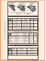
Description of RSC-2 controller outputs
Antenna
Control outputs:
No 30: channel 1
No 87: channel 2.
Power inputs :
No 85: battery (+) 12V/DC or 24V/DC.
No 86: battery minus (ground).
Antenna: (do not cut !)
The wire antenna should be left free lying or
hanging, dependent on the fitting conditions.
Do not connect or group with other wires. It
has a direct influence on the functioning of
the key fob transmitter.
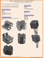
RSC-2 viewed from
the output side
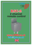
RSC-2 external design
Figure 1
Figure 2
This is a copy "Operating Manual " of the paper
Fitting the RSC-2 controller
Before starting to fit the controller, it is recommended to pay special
attention to the proper connection of its power outputs.
(+)
13
1 channel
30
86 (-)
85
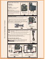
Connect the power supply to the controller using female
connectors inserted onto the output leads. Solder the
female connector or tighten the clamps on the wires of the
controlled device. It is recommended to follow the connection
pattern closely to avoid damaging the controller.
87
2 channel
12V (+)
(-)
RSC-2 outputs
(connection side view)
Figure 4
Female connector
Figure 3
14
Power support for RSC-2 controllers (Fig.5) can be used for
connecting.
You must NOT solder the wires to the output leads. Soldering
wires can cause controller damage and loss of warranty.
RSC-2 controllers have, by standards, male output connector leads, which
are powered with 12V/DC or 24V/DC power supply.
An example connection diagram is shown on Fig 6 and 7.
Power support for RSC-2 controllers
Description of the output leads of the support:
Red: 0.75mm (coupled wire): +12V/DC or 24V/DC power supply
Black with a red strap: 0.75mm (coupled wire): negative power supply.
Bulb or relay
1 channel (24V)
Bulb or relay
2 channel(24V)
Two loose black wires, 1.5mm: outputs for channels 1 and 2.
RSC-2 Power support
Figure 5
15
30
(+)
86 (-)
85
(+)
(-)
87
Bulb 1
(12 V)
24V (+)
16
(-)
12V
(+)
(-)
Bulb 2
(12 V)
1 channel - Bulb 1
2 channel - Bulb 2
12V (+)
Example connection diagram:
RSC-2 for controlling 24V bulbs
Example connection diagram:
RSC-2 for controlling 12V bulbs
Figure 6
Figure 7
Operating Manual RSC-2 LPRS (version for web exclusively)11-02-2010R
11
(-)
www.LPRS.co.uk Email. [email protected]