1
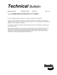
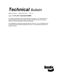
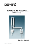
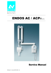
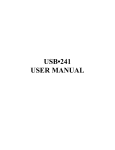
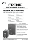
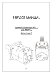
SERVICE MANUAL
Hydraulic Motors type MS(Y)…
and MLHS(Y)…
2008
-2-
Service Manual
Hydraulic Motor type MS(Y)…
MLHS(Y)…
Disassembly
Castellated
Nut
Washer
Castellated
Nut
Dust
Seal
Housing
Parallel
Key
Plug
Shaft and Bearing
kit
“O”- Ring+
69x3
Shaft
Seal
Valve
Drive II
Seal
Intermediate
Plate
“O”- Ring
83x2
“O”- Ring
83x2
Channel
Plate
Cardan
Shaft
Seal
Ring
“O”- Ring
83x2
Roll-Gerotor
Set
Valve
Plate
Balance
Plate
“O”- Ring
45x2
“O”- Ring
24x2 Spring
Washer
Spacer
Pin
End
Cover
Plug
Screw
“O”- Ring
with Tacho connection
Name
Plate
Rivet
Housing ”A”
Housing ”Q”
Housing ”E”
Housing ”W”
-3-
Housing”F”
Housing”B”
Service Manual
Hydraulic Motor type MS(Y)S(V,U)…
MLHS(Y)S(V,Z,U)…
Disassembly
Safety
cap
“O”- Ring
75x3
MSU
MLHSU
Seal
Ring
Flange
“O”- Ring
83x2
Screws
Cardan
Shaft
Roll-Gerotor
Set
Safety
cap
“O”- Ring
85x2
MSV
MLHSV
Valve
Drive
“O”- Ring
83x2
Seal
Ring
Channel
Plate
Flange
“O”- Ring
83x2
Cardan
Shaft
Screws
Safety
cap
MLHSZ
Screws
Ball
Roll-Gerotor
Set
Valve
Drive
“O”- Ring
102x3
Flange
Plug
“O”- Ring
83x2
Seal
Channel
Plate
“O”- Ring
83x2
Cardan
Shaft
Seal
Ring
Safety
cap
“O”- Ring
100x3(MSS)
102x3(MLHSS)
MSS
MLHSS
Roll-Gerotor
Set
Ball
Valve
Drive
“O”- Ring
83x2
Plug
Flange
Seal
Channel
Plate
“O”- Ring
83x2
Cardan
Shaft
Seal
Ring
Roll-Gerotor
Set
Valve
Drive “O”- Ring
83x2
“O”- Ring
83x2
Valve
Plate
Ball
Channel
Plate
Balance
Plate
“O”- Ring
45x2
Spring
Washer
Spacer
Pin
Plug
“O”- Ring
24x2
Ball
End
Cover
Screw
“O”- Ring
Name
Plate
Rivet
-4-
Service Manual
Hydraulic Motor type MS(Y)…
MLHS(Y)…
Disassembly
The instructions in this manual concern motor
types MS and MLHS.
Cleanliness is extremely important when
repairing these motors. Work on clean surface!
Before disassembly, drain the oil from the
motor and dry the working bench.
If there is castellated nut, washer or key, they
have to be removed from the shaft.
Although not all drawings show the motor in
disassembly devise (vice with soft clamping
jaws), we recommend the motor to be tightened
during disassembly.
6. Separate Channel Plate from Roll-gerotor
set.
7. Remove O-ring 83x2 (2 pcs.), and balls (2
pcs.) from the Channel Plate grooves.
8. Remove the roll-gerotor set carefully to
prevent dropping of rollers and rotor from stator.
Do not dismount!
“O”-Ring
Cardan
Shaft
1. Unscrew the Drain plug with S6 Allen key
and remove the washer (O-ring for MLHS).
Roll-Gerotor
Set
2. Place the motor in disassembly devise with
output shaft down.
Drain
Plug
Washer
(O-Ring for SAE)
Fig.3
9. Remove cardan shaft from the splines of
output shaft (see Fig.3).
End Cover
10. Separate Intermediate Plate from housing.
Screw
11. Remove O-ring 83x2 and Seal Ring from
the Intermediate Plate.
12. Fix Housing in a hydraulic press and push
output shaft with bearing kit out of housing (see
Fig.4).
Note: Replace Output Shaft and bearing kit
as a unit. If not necessary do dismount the
bearing kit!
Fig.1
3. Unscrew screws using a S17 torque
wrench. (see Figure 1)
4. Remove end cover assembly.
5. Separate Valve Plate from Channel Plate
and remove Valve Drive (see Fig.2).
Channel
Plate
Ball
Valve
Drive
Valve
Plate
“O”- Ring
“O”- Ring
Fig.4
Fig.2
-5-
Service Manual
Hydraulic Motor type MS(Y)S(V,U)…
MLHS(Y)S(V,Z,U)…
Disassembly
SK 41 5134 0449 for MLHSY…D
SK 41 5134 0452 for MLHSY…7…D
SK 41 5134 0000 for MLHSY…U…D
SK 41 5134 0005 for MLHSY…7U…D
SK 41 5123 8820 for MLHSYS…B
SK 41 5123 8835 for MLHSYS…7…B
SK 41 5123 8800 for MLHSYV…B
SK 41 5123 8815 for MLHSYV…7…B
13. Remove dust seal, shaft seal and O-ring
carefully from the Housing.
End Cover Disassembly:
Balance
Plate
“O”-Ring
“O”-Ring
1. CLEANING:
Wash all parts (except seals) in a weak
End cover
solvent on carbon base and then degreased.
Pin
2. MEASURING AND REPLACEMENT:
Measure all parts and compare their actual
Spring
dimensions with the nominal ones given in the
Washer
technical documentation. Replace any parts
with scratches or burrs that could cause leakage
or damage with new ones. Use new seals and
washers when reassembling the motor.
Fig.5
3. LUBRICATION:
Lubricate all frictioning parts, which should
14. Turn the end cover with the hole
be reassembled with light film of petroleum
conversely on a clean soft surface. Knock several
jelly.
times using a plastic hammer on the rear side. Set
in order the fallen parts apart (see Fig.5).
Spacer
15. Remove “O”-Rings (2 paces.) from the
grooves of the balance plate.
16. Remove the pin using a vice with soft
jaws or pliers knocking on the balance plate and
swivelling it round the pin simultaneously.
Seal Kits:
SK 41 5127 9047 for MS…- series 4
SK 41 5127 8200 for MS…U…- series 4
SK 41 5129 9400 for MSS… - series 3
SK 41 5129 1488 for MSV… - series 3
SK 41 5129 2732 for MSU…
SK 41 5127 4200 for MSY… - series 3
SK 41 5127 4000 for MSY…U… - series 3
SK 41 5129 0400 for MSYS… - series 2
SK 41 5129 0410 for MSYV… - series 2
SK 41 5132 5148 for MLHS…D
SK 41 5132 5153 for MLHS…7…D
SK 41 5132 0000 for MLHS…U…D
SK 41 5132 0005 for MLHS…7U…D
SK 41 5123 9370 for MLHSS…C
SK 41 5123 9375 for MLHSS…7…C
SK 41 5123 9434 for MLHSZ…C
SK 41 5123 9439 for MLHSZ…7…C
SK 41 5124 6220 for MLHSV…C
SK 41 5124 6225 for MLHSV…7…C
-6-
Service Manual
Place bearing housing on clean soft surface.
Lubricate shaft seal and dust seal with light film
of clean petroleum jelly.
1. Place shaft seal in the bearing housing
and firmly push with Seal driver (see Fig.6).
2. Install dust seal in the bearing housing.
Carefully press dust seal into place.
Lips of shaft seal and dust seal must face
outward.
PRESS
Shaft Seal
Hydraulic Motor type MS(Y)…
MLHS(Y)…
Reassembly
O.D.>45
Seal
Driver
Rotate the shaft by hand. Max. moment of
rotation of the shaft with assembled bearing is
0,25 daNm.
Alignment studs can be very helpful in
reassembly of the motor. Install two studs
М10x200 diagonally in the housing.
5. Lubricate and install the O-ring 69x3 in
housing seal grooves.
6. Install the seal ring in the Intermediate plate
and assemble it through the studs. Lubricate Oring 83x2 and place it in seal groove of
Intermediate Plate.
7. Install the cardan shaft into splines of the
output shaft.
Timing Procedure
Dust Seal
O.D.<35
Housing
Fig.6
Important: After installing in bearing
housing check seal condition. If damaged, cut or
improperly installed, replace with new ones.
8. Orientate the Roll-Gerotor set acc.to Fig.8
and assemble the rotor splines into the cardan
shaft splines. (If necessary, turn the shaft to one or
another direction for keeping symmetry of rotor
towards stator.)
3. Place the housing in reassembly device
(vice). Lubricate all inner surfaces.
Mark
Fig.8
9. Install the valve drive into the rotor spline
sector.
10. Mark the rotor at the point where the tip of
a spline tooth is opposite to the bottom of a tooth
in the external rotor teeth as shown on Fig.8 and
9.
Fig.7
4. Use a press to install output shaft with
bearing kit into housing (see Fig.7). Be careful
not to invert or damage the seals.
11. Mark the bottom of a spline on the valve
drive. Line up mark on rotor and valve drive.
12. Lubricate O-rings 83x2 (2 pcs.) and place
them in seal grooves of both sides of Channel
Plate.
-7-
Service Manual
Hydraulic Motor type MS(Y)…
MLHS(Y)…
Reassembly
Reverse rotation is obtained by rotation of the
Valve Plate counter clockwise (as shown on
Fig.9b) until splines in the two parts engage.
Valve
Plate
0
CW
15 C
Valve
Drive
Reassembly of End Cover:
Timing
Mark
16. Mount the lubricated “O”-Rings (2 pcs.) in
the relevant grooves of the balance plate (see
Fig.5).
Bottom
of tooth
Roll-gerotor
Set
17. Stave the preliminarily lubricated pin into
the balance plate hole (to the thin end).
B
A
B
CCW
Fig.9a
A
18. Place the cover with the front for
nameplate downwards. Lubricate lightly all
internal cap surfaces to protect seals. Put the
spring washer into hole with passing diameter.
19. Place the balance plate (set) inside the end
cover with the pin orientated to fall in with the
hole of its bottom. Use a plastic hammer.
Lubricate spacer and install in the balance
plate hole.
Parts are correctly assembled when at pressing
the front surface of balance plate by thumbs
downwards, the balance plate jumps up itself as a
result of spring force.
CW
13. Lubricate the roll-gerotor set surface and
place on it the channel plate.
14. Lubricate and install 2 psc. Balls in
channel plate ball grooves (see Fig.2).
15. Align mark on valve drive with a hole in
the outer rim of the Valve Plate. Turn Valve
Plate clockwise (as shown on Fig.9a) until
splines in the two parts engage / rotation about
15°/.
20. Mount the end cover (set) carefully over
both studs. Make sure that the port face of end
cover coincides with the orientated drain port.
Reverse Rotation:
21. Install the screws in End cover. Tighten
screws with 6÷7 daNm torque using an S=17 mm
torque wrench.
Valve
Plate
Valve
Drive
150CW
22. Install washer (O-ring for SAE) on drain
plug. Tighten plug with Allen key S6 with torque
2,0 ÷ 2,5 daNm.
Key
Timing
Mark
Bottom
of tooth
Roll-gerotor
Set
Castellated
Nut
Washer
Key
B
A
CW
B
A
CCW
Fig.9b
Fig.10
-8-
Service Manual
Hydraulic Motor type MS(Y)…
MLHS(Y)…
Reassembly
23. Install key in shaft key groove. For cone
shafts install washer and screw castellated nut
(see Fig.10).
Disassembly and reassembly of short (without bearings) motors type “S”, “V”, “Z”and “U”:
These motors are the same as the standard motors without bearing unit /Output shaft and Housing/.
Intermediate plate is replaced with Flange. Follow the same disassembly and reassembly procedures as
for the rear section of standard motor.
For MSS (MLHSS, Z) only: Fit shaft cap for MSS motors to flange. Place the flange in the fixture
with the cap downwards. Screw 2 assembly studs M12 in opposite flange holes by hand. Install in
flange cardan shaft. Shaft cup will prevent dropping out of cardan shaft. Follow the reassembly
procedures from 8 to 21. Mount the rear section carefully over asembly studs. Turn motors with the
flange upwards and remove the shaft cap. Lubricate cone seal ring and place it in the flange. Lubricate
O-ring and install into flange seal groove.
For MSV (MLHSV) only: Fit shaft cap for MSV motors to Roll-gerotor set. Screw 2 assembly
studs M12 in opposite Roll-gerotor set holes by hand. Install cardan shaft in Roll-gerotor set. Shaft
cup will prevent dropping out of cardan shaft. Follow the reassembly procedures from 8 to 20. Mount
the rear section carefully over both studs. Replace studs with screws. Turn the motor on 180 o and
remove shaft cap. Mount roll-gerotor set to end cover with two screws M5 using S5 (4) Allen head
spanner. Tighten with 0,5÷0,7 daNm torque. Install flange to roll-gerotor set and tighten with two
screws М5х16 with 0,5÷0,7 daNm torque. Lubricate cone seal ring and place it in front cup. Lubricate
O-ring and install into front cap seal groove.
-9-