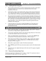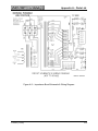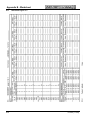
1
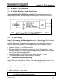
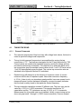
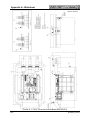
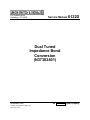
645 Russell Street
Batesburg, SC 29006
Service Manual 6122D
Dual Tuned
Impedance Bond
Conversion
(N37302401)
November, 2000
© 2000, Union Switch & Signal Inc.
Printed in U.S.A.
An ANSALDO Signal Company
Revision History
This service manual supersedes all previously issued. Please destroy all previously
issued manuals.
Original Publication
6122D (11/00)
11/00
i
Table of Contents
Section
Topic
Page
1
GENERAL INFORMATION ...............................................................1-1
1.1
1.2
1.3
Introduction ........................................................................................1-1
R.A.I.L. Team and Technical Support................................................1-1
Suitable Locations to Convert Bonds.................................................1-1
2
TEST EQUIPMENT ...........................................................................2-1
2.1
2.1.1
2.1.2
2.1.3
2.1.4
2.1.5
2.1.6
2.1.7
Required Test Equipment ..................................................................2-1
AC Voltage Breakdown Tester (Hipot Tester)....................................2-1
AC Power Supply...............................................................................2-1
Transformer, Impedance Matching ....................................................2-1
AC Ammeter(s) ..................................................................................2-2
AC Voltmeters....................................................................................2-2
Oscilloscope ......................................................................................2-2
Worksheet .........................................................................................2-2
3
CONVERSION/INSTALLATION .......................................................3-1
3.1
3.2
3.3
3.3.1
3.3.2
3.3.3
3.3.4
3.3.5
3.3.6
Impedance Bond Oil ..........................................................................3-1
Parts Dropped inside the Bond. .........................................................3-1
Bond Conversion Process .................................................................3-3
Removing the Bond Cover.................................................................3-3
Removing the Existing Tuning Unit....................................................3-3
Untuned Bond Tests ..........................................................................3-4
Installing the New Tuning Unit. ..........................................................3-7
Dielectric Breakdown (Hipot) Test .....................................................3-7
Data Sheet Sign-Off...........................................................................3-8
4
TUNING/ADJUSTMENT....................................................................4-1
4.1
4.1.1
4.1.2
4.1.3
4.2
4.2.1
4.2.2
4.2.3
4.2.4
Tuning the Bond. ...............................................................................4-1
General Comments............................................................................4-1
Tuning Procedure ..............................................................................4-3
Trial #1...............................................................................................4-5
Impedance Adjustment of the Bond...................................................4-7
General..............................................................................................4-7
Impedance Adjustment at 1 volt, 91.67 hertz.....................................4-8
Impedance Adjustment at 1 volt, 250 hertz........................................4-8
Trial #2...............................................................................................4-9
6122D (11/00)
i
Table of Contents
5
CONVERSION COMPLETION..........................................................5-1
5.1
5.2
5.2.1
5.2.2
5.3
5.4
Replacing the Bond Cover.................................................................5-1
Final Electrical Checks ......................................................................5-1
Breakdown Test.................................................................................5-1
Impedance Checks ............................................................................5-1
Replacing the Nameplate. .................................................................5-2
Final Data Sheet Sign – Off ...............................................................5-3
APPENDIX A
PARTS LIST..................................................................................... A-1
APPENDIX B
WORKSHEET .................................................................................. B-1
List of Figures
2-1
3-1
3-2
3-3
3-4
4-1
4-2
5-1
A-1
A-2
Alternate Equipment, AC Power Supply ............................................2-1
Component Identification ...................................................................3-2
Breakdown Tests between Coils........................................................3-4
Breakdown Tests between Two Coils and Case................................3-5
Impedance Check/Tuning Test Circuit...............................................3-6
Simplified Circuit Schematic ..............................................................4-1
Tuned Bond Schematic .....................................................................4-4
Generalized Graph, Impedance versus Frequency ...........................5-2
Dual Tuned Impedance Bond (N37302401) ..................................... A-2
Impedance Bond Schematic & Wiring Diagram ................................ A-3
List of Tables
3-1
4-1
5-1
ii
Untuned Impedance Check ...............................................................3-6
Wire Connections ..............................................................................4-3
Tuned Impedance Check...................................................................5-2
6122D (11/00)
Section 1 - General Information
1.1
INTRODUCTION
This manual provides instructions to convert impedance bonds N451003-2601 or -2602
into impedance bond N37302401. Impedance bond N451003-2601 is tuned to a single
frequency of 100 hertz, while impedance bond N451003-2602 is tuned to a single
frequency of 91.67 hertz. Impedance Bond N37302401 is simultaneously tuned to two
frequencies, 91.67 and 250 hertz.
All three of these bonds use the basic untuned bond, N451662-3403. Desired tuning
and impedance (tuned) is obtained by connecting the appropriate tuning unit to the
untuned bond, tuning the bond, and then adjusting the bond for proper impedance. The
tuning process and the impedance adjustment are necessary to compensate for
variation (tolerances) in various tuning component values.
Conversion Kit X37300001 supplies a complete preassembled tuning unit (N37302501),
a nameplate (M437818) with assigned serial number for the converted bond, and four
drive screws (00760139) for attaching the nameplate.
1.2
R.A.I.L. TEAM AND TECHNICAL SUPPORT
The Rapid Action Information Link (R.A.I.L.) Team is comprised
of experienced product and application engineers ready to assist
and resolve technical issues concerning any US&S product.
Any questions regarding the contents of this Service Manual can
be answered by contacting the R.A.I.L. Team via e-mail at
[email protected] or a toll-free call to 800-652-7276.
1.3
SUITABLE LOCATIONS TO CONVERT BONDS
Union Switch & Signal Inc. recommends against converting a bond in the field. While it
is possible in theory to convert a bond in the field if certain precautions are taken, there
are many practical deterrents to field tuning.
Under ideal circumstances, the bond should be pulled from its track circuit and taken to
a shop or laboratory environment. The location needs to provide electrical power for
testing equipment. An overhead crane system is desirable. A bond weighs between 900
and 1000 pounds. Because it is necessary to remove the cover, the location should
provide shelter against inclement weather and debris.
Tuning component values were chosen based on their room temperature values; hence,
bond tuning and impedance adjustment is best done near room temperature (60 to 80
degrees Fahrenheit), but ambient temperature is not critical. Extreme temperatures will
have a noticeable effect on tuning components, consequently tuning and impedance
adjustment should not be done in extreme temperatures.
6122D (11/00)
1-1
Section 1 – General Information
This page is intentionally blank.
1-2
6122D (11/00)
Section 2 – Test Equipment
2.1
REQUIRED TEST EQUIPMENT
2.1.1 AC Voltage Breakdown Tester (Hipot Tester)
Tester with 3000 volt R.M.S. 60-hertz capability. Must either display measured
leakage current value or have trip indicators indicating when one and also two milliamperes of leakage current is exceeded.
FIGURE 2-1 ALTERNATE EQUIPMENT - AC POWER SUPPLY
2.1.2
AC Power Supply
Output -- AC sinewave, 200 VA, adjustable over 0- to 60-volt range. Must be able to
provide 91.67 hertz & 250 hertz with 0.1 hertz resolution, although 100 hertz is
desirable. Alternatively, Separate power supplies may be used for each frequency or
the power supply may consist of the following equipment as illustrated in Figure 2-1.
a) Frequency Counter: 10- to 5000-hertz range.
b) Sine Wave Oscillator(s): Capable of providing 91.67 and 250 hertz with 0.1 hertz
resolution, although 100 hertz is desirable. Equipped with a variable output voltage;
vernier (fine) adjustments are desirable
c) Amplifier: Capable of 0 to 5000 hertz, output ohms within 4 to 16 ohms
(16 preferred), and minimum output capacity of 200 Watts.
2.1.3
Transformer, Impedance Matching
Rated 360 VA min. at 60 volts AC, 60 hertz. Low voltage winding rated 6 volts AC min.
at 60 hertz and rated for 20 amperes continuous current. Suggested (approximate)
turns ratio for various power supply output impedances are:
a) 16-Ohm output, 10-to-1 (step down)
b) 8-Ohm output, 7-to-1 (step down)
c) 4-Ohm output, 5-to-1 (step down)
NOTE:
US&S transformers PP-10 (P/N: 98825011) and W-400 (P/N: N451428-01XX)
are suitable for 16-ohm output impedance.
6122D (11/00)
2-1
Section 2 – Test Equipment
2.1.4
AC Ammeter(s)
AC Ammeter(s) rated for 50 to 300 hertz; current ranges -- 0 to 1.5 and 0 to 10
amperes.
2.1.5
AC Voltmeters
AC Voltmeters rated for 50 to 300 hertz, 1 megaohm minimum input impedance; voltage
ranges -- 0 to 2 and 0 to 10 volts.
2.1.6
Oscilloscope
Oscilloscope rated for 0.1 megahertz minimum, 1 megaohm minimum input impedance;
voltage ranges: 0 – 2 and 0 - 10 volts AC.
2.1.7
Worksheet
The test worksheet (two pages) are provided in Appendix B of this service manual.
2-2
6122D (11/00)
Section 3 – Conversion/Installation
3.1
IMPEDANCE BOND OIL
The bond contains slightly conductive, electrical grade oil (often referred to as
transformer oil) to promote cooling and to improve the transfer of unwanted heat to the
bond’s case for dissipation into the bond’s environment. Since a very large portion of
the bond is immersed in the oil, the oil provides an unwanted path for the flow of electric
current. The oil acts like a resistor placed in parallel with the electrical components of
the bond. Impedance bonds are low impedance devices. Fortunately for quality
transformer oil, the effective parallel resistance is much higher than the impedance of
the bond and its tuning circuit. Quality transformer oil produces a negligible effect on the
tuning and impedance of the bond. The oil does have a noticeable and significant effect
when performing a dielectric breakdown (Hipot) test.
WARNING:
THE TRANSFORMER OIL IS A PETROLEUM PRODUCT AND, AS SUCH, IS
COMBUSTIBLE. To avoid risk of personal injury, DO NOT EXPOSE IT TO FLAMES
OR TO SPARKS. USE ADEQUATE VENTILATION TO AVOID A BUILD-UP OF
FUMES.
Transformer oil deteriorates over time, especially at elevated temperatures and/or high
voltage stress. Dirty and/or deteriorated oil is more conductive and may also be more
corrosive. The more conductive the oil becomes, the more effect it will have on the
bond’s electrical properties.
Bond conversion requires removing the cover. Inspect the oil before installing the new
or converted tuning unit. If the transformer oil is of adequate quality then proceed with
the conversion with the oil in the bond. If the oil is dirty or obviously deteriorated, then
remove the dirty oil before proceeding with the conversion. Replace the oil after the
bond has been converted, tuned, and adjusted to proper impedance. The oil should be
filled to the bottom of the square notch on the side of the case.
CAUTION
METALLIC PARTS DROPPED INTO THE BOND MUST BE REMOVED. Failure to do
so may result in property damage.
3.2
PARTS DROPPED INSIDE THE BOND
Avoid dropping metallic parts (screws, nuts, washers, etc.) into the bond, especially
small metallic parts. Small objects that are dropped into the bond are difficult to find and
retrieve. Metallic objects can easily short propulsion winding turns. An object dropped to
the bottom initially may not cause any problem; but under heavy vibration conditions, it
may eventually find its way to the propulsion coil. Under fault conditions it may facilitate
formation of a welded metallic bridge between propulsion turns.
6122D (11/00)
3-1
Section 3 – Conversion/Installation
FIGURE 3-1 - COMPONENT IDENTIFICATION
3-2
6122D (11/00)
Section 3 – Conversion/Installation
WARNING
POSSIBLE HIGH VOLTAGE ASSOCIATED WITH ELECTRONIC TESTING.
DISCONNECT POWER SOURCE BEFORE MAKING ANY ADJUSTMENT OR
CONVERSION PROCEDURE. FAILURE TO COMPLY MAY RESULT IN EQUIPMENT
DAMAGE, PERSONAL INJURY OR DEATH.
ONLY QUALIFIED PERSONNEL SHOULD ATTEMPT PROCEDURES OUTLINED
WITHIN THIS SERVICE MANUAL.
3.3
BOND CONVERSION PROCESS
3.3.1
Removing the Bond Cover
The cover is secured to the case at the four upper corners of the case with one
5/8”-11 x 3” - “T” slotted head bolt on the underside of the cover at each corner. The
other end of each bolt is secured with a 5/8” flat washer, a 5/8” split-lock washer and a
5/8”-11 hex nut. (Reference Figure A-1, Items 17, 18, 19 and 20.)
1.
Using a 5/8” wrench, loosen and remove the four sets of nuts, washers and bolts.
2.
Lift the cover off the case, being careful not to slide the cover across the case.
The case and bond are sealed by forming a gasket with material packed into a
groove. Sliding the cover across the case may damage the gasket. Lift the cover
high enough so that all overhangs and ridges adequately clear the rest of the
bond when the cover is moved away.
3.3.2
Removing the Existing Tuning Unit
CAUTION
Metallic parts dropped into the bond must be removed. Failure to do so may
result in property damage for the reasons outlined in section 3.2.
1.
Refer to Figure 3-1. Locate terminal block “TB4” (6-way, AREMA-style terminal
block).
2.
Loosen and remove the top two nuts and remove the top washers from terminals
1, 2 and 3. (Reference Figure A-1, Views A & B.)
3.
Remove leads 1 (red), 2 (green), and 3 (black) from terminals 1, 2 and 3. These
leads originate from the secondary (tuning) coil located on top of bond’s
propulsion (track) winding. They pass through the vertical grommet at the back of
the tuning unit.
NOTE:
When lead 1 or 3 is removed, the bond is no longer tuned.
6122D (11/00)
3-3
Section 3 – Conversion/Installation
4.
Also remove any remaining loose washers.
5.
Feed the three leads one-at-a-time back through the grommet.
6.
The tuning unit is secured to the four threaded rods that pass through the ends of
the cast iron clamping bars, located on the top of the bond’s core stack. There is
a ½” flat washers, a ½” split-lock washer, and a ½”-13 hex nut securing the
tuning unit at each rod. Loosen the four nuts with a wrench and then remove the
washers and nuts. (Reference Appendix A, Figure A-1, Items 17, 18, 19 and 20.)
7.
Lift the tuning unit straight up until clear of the rods.
8.
Observe and note the number of flat washers on the rods directly under the
tuning unit. These washers serve to properly space the tuning unit above the
core stack. The same number of washers must be in place when reinstalling the
tuning unit.
3.3.3
UNTUNED BOND TESTS
It is prudent to assure the untuned bond impedance is within its expected range before
assembling a new or converted tuning unit into the bond. A dielectric breakdown (Hipot)
test may be done at this time. It must be done after installing the new tuning unit.
WARNING:
POSSIBLE HIGH VOLTAGE ACROSS SECONDARY COIL LEADS. REMOVE
POWER AND WAIT TEN SECONDS BEFORE CONNECTING OR DISCONNECTING
ANY TERMINALS TO AVOID PERSONAL INJURY OR DEATH.
FIGURE 3-2 - BREAKDOWN TEST BETWEEN COILS
3-4
6122D (11/00)
Section 3 – Conversion/Installation
FIGURE 3-3 – BREAKDOWN TEST BETWEEN TWO COILS (CONNECTED) AND CASE
3.3.3.1
Voltage Breakdown Test (Hipot)
Apply 2000 volts, 60 hertz, for one minute between the following:
1. Propulsion coil and secondary (tuning) coil.
2. Propulsion coil and a core bolt.
3. Secondary coil and a core bolt.
See Figures 3-2 and 3-3 for illustration. Tests 2 & 3 may be done at the same time by
connecting the two coils together with a jumper. (If a failure occurs, then conduct Tests
2 and 3 separately.) No arc-overs are permitted. A maximum leakage current of 1 milliampere is permitted for a bond without transformer oil. A maximum leakage current of
2 milli-ampere is permitted for a bond with transformer oil. For each part, circle on the
worksheet the appropriate test result, pass or fail.
6122D (11/00)
3-5
Section 3 – Conversion/Installation
FIGURE 3-4 IMPEDANCE CHECK/TUNING TEST CIRCUIT
3.3.3.2
Impedance Check
WARNING:
Possible HIGH VOLTAGE across secondary coil leads. Remove power and wait
ten seconds before connecting or disconnecting any terminals to avoid possible
personal injury or death.
Set up the circuit of Figure 3-4. Adjust the AC power supply to 60, 91.67 or 100 hertz.
Adjust the AC power supply output voltage until 1 volt ± 0.01 volt is measured across
bond terminals “A” and “B”. Measure and record on the worksheet the frequency,
voltage and the current. The current indicated by the ammeter must be within the range
tabulated below for the appropriate frequency. On the worksheet, circle the appropriate
result, pass or fail. If the bond fails the test, then the air gap needs adjusting.
Test Conditions
Voltage, Volts
Freq., Hz.
60
1.00
91.67
1.00
100
1.00
Current (Amps
Min.
Nom.
5.39
5.68
3.305
3.644
3.03
3.34
Max.
5.96
3.982
3.65
TABLE 3-1 - UNTUNED IMPEDANCE CHECK
NOTE: A suitable variable transformer (Variac) may be used as the AC power supply at
60 Hz.
3-6
6122D (11/00)
Section 3 – Conversion/Installation
3.3.4
Installing the New Tuning Unit
1.
This procedure assumes the core stack is already secured in place. Verify that it
is already secured. If not, secure the core stack and check the untuned
impedance of the bond.
2.
Verify that the number of flat washers (5/8”) observed and noted per Subsection
3.3.2, step 8 are still in place. If not, then add washers as required to obtain the
same number (hence the same spacing as before implementing this procedure).
3.
The autotransformer assembly is located at the back underside of the tuning unit.
Position the back end of the tuning unit near the back end of the bond. The front
end of the bond has the thick heavy copper terminals. There are three lead wires
(#1 red, #2 green, and #3 black) exiting the bond’s secondary (tuning) coil. Feed
these three wires, one at a time, through the tuning unit’s grommet from the
underside of the tuning unit.
4.
Lower the tuning unit over the four vertical threaded rods. The tuning unit is
oriented with the autotransformer at the back end of the bond and with the
terminal blocks on top.
NOTE: Steps 5 and 6 can be postponed until just before assembly of the bond’s cover.
5.
Place one 5/8” flat washer, one 5/8” split lock washer, and one 5/8”-11 hex nut
over each rod. Using a wrench, tighten all four nuts.
6.
“Prick punch” the threads of all four rods at the top edge of the nuts. This is done
to ensure that vibration does not loosen the nuts.
7.
Place one copper washer over terminal posts 1, 2, and 3 on the AREMA-style
terminal block. This terminal block is denoted as “TB4” in Figure 3-1.
8.
Place the bond’s secondary (tuning) coil leads 1 (red), 2 (green) and 3 (black)
over terminal posts 1, 2, and 3, respectively, on AREMA-style terminal block
denoted as “TB4” in Figure 3-1.
9.
Add another copper washer to each of the three terminal posts.
10.
Add 2 AREMA-style #14-24 brass nuts (acorn-style) to each of the three terminal
posts.
11.
Tighten the two nuts: tighten the lower nut first, then “jam” the upper nut against
the lower nut.
3.3.5
Dielectric Breakdown (Hipot) Tests
Perform the tests listed in Subsection 3.3.3.1 steps 1, 2 and 3. For each test, circle on
the worksheet the appropriate test result, pass or fail.
6122D (11/00)
3-7
Section 3 – Conversion/Installation
3.3.6
Data Sheet Sign-Off
Tester should initial and date the data sheet, refer to Appendix Section B.1.3.
3-8
6122D (11/00)
Section 4 – Tuning/Adjustment
FIGURE 4-1 - SIMPLIFIED CIRCUIT SCHEMATIC
4.1
4.1.1
TUNING THE BOND
General Comments
a.
The resonant frequencies of this bond vary with voltage level; hence, the bond is
tuned at specified voltages and frequencies.
b.
Tuning for both resonant frequencies is accomplished by varying the tap
connections of “T2”. Tap leads are terminated on the 10-way terminal strip, TB3.
Current values are measured at specified frequency and bond voltage and are
recorded at various tap connections. The objective is to determine which set of
tap connections gives the smallest current value at both 1 volt 91.67 hertz and at
1 volt 250 hertz applied across the bond. The various tap connection sets are
tabulated in the Appendix Section B.5 worksheet.
c.
Desired tuning will always be in the direction of minimum current. A current
minimum will also be an impedance peak. Near either resonance frequency
(± 10 Hz.), there is only one impedance peak possible, hence an upward turn in
measured current (current decrease followed by a current increase) indicates
that the bond is nearly tuned to that particular desired frequency.
d.
The tap connection tabulation contains 25 different sets. The turns ratio can be
varied by ± 12.5% in 1.043% increments. This permits the effective “C1”
capacitance and the “T2” inductance can vary ± 23.5% in 2.1% increments.
Measurement for all possible sets is not intended. Initially, coarse tuning can be
done using tap leads 1 through 5 (1.052% turns increments). Once an upward
6122D (11/00)
4-1
Section 4 – Tuning/Adjustment
turn in current has been established, fine turn increments can be used to search
for the current minimum using tap leads 6 through 10 (1.043% turns increments).
e.
Minimum “T2” turns occur at terminals TB3-5 & TB3-6 (the innermost terminals).
Maximum turns occur at terminals TB3-1 & TB3-10 (the outermost terminals).
Maximum “T2” inductance (L2) occurs at maximum turns. Maximum effective
“C1” occurs at maximum turn ratio (not necessarily maximum turns), where turn
ratio equals number of turns connected to C1 divided by the turns for “L2”.
f.
Tuning is done prior to assembly of the bond cover.
g.
The -x denotes the terminal number (x = 1, 2, 3, etc.)
TB4-x
AREMA-style, 6-way terminal block
TB3-x
10-way barrier terminal strip
TB1, TB2,
TB5, TB6
3-way barrier terminal strips located on the resistor printed circuit
boards
h.
The impedance value of the bond can be adjusted by changing connections on
TB1, TB2, TB5, & TB6 on the resistor printed circuit boards. Maximum
impedance occurs when the connections for minimum adjusting resistance are
chosen; which are TB1-2 & TB2-2 and TB5-2 & TB6-2 terminals.
i.
Changing the inductance of “T2” affects the tuning of both resonant frequencies,
but the tuning at 91.67 hertz is affected more (% change) than the tuning at 250
hertz. Changing the turns ratio of “T2” (thereby changing effective value of “C1”)
affects the tuning at 250 hertz more than the tuning at 91.67 hertz. The tuning
procedure repeats two basic processes. First, adjust the inductance to achieve
91.67 hertz tuning. There are two red leads designated for this purpose. Second,
adjust the turn ratio to achieve the 250 hertz tuning. There are two white leads
designated for this purpose. Repeat these two processes until no changes in
connections are required.
4-2
6122D (11/00)
Section 4 – Tuning/Adjustment
4.1.2
Tuning Procedure
WARNING:
Possible HIGH VOLTAGE across secondary coil leads. Remove power and wait
ten seconds before connecting or disconnecting any terminals to avoid possible
personal injury or death.
a.
Connections to “TB3” for leads “A”, “B”, “Y”, and “Z” will be varied during the
tuning procedure. Connections to “TB1”, “TB2”, “TB5”, and “TB6” for leads “C”,
“D”, “W”, and “X” respectively, will be varied during the impedance adjustment
procedure. The tuning unit’s initial lead connections to “TB1”, “TB2”, “TB3”,
“TB5”, and “TB6” were chosen to ensure that the leads have sufficient length to
reach all terminals. The initial wiring connections (per wiring diagram Figure 4-2)
do not represent nominal values. “Initial wiring,” “nominal,” “minimum turns” and
“maximum turns” connections are listed below.
Tuning can be accomplished by starting with any set of connections given in the
tuning table and the impedance adjustment table (see Appendix Section B.5
worksheet), but it is usually best to start at connections for either minimum or
maximum turns. This tuning procedure will assume starting with “maximum
turns”. Rewire the tuning unit for the “maximum turns” connections.
TABLE 4-1 – W IRE CONNECTIONS
Wiring
Initial
Nominal Tuning
Maximum Turns
Minimum Turns
“A” & “Y”
TB3-5
TB3-3
TB3-1
TB3-5
“B” & “Z”
TB3-10
TB3-8
TB3-10
TB3-6
Leads
“C”
TB1-1
TB1-1
TB1-1
TB1-1
“D”
TB2-1
TB2-2
TB2-2
TB2-2
“W”
TB5-3
TB5-1
TB5-1
TB5-1
“X”
TB6-3
TB6-2
TB6-2
TB6-2
b.
Set up the test circuit of Figure 3-4, using an impedance matching transformer
(see equipment list).
c.
Tuning requires several repetitions (trials) consisting of two consecutive tuning
processes, the first is done for 91.67 hertz tuning (see Subsection 4.1.3.1) and
the second is done for 250 hertz tuning (see Subsection 4.1.3.2). Leads “A” and
“Y” are restricted to “TB3” terminals 1 through 5, which are for coarse
adjustments. Leads "B” and “Z” are restricted to “TB3” terminals 5 through 10,
which are for fine adjustments. The various permitted combinations of lead
connections are listed in Subsection B.5.1.
6122D (11/00)
4-3
Section 4 – Tuning/Adjustment
FIGURE 4-2 - TUNED BOND SCHEMATIC
4-4
6122D (11/00)
Section 4 – Tuning/Adjustment
4.1.3
Trial #1
4.1.3.1
91.67 Hertz Tuning
One trial consists of performing steps 5 and 6 below. The objective is to determine
which set of connections gives the lowest current reading.
(1) Set the power supply output voltage to zero or off. Set the frequency of the power
supply to 91.67 ± 0.1 hertz.
(2) Increase the power supply output voltage until 1 volt ± .02 volt is obtained across the
bond’s track winding terminals “A” and “B”. This voltage will be used throughout the
remaining 91.67 hertz tuning procedure. Adjust power supply voltage as required to
obtain it.
(3)
Measure the current and record the value on Appendix Subsection B.5.1
worksheet in the 91.67 hertz tuning column under the appropriate “trial number”
heading and using the appropriate row for lead “A” and lead “B” connections
used. Example: Nominal connections for leads “A” (coarse) and “B” (fine) are
“TB3-3” and “TB3-8,” respectively. The appropriate row is located midway down
the table.
(4)
Increment the turn adjustment using a coarse increment, by changing the “lead
A” tap connection as needed. Measure the current and record the value in
Appendix Subsection B.5.1 worksheet in the appropriate row and column.
Compare the measured current against the previously measured current and
determine which increment direction (more or less turns) will give smaller current
values. (Number of turns is listed in the first column of the table.)
(5)
Increment the turns using a coarse increment in the direction determined per
step (4) above. Measure the current and record the value in Appendix
Subsection B.5.1 worksheet
(6)
Repeat step (5) above until a current “upturn” (current increase from previous
increment) occurs.
(7)
Connect “lead A” to the “coarse” tap connection that had the smallest current
value.
(8)
Using fine increments (tap connections 6 through 10), search for the tap
connection set (coarse per step 7 and fine), which gives minimum current.
Record each measured current value in Appendix Subsection B.5.1 worksheet.
(9)
Circle the current value that gave minimum current. If several connection sets
have the same current value, then choose the middle connection set and circle
that current value. If the middle falls between two connection sets, then circle the
current value in the table just below the middle position.
6122D (11/00)
4-5
Section 4 – Tuning/Adjustment
(10)
Connect “lead B” to the “fine” tap position of the circled current value determined
in step (9) above.
4.1.3.2
250 Hertz Tuning
(1)
Set the power supply output voltage to zero or off. Set the frequency of the power
supply to 250 ± 0.25 hertz.
(2)
Increase the power supply output voltage until 1 volt ± .02 volt is obtained across
the bond’s track winding terminals “A” and “B”. This voltage will be used
throughout the remaining 250 hertz tuning procedure. Adjust power supply
voltage as required to obtain it.
(3)
Measure the current and record the value on Appendix Subsection B.5.1
worksheet in the 250 hertz tuning column under the appropriate “trial #” heading
using the appropriate row for lead “Y” and lead “Z” connections used. Example:
Nominal connections for leads “Y” (coarse) and “Z” (fine) are “TB3-3” and “TB38” respectively. The appropriate row is located midway down the table.
(4)
Increment the turns adjustment using a coarse increment, by changing the “lead
Y” tap connection as needed. Measure the current and record the value in
Appendix Subsection B.5.1 worksheet in the appropriate row and column.
Compare the measured current against the previously measured current and
determine which increment direction (more or less turns) will give smaller current
values. (Number of turns is listed in first column of table.)
(5)
Increment the turns using a coarse increment in the direction determined in
Subsection 4.1.2.1, step ‘d’. Measure the current and record the value in
Appendix Subsection B.5.1 worksheet.
(6)
Repeat step (5) until a current “upturn” (current increase from previous
increment) occurs.
(7)
Connect “lead Y” to the “coarse” tap connection that had the smallest current
value.
(8)
Using “fine” increments (tap connections 6 through 10) search for the tap
connection set (coarse per step g & fine) which gives minimum current. Record
each measured current value in Appendix Subsection B.5.1 worksheet.
(9)
Circle the current value that gave minimum current. If several connection sets
have the same current value, then choose the middle connection set and circle
that current value. If the middle falls between two connection sets, then circle the
current value in the table just below the middle position.
(10)
Connect “Lead Z” to the “fine” tap position of the circled current value determined
in step (9) above.
4-6
6122D (11/00)
Section 4 – Tuning/Adjustment
f.
The circled current values in Appendix Subsection B.5.1 worksheet indicate the
final connections determined for leads “A”, “B”, “Y” and “Z” for each progressive
trail. The final connections of one trial are used for the starting point of the next
trial. If the connections of the preceding trial have been disturbed, then verify that
the final connections of the preceding trial are in place before starting the next
trial.
g.
Repeat steps ‘d’ through ‘f’ until no connection changes are required. Be sure to
record measured current values Appendix Subsection B.5.1 worksheet under the
appropriate “trial #” heading. In each trial, circle the current values (both
frequencies) representing the final connections.
h.
In Appendix Subsection B.2.1 worksheet, record the final connections for leads
“A”, “B”, “Y”, and “Z”. Also record the actual frequency used for both tuning
frequencies, the measured voltage and the measured current that occurred for
the final connections.
4.2
IMPEDANCE ADJUSTMENT OF THE BOND
4.2.1
General
The impedance adjustment procedure is similar to the tuning procedure. Two resistor
banks are provided that furnishes 0 to 17.5 ohms of resistance in equal 2.5 ohms
increments, hence no coarse or fine adjustments. There are eight different combinations
of permitted connections listed in Appendix Subsection B.5.2 worksheet. One bank,
“RB1”, is used to adjust the bond’s impedance at 91.67 hertz. Leads “C” and “D”
connect to “RB1” and are both red in color. The other bank, “RB2” is used to adjust the
bond’s impedance at 250 hertz. Leads “W” and “X” connect to “RB2” and are both white
in color. Figure 3-1, Component Identification, shows the location of “RB1” and “RB2”.
“RB1” contains 2 terminal strips (or blocks), “TB1” and “TB2”. “RB2” also contains 2
terminal strips, “TB5” and “TB6”. “RB2” is the same part as “RB1”. The terminal strips on
“RB2” are actually labeled “TB1” and “TB2”, but should be treated as “TB5” and “TB6”,
respectively.
The resistance value of “RB1” effects the bond’s impedance at both 91.67 hertz and
250 hertz, but the impedance at 91.67 hertz is effected more (in % change) than the
impedance at 250 hertz. Similarly, the resistance value of “RB2” effects the bond’s
impedance more at 250 hertz than it does at 91.67 hertz. It will be necessary to do two
trials to ensure sufficient adjustment. A trial will consist of adjusting impedance at 91.67
hertz, followed by adjustment at 250 hertz. Refer to Subsections 4.1.3 and 4.2.4.
Impedance measurement and adjustment is made at 1 volt, 91.67 hertz and at 1 volt,
250 hertz. After adjustment, impedance measurements will also be done at 5 volts. No
adjustment is required at 5 volts. Starting connections for leads “C,” “D,” “W” and “X” are
“TB1-1,” “TB2-2,” “TB5-1” and “TB6-2,” respectively.
6122D (11/00)
4-7
Section 4 – Tuning/Adjustment
4.2.2
Impedance Adjustment at 1 volt, 91.67 hertz
a. Set up the test circuit of Figure 3-4.
b. Adjust the AC power supply to 91.67 ± 0.5 hertz (sine wave).
c. Set the voltage (V) across the bond’s outside terminals to 1.00 ± 0.1 volts.
d. Measure the current (I) and record the value in Appendix Subsection B.5.2
worksheet under the appropriate trial heading. Impedance calculation, Z = V/I (V = 1
volt) is optional. It may be recorded in the space provided.
e. Compare the current value to the current range listed in Table 5-1. If the current is
below the allowed range, then switch lead connections “C” and “D” on “RB1” to the
next higher resistance value listed in Appendix Subsection B.5.2 worksheet. If the
current is above the allowed range, then switch lead connections “C” and “D” on
“RB1” to the next lower resistance value listed in Appendix Subsection B.5.2
worksheet.
f. Repeat steps ‘c’ through ‘e’ until the measured current value is within the allowed
range listed in Table 5-1. Record the current value in Table Appendix Subsection
B.5.1 worksheet and circle the value.
4.2.3
Impedance Adjustment at 1 Volt, 250 Hertz
a. Set up the test circuit of Figure 3-4.
b. Adjust the AC power supply to 250 ± 1.5 hertz (sine wave).
c. Set the voltage (V) across the bond’s outside terminals to 1.00 ± 0.1 volts.
d. Measure the current (I) and record the value in Appendix Subsection B.5.2
worksheet under the appropriate “trial #” heading. Impedance calculation, Z = V/I is
optional. It may be recorded in the space provided.
e. Compare the current value to the current range listed in Table 5-1. If the current is
below the allowed range, then switch lead connections “W” and “X” on “RB2” to the
next higher resistance value listed in Appendix Subsection B.5.2 worksheet. If the
current is above the allowed range, then switch lead connections “W” and “X” on
“RB2” to the next lower resistance value listed in Appendix Subsection B.5.2
worksheet.
f. Repeat steps ‘c’ through ‘e’ until the measured current value is within the allowed
range listed in Table 5-1. Record the current value in Appendix Subsection B.5.2
worksheet and circle the value.
4-8
6122D (11/00)
Section 4 – Tuning/Adjustment
4.2.4
Trial #2
a. Repeat Subsections 4.2.2 and 4.2.3 for the second trial. Record the current values
Appendix Subsection B.5.2 worksheet. Be sure to circle the current value of the final
connections.
b. Once the final connections are determined, record the final connections in the
worksheet at Subsection B.2.1.
4.2.4.1
Impedance Measurements at 91.67 Hertz
a. Set up the test circuit of Figure 3-4.
b. Adjust the AC power supply to 91.67 ± 0.5 hertz (sine wave).
c. Set the voltage (V) across the bond’s outside terminals to 1.00 ± 0.1 volts.
d. Measure the voltage (V) and the current (I) and record the values in the worksheet at
Subsection B.2.1. Calculate the impedance Z = V/I and record its value in
Subsection B.2.1, also.
e. Enter pass or fail on the table provided in Subsection B.2.1.
f. Repeat steps ‘c’ through ‘e’ for 5.00 ± 0.5 volt instead of 1.00 volt. No pass/fail entry
is required for the 5-volt test.
4.2.4.2
Impedance Measurements at 250 Hertz
a. Set up the test circuit of Figure 3-4.
b. Adjust the AC power supply to 250 ± 1.5 hertz (sine wave).
c. Set the voltage (V) across the bond’s outside terminals to 1.00 ± 0.1 volts.
d. Measure the voltage (V) and the current (I) and record the values at Subsection
B.2.1. Calculate the impedance Z = V/I and record its value in at Subsection B.2.1,
also.
e. Enter pass or fail on at Subsection B.2.1 in the table provided.
f. Repeat steps ‘c’ through ‘e’ for 5.00 ± 0.5 volts instead of 1.00 volts. No pass/fail
entry is required for the 5-volt test.
6122D (11/00)
4-9
Section 4 – Tuning/Adjustment
This page is intentionally blank.
4-10
6122D (11/00)
Section 5 – Conversion Completion
5.1
REPLACING THE BOND COVER
NOTE: Record serial number and part number from old nameplate on both pages of the
worksheet. Nameplate may be replaced either before or after the bond cover is secured to
the bond. See Section 5.3.
1.
Lift cover and position it over the bond so that the four holes line up with the slots
at the upper corners of the bond’s case. The back end of cover is sloped, while
the front end has a flat area that will be position above the bond’s center tap.
2.
Lower the cover onto the case.
CAUTION:
Avoid horizontal sliding of the cover across the case in order to avoid gasket
damage.
3.
Insert a 5/8”-11 x 3” T-head bolt in each case corner slot from the bottom and
pass it through the hole provided in the cover.
4.
Assemble a 5/8” flat washer, a 5/8” split lock washer, and a 5/8” hex nut onto
each bolt and tighten with a wrench.
5.
“Prick punch” the bolt threads at the top edge of all four nuts to further ensure
that the nuts do not vibrate loose.
5.2
FINAL ELECTRICAL CHECKS
5.2.1
Breakdown Test
After the bond cover has been assembled, conduct a 2000 volt r.m.s., 60-hertz
breakdown test between a propulsion coil (track winding) lead and the bond cover for
one minute. No arc-overs are permitted. A maximum leakage current of 2 milliamperes
is permitted. Circle the appropriate test result, pass or fail on Subsection B.3.1. (Note:
The amount of leakage current will be larger for a bond filled with oil than for a bond
without oil.)
5.2.2
Impedance Checks
Repeat the impedance measurements made in Subsection 4.2.4.1 and 4.2.4.2. Record
the results Subsection B.3.2. Compare results to the results before the bond cover was
assembled. Results should be reasonably close. If not, investigate.
6122D (11/00)
5-1
Section 5 – Conversion Completion
FIGURE 5-1 - GENERALIZED GRAPH IMPEDANCE VS. FREQUENCY
TABLE 5-1 – TUNED IMPEDANCE CHECK
Resonant
Frequency
(Hz.)
91.67
250
5.3
Current Range (Amps)
at 1 Volt
Min.
Nom.
0.952
0.380
0.976
0.390
Max.
1.000
0.400
REPLACING THE NAMEPLATE
The Conversion Kit provides a nameplate pre-stamped with the converted bond part
number followed by a “-C”, a serial number assigned to the kit, and with typical values of
the various impedance bond information. The “-C” signifies that the bond was converted
to part number N37302401 bond part number.
The nameplate is located on the topside of the cover, near the front end and over the
bond’s center tap terminal.
When the old nameplate is removed, the serial number is removed with it. It is desirable
to have a record of the old serial number and old part number. The worksheet provides
a place to record the old numbers. Stamping the old numbers somewhere on the new
nameplate is recommended.
5-2
6122D (11/00)
Section 5 – Conversion Completion
1. Record the serial number and the part number from the old nameplate on the
worksheet, both pages.
2. Record the serial number from the new nameplate on the worksheet, both pages.
3. US&S recommends that you stamp the old numbers on the new nameplate.
4. Remove the drive screws that secure the old nameplate. Be careful not to damage
the holes for the drive screws.
5. Secure the new nameplate to the bond cover with the four drive screws provided
with the conversion kit.
5.4
FINAL DATA SHEET SIGN-OFF
1. Pass / Fail.
Completed Bond -- Circle one, Pass or Fail, in Section B.4.
2. Sign – off
The tester initials and dates the worksheet on the bottom of both worksheet pages
(Sections B.4 and B.5.3). Keep the worksheet in file for future reference.
6122D (11/00)
5-3
Section 5 – Conversion Completion
This page is intentionally blank.
5-4
6122D (11/00)
Appendix A – Parts List
A.1
PARTS LIST FOR DUAL TUNED IMPEDANCE BOND CONVERSION
(N37302401)
Component Part
N4516623403
00305212
00335113
J048016
N37302501
28035432
78045168
00180078
00305080
00335124
00205123
13005008
M437818
00760139
00445169
6122D (11/00)
Description
Case/Coil Assy.
Washer, Flat ½”
Washer, Split Lock ½”
Nut, ½ - 13 UNC 2B JAM
Tuning Unit
Insulating Plate
2500A Imp Bond Cover Assy.
Bolt T-Slot 5/8 – 11 X 3”
Washer, Flat, 5’8”
Washer, Split Lock 5/8”
Nut, Hex 5/8 – 11
Oil, Transformer Univolt 60
Plate Name
Screw
Term Ins Ring ¼
Item No.
1
10
11
12
14
15
16
17
18
19
20
21
22
23
25
A-1
Appendix A - Worksheet
DWG No. R373024
FIGURE A-1 – DUAL TUNED IMPEDANCE BOND (N37302401)
A-2
6122D (11/00)
Appendix A – Parts List
DWG No. R373024
Figure A-2 – Impedance Bond Schematic & Wiring Diagram
6122D (11/00)
A-3
Appendix A - Worksheet
This page is intentionally blank.
A-4
6122D (11/00)
!UNION SWITCH & SIGNAL!~
B.1
Appendix B - Worksheet
Worksheet, pg. 1 of 2 -- DATA SHEET
( After completing file page 1 for future Reference)
_ _N_3_7_3_02_4_0_1_ _ Record Assigned Serial Number_ _ _ _ _ __
B.1.1 Part Number
B.1.2 Untuned Bond Tests
Pa11s A & D
V oltage Breakdown,
Circle Pass or Fail
1. Between Propulsion Coil & Tuning Coil
2. Between Propulsion Coil & Core
3. Between Tuning Coil and Core
PASS
PASS
FAIL
FAIL
PASS
PASS
FAIL
FAIL
Pa11 B. D. C. Resi stance, Use 1 of 2 methods
1. Bridge Method:
2. V/1 Method
Record
Record
milliohms
Circle one
---millivolts
Record _ _ _ _ amperes 1 - - - - - . - - - - - i
Calculate Z = V/1 & Record
milliohms PASS I FAIL
Part C. Impedance Check, Untuned Bond
Record
B.1.3 Tester's Initials:
B.2
Circle one
Fre<1uenc~y_ _ _ Hertz
Voltage
Volts
Current
Amps
Calculate Z = V/1
and Record
Date:
----
PASS I
FAIL
I
FAIL
_ _ _ UNTUNED BOND, Circle One! PASS
Tuning Procedure
1. Record Data for the various Trial 'T2" tap connections on page 2 of this work sheet.
2. Record on this worksheet page the final values for.
a. Tuning "T2" Tap Connections for:
Lead "A"
Lead 'Y"
Lead "B" _ _ __
Lead '7." _ __
b.
Actual Test Condition Values
91.67 Hz .
91.67 Hz .
near 91.67 Hz.
near
near
B.2.1
Fre<1.
Volts
Amps
250 Hz
- - - - 250 Hz
_ _ _ _ 250 Hz
----
Fre<1.
Volts
Amps
Impedance Checks, Tuned
B.2.1 .1 Record Data for the variou s Trial Resistor Bank connections on page 2 of this worksheet.
B.2.1.2 Record on this worksheet page the actual final values and final connections for:
Parameter
AT 91.67 Hertz .
AT 250 Hertz .
At 1 volt At 5 volt s At 1 volt At 5 volts
Fre<1uency, Hz.
Voltage , volts
Current, Amps
Calculated Z, ohms
PASS or FAIL
B.3
NA
NA
Resistor Banks
"RB1" Connections
"C" _ , " D " _
Ohms
"RB2" Connections
"W"- - "X"- Ohms
Final Tests after assembling of bond cover
B.3.1 Breakdown Te st -- Between Propul sion Coil & Bond Cover
B.3.2 Impedance Checks, Tuned -Parameter
Circle One._!_P_A_S_S_..__F_A_IL_,
Record on this worksheet page the actual final values for:
AT 91.67 Hertz .
AT 250 Hertz.
At 1 volt At 5 volts At 1 volt At 5 volts
Fre<1uency, Hz.
Voltage , volts
Current, Amps
Calculated Z, ohms
PASS or FAIL
B.4 Tester's Initials:
6122D (11/00)
Date: _ _ _ _ BOND, Circle One ._!_P_A_S_S_..__F_A_IL_,
B-1
Appendix B - Worksheet
B.5
B-2
Worksheet Page 2 of 2
6122D (11/00)