1
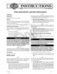
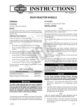
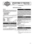
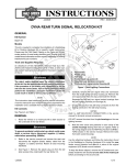
-J01875
REV. 2007-04-02
FLHT OIL PRESSURE AND AIR TEMPERATURE GAUGE KIT
GENERAL
is04574
Kit Number
1
77439-00 - Complete Kit
2
77459-00 - Installation Hardware Only (No Gauges)
3
Models
For model fitment information, please see the P&A Retail Catalog or the Parts and Accessories section of www.harleydavidson.com (English only).
LOCTITE®
Separate purchase of
565 Thread Sealant is
required for proper installation of this kit. LOCTITE can be
purchased from any Harley-Davidson Dealer.
2004 and Later Models: Do not require installation of items
6, 7 and 8 from this kit.
The rider's safety depends upon the correct installation
of this kit. Use the appropriate service manual procedures.
If the procedure is not within your capabilities or you do
not have the correct tools, have a Harley-Davidson dealer
perform the installation. Improper installation of this kit
could result in death or serious injury. (00333a)
w
w
NOTE
w.
4
1.
2.
3.
4.
o p. d e
Rosto
ck
Separate purchase and installation of additional parts or
accessories may be required for proper installation of this kit
on your model motorcycle. Please see the P&A Retail Catalog
or the Parts and Accessories section of www.harleydavidson.com (English only) for a list of required parts or
accessories for your model.
Oil pressure sending unit
Cam position sensor
Crank position sensor
Main harness to ECM
Figure 1. Electrical Bracket: 2000-2001 Fuel Injected Models
(Magnetti-Marelli)
is04575
h d o nli
sh
Additional Parts Required
erman
G
.
e
.
y
n
1
n
e
2
3
This instruction sheet references Service Manual information.
A Service Manual for your model motorcycle is required for
this installation and is available from a Harley-Davidson Dealer.
Kit Contents
See Figure 9 and Table 1.
INSTALLATION
Oil Pressure Sending Unit
To prevent accidental vehicle start-up, which could cause
death or serious injury, disconnect negative (-) battery
cable before proceeding. (00048a)
1.
1. Oil pressure sending unit
2. Crankshaft position sensor
3. P&A siren kit
Figure 2. Electrical Bracket (ECM Removed) 2002-2003
Fuel Injected Models (Delphi)
Refer to the Service Manual and follow the instructions
given to remove the seat and disconnect the battery
cables, negative (-) cable first.
-J01875
1 of 4
NOTE
For 2002 to 2003 models: See Figure 2. Remove the two
screws securing the ECM and remove the ECM to access the
electrical bracket.
2.
For 2004 and later models: Proceed to the Gauges
section.
For 2000 to 2003 models: See Figure 1, Figure 2 and
Figure 3 for the applicable model and locate the sensor
harness connector (2-piece mini-Deutsch® connector).
is04576
6.
Gently depress terminal latches inside pin housing and
back out the pin in chamber #1 through the hole in wire
seal.
7.
Pull the oil sending unit wire through conduit and remove
wire. Note the routing of the wire.
8.
See Figure 9. Route the jumper (6) pins through the conduit from the kit in the same direction as the original wire
noted in Step 7. Use cable straps to secure to the wire
bundle.
9.
See Figure 5. Locate pin chambers #1 and #2 on pin side
of connector. Insert brown/green jumper pin into chamber
#2 and feed until it clicks into place. Verify that pin will not
back out of the chamber by giving a slight tug on the wire
to confirm that it is locked.
3
2
is04578
4
Ignition harness
Cam position sensor
Oil pressure sending unit
Crankshaft position sensor
o p. d e
1.
2.
3.
4.
Rosto
ck
1
erman 1
G
.
e
.
y
n
Figure 3. Ignition Module - Carbureted Models
Locate the oil pressure sending unit at the front right side
of the crankcase and pull wire socket from terminal of the
oil pressure sending unit.
4.
Carefully draw the conduit and the pin side of mini-Deutsch
connector forward and then up between the rear brake
master cylinder reservoir and the frame downtube to area
of the rear brake pedal.
w
See Figure 4. Remove the secondary locking wedge (3)
from the pin side of the connector with a needle nose
pliers.
w
5.
is04577
1
w.
1. Sending unit jumper wires
Figure 5. Route Oil Sending Unit Connector
sh
3.
10. Insert green/yellow jumper pin to chamber #1 and repeat
steps performed in Step 9.
e
11. Insert tapered end of secondary locking wedge into the
pin housing and press down until it snaps in place. The
wedge fits in the center groove within the pin housing and
holds the terminal latches tightly closed.
h d o nli
n
12. Remove original oil pressure sending unit from crankcase
with a 15/16 inch open end crow foot wrench.
13. Apply LOCTITE® 565 Thread Sealant to threads on the
new oil pressure sending unit.
3
2
14. See Figure 9. Start the oil pressure sending unit (7) into
crankcase bore. Tighten switch to 8-10 ft-lbs (11-14 Nm)
with a 1-1/16 inch open end crow foot wrench.
15. Attach connector to oil pressure sending unit.
Gauges
1. Pin
2. Wire seal
3. Locking wedge
Figure 4. Deutsch Connector Pin Side (2-pin connector
shown)
-J01875
1.
Follow applicable Service Manual instructions to remove
the outer fairing.
2.
Remove plastic plugs from the gauge holes in inner fairing.
3.
See Figure 9. Install gauges (1 and 2) in the inner fairing.
While seated on the motorcycle, the air temperature gauge
installs in the hole on the left side of the radio tray, and
2 of 4
the oil pressure gauge installs in the hole on the right side
of the radio tray.
4.
For each gauge, slide back clamp (4) over the gauge
studs. Verify that the tab (A or B) on bracket engages slot
at bottom of inner fairing bore.
5.
Loosely install hex nuts (5) on studs. Verify that the gauge
is properly aligned and then tighten nuts securely.
6.
For 2000-2007 Models: See Figure 6. Install the air temperature sensor in the location shown (2) by pushing the
post on the connector into the hole in the fairing support.
After installing seat, pull upward on seat to be sure it is
locked in position. While riding, a loose seat can shift
causing loss of control, which could result in death or
serious injury. (00070b)
is04582
2
For 2008 and Later Models: See Figure 7. Remove frame
plug (1). Push sensor post into hole to install sensor.
Secure wire harness with cable strap from the kit.
1
3
is04579
erman
G
.
e
.
y
n
1. Frame plug
2. Air temperature sensor
3. Steering head
2
o p. d e
Rosto
ck
1
Figure 7. Location of Air Temperature Sensor - 2008 and
Later Models
1. Air temperature gauge
2. Air temperature sensor location
is04580
2
1
BK
Figure 6. Location of Air Temperature Sensor (outer fairing
removed) - 2000-2007 Models
See Figure 8. Refer to the wire colors on the schematic
to locate interconnect wire harness connectors 112, 113,
114, 115, and 107. Mate interconnect wire harness connectors to the gauges and sensor as shown in the
schematic.
w
w
8.
w.
h d o nli
n
e
O
BN
O
GN
BK
3
BE
O
V
BK
Follow applicable Service Manual instructions to install
the outer fairing.
Connect positive (+) battery cable first. If positive (+) cable
should contact ground with negative (-) cable connected,
the resulting sparks can cause a battery explosion, which
could result in death or serious injury. (00068a)
9.
sh
7.
BK
O
Refer to the Service Manual and follow the instructions
given to install the battery, positive cable first.
10. Refer to the Service Manual, and follow instructions to
install the seat.
-J01875
4
1.
2.
3.
4.
Oil pressure
Air temperature
Lead wires from interconnect harness
Air temperature sensor
Figure 8. Wiring Schematic
3 of 4
SERVICE PARTS
is04581
5
3
7
5
4
A
6
1
erman
G
.
e B
.
y
n
Rosto
ck
4
8
o p. d e
2
Figure 9. Service Parts: FLHT Gauge Kit
Item
Table 1. Service Parts Table
Description (Quantity)
1
Air temperature gauge
2
Oil pressure gauge
3
Air temperature sensor
4
Back clamp, 2-inch (2)
5
Metric hex nut (4)
6
Jumper, oil pressure gauge
7
Sending unit, oil pressure
8
Conduit
Part Number
75109-96B
w
w
sh
75032-99A
w.
hdon
n
li
e
74419-96A
67352-96
67043-96
32806-00
74438-99
Not Sold Separately
Items mentioned in text, but not included in kit:
-
Light bulb, replacement
A
Alignment tab
B
Alignment tab
-J01875
67445-00
4 of 4