1
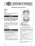
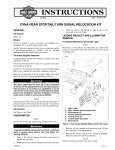
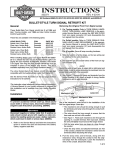
-J04646
REV. 2008-06-26
DYNA REAR TURN SIGNAL RELOCATION KIT
GENERAL
is05268
3
Kit Number
68227-09
6
Models
5
This kit is needed to complete the installation of a Saddlebag
Kit or Docking Hardware Kit on specific model motorcycles.
Please see the P&A Retail Catalog or the Parts and Accessories section of www.harley-davidson.com (English only) for
model fitment information and the correct Saddlebag or Docking
Hardware Kit part numbers.
4
An UltraTorch UT-100 (HD-39969), Robinair Heat Gun (HD25070) with Heatshrink Attachment (HD-41183), or other suitable radiant heating device is required for the proper installation
of this kit.
Figure 1. Rear Lighting Connections
4.
NOTE
w
w
This instruction sheet references service manual information.
A service manual for your model motorcycle is required for this
installation and is available from a Harley-Davidson dealer.
Kit Contents
See Figure 4 and Table 1.
w.
Raise the vehicle on a motorcycle lift to allow access to
the underside of the rear fender.
Separate the four-way turn signal socket housings from
the rear lighting harness pin housings (6).
5.
To prevent accidental vehicle start-up, which could cause
death or serious injury, disconnect negative (-) battery
cable before proceeding. (00048a)
2.
Refer to the service manual and remove the seat and
disconnect the negative (black) battery cable from the
negative (-) battery terminal. Retain all seat mounting
hardware.
3.
See Figure 1. Remove the plastic plug (2) from the tail
lamp access hole underneath the rear fender (1).
n
e
Unplug the gray four-way tail lamp connector (5) from the
mating connector in the tail lamp housing.
NOTES
Refer to AMP MULTILOCK CONNECTORS in the service
manual for terminal removal procedures.
DO NOT remove the wires from the pin housings on the rear
lighting harness.
6.
-J04646
Carefully remove the turn signal wires and connectors
from the inside of the tail lamp housing (3). Remove the
turn signal wires from the clips underneath the fender.
h d o nli
REMOVAL
1.
Rear fender
Plastic plug
Tail lamp
Socket head cap screw (3)
Gray four-way tail lamp connector
Four-way turn signal socket housing (2)
sh
The rider's safety depends upon the correct installation
of this kit. Use the appropriate service manual procedures.
If the procedure is not within your capabilities or you do
not have the correct tools, have a Harley-Davidson dealer
perform the installation. Improper installation of this kit
could result in death or serious injury. (00333a)
1.
2.
3.
4.
5.
6.
2
o p. d e
Rosto
ck
Tools and Supplies Required
erman
G
.
e
1
.
y
n
Note the wire colors and positions in each cavity of the
socket housings leading from the turn signals. Refer to
the wiring diagram and the AMP MULTILOCK CONNECTORS section in the service manual. Remove the wires
from both socket housings.
NOTE
Use the attaching hardware and follow the instructions found
in the Saddlebag or Docking Hardware Kit to install the new
fender mount brackets from this kit in place of the original
equipment (OE) fender mount brackets.
To keep the fender aligned, remove the OE bracket and completely install the new bracket on one side of the motorcycle
before proceeding to the second side.
1 of 4
See Figure 2. Remove the screw (2) at the front of the
fender mounting bracket (1).
NOTE
The spacer (3) is glued to the fender, and is not removed.
8.
Remove screw (4) and washer (5) at the rear of the fender
mounting bracket. Remove the turn signal lamp (6), support (7) and fender mounting bracket from the vehicle.
is05283
1
3
Be sure to follow manufacturer's instructions when using
the UltraTorch UT-100 or any other radiant heating device.
Failure to follow manufacturer's instructions can cause a
fire, which could result in death or serious injury. (00335a)
•
Avoid directing heat toward any fuel system component.
Extreme heat can cause fuel ignition/explosion resulting
in death or serious injury.
•
Avoid directing heat toward any electrical system component other than the connectors on which heat shrink work
is being performed.
•
Always keep hands away from tool tip area and heat shrink
attachment.
3.
Use a heat gun or suitable radiant-heating device to shrink
the tubing to the wires and conduit.
4.
Install the turn signal lamp wires through the small hole in
the rubber recess cover, and position the cover into the
recess in the turn signal housing.
2
4
5
6
7
erman
G
.
e
.
y
n
5.
Fender mounting bracket
TORX screw
Spacer
Hex head screw
Washer
Turn signal lamp
Turn signal lamp support
Rosto
ck
1.
2.
3.
4.
5.
6.
7.
NOTE
Check that the turn signal wires are not pinched, and that the
lockwasher will seat against the turn signal housing, not the
rubber recess cover.
Figure 2. Remove Turn Signal Lamp from Fender
INSTALLATION
6.
Turn Signal Installation
NOTE
w
w.
sh
w
For Wide Tire Installations: See Figure 4. Cut two pieces
of shrink tubing (6) into two equal length pieces.
Tighten the brackets to the torque values indicated in
those instructions.
h d o nli
For All Models: Slide one piece of shrink tubing over the
turn signal wires, all the way up to the lamp housing. Allow
1/2 - 3/4 inch (13-19 mm) of the tubing to remain covering
the conduit.
For Wide Tire Installations: Slide a second piece of
shrink tubing over the connector end of the turn signal
wires to cover the exposed, colored wiring.
n
e
7.
Align the turn signal housing so that the lens is aimed
straight rearward for proper visibility. While holding the
turn signal housing in position, tighten the hex nut and
lock washer against the housing (not the rubber recess
cover) to 96-120 in-lbs (11-14 Nm).
8.
Repeat Steps 2 through 7 for the opposite side of the
vehicle.
9.
Refer to AMP MULTILOCK CONNECTORS in the service
manual for terminal installation procedures.
For All Other Models: See Figure 4. Cut one piece of
shrink tubing (6) into two equal length pieces.
2.
Align the relocation bracket with the rear of the fender
support, and fit the round pad into the mating hole in the
support.
Follow the instructions in the Saddlebag or Docking
Hardware Kit, and use the specified hardware to install
the rear fender mounting bracket (1) and turn signal relocation bracket to the rear fender and vehicle frame fender
support.
The turn signal relocation brackets are side-specific. The
brackets install with the support tube above the level of the
fender support.
1.
Loosely install the hex nut (3) and lockwasher (4) onto the
short, threaded end of the turn signal relocation bracket
(2). Assemble the turn signal lamp and recess cover onto
the threads, but do not fully tighten.
o p. d e
7.
Install the turn signal wires and terminals into each cavity
of the turn signal socket housings. Refer to the service
manual wiring diagram and the notes made earlier.
10. Route the turn signal wires under the turn signal relocation
bracket and under the rear fender edge on each side of
the vehicle. Connect the turn signal socket housings to
the pin housings on the rear lighting harness.
11. Plug the gray four-way tail lamp connector on the rear
lighting harness into the mating connector in the tail lamp
housing under the fender.
-J04646
2 of 4
12. Gently push the turn signal wires and connectors into the
cavity inside the tail lamp housing. Install the plastic plug
into the tail lamp access hole in the rear fender.
13. Capture the turn signal wires beneath the clips at the sides
of the reinforcement bracket on the underside of the fender
and at the back of the rear fender mounting bracket.
a.
Do not pull the turn signal wires tight against the
fender edges or the turn signal relocation brackets.
b.
Check that there are no loose wires in the wheel
compartment.
15. Use a mixture of 50 to 70% isopropyl alcohol and 30 to
50% distilled water to clean the bottom edge of the fender
on each side, at the point where the turn signal wiring
crosses under the fender. Allow to dry thoroughly.
Obtain the protective edging (8) from the kit, and cut into
two equal-length pieces.
Carefully position the edging around the bottom edge of
the fender, and press firmly into place to prevent the turn
signal wire from rubbing on the fender edge.
After pressing in place, apply heat to the edging using a
heat gun or radiant-heating device, held 3-6 inches (75150 mm) away from the edging for 10-15 seconds.
Adjust the wire routing if necessary.
14. See Figure 3. Route the turn signal wire (2) along the
underside of the relocation bracket (1). Tie the wire to the
bracket, just forward of the 90 degree bend, with a cable
strap (3) from the kit.
is05331
NOTE
Allow AT LEAST 24 hours after applying the edging before
exposing the area to vigorous washing, strong water spray or
extreme weather.
FINAL ASSEMBLY
erman
G
.
3
e
.
y
n
Apply a light coat of petroleum jelly or corrosion retardant
material to the negative battery terminal. Refer to the service manual connect the negative battery cable.
1
2.
Figure 3. Wire Routing Along Bracket
NOTE
Ambient temperature should be at least 60 °F (16 °C) for
proper adhesion of the protective edging to the fender.
w
-J04646
w.
o p. d e
After installing seat, pull upward on seat to be sure it is
locked in position. While riding, a loose seat can shift
causing loss of control, which could result in death or
serious injury. (00070b)
2
1. Relocation bracket
2. Turn signal wire
3. Cable strap
w
Verify that the ignition/key switch is turned to the OFF
position.
Refer to the service manual and follow instructions to
install the seat.
Be sure that all lights and switches operate properly before
operating motorcycle. Low visibility of rider can result in
death or serious injury. (00316a)
3.
sh
Rosto
ck
1.
e
Check the turn signals and the rest of the rear lighting for
proper operation.
h d o nli
n
3 of 4
SERVICE PARTS
is05300
Table 1. Service Parts
Item
1
8
2
B
C
7
4
5
A
2
Turn signal relocation bracket (2)
(right-side shown, left opposite)
Not sold separately
3
Hex nut (2)
7849
4
Lock washer (2)
7042
5
Recess cover, rubber (2)
68749-09
6
Heat-shrink tubing,
6 inch (152 mm) long (2)
Not sold separately
7
Cable strap (2)
10065
8
Protective edging
68877-09
Items mentioned in text, but not included in kit.
A
Turn signal assembly (2)
B
Rearward attaching hardware
(from Saddlebag or Docking Hardware Kit)
C
Original equipment forward attaching hardware
o p. d e
erman
G
.
e
.
y
n
w
w
-J04646
Rear fender mounting bracket (2) 59542-09
sh
Rosto
ck
Figure 4. Service Parts, Dyna Rear Turn Signal Relocation
Kit
Part Number
1
6
3
Description (Quantity)
w.
h d o nli
n
e
4 of 4