1
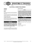
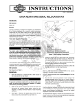
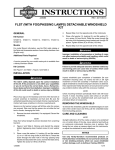
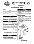
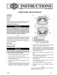
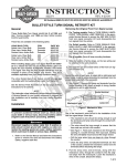
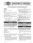
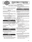
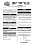
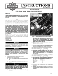
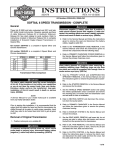
INSTRUCTIONS
REV. 10-4-2004
-J03354
®
Kit Number 50743-04
FOOTBOARD EDGE LIGHT KIT
General
i06907
1
This kit is designed for use on all models with original
equipment rider foot boards except for 2005 FLSTN/I model
motorcycles.
1WARNING
The rider's safety depends upon the correct installation
of this kit. If the procedure is not within your capabilities
or you do not have the correct tools, have a HarleyDavidson dealer perform the installation. Improper
installation of this kit could result in death or serious
injury. (00308a)
erman
G
.
e
.
y
n
1. Remove the seat according to the applicable Service
Manual instructions.
1WARNING
To prevent accidental vehicle start-up, which could
cause death or serious injury, disconnect battery cables
(negative cable first) before proceeding. (00048a)
1.
2.
3.
2
3
Left side foot board
Rubber bumper tabs (3)
Lighted footboard cover
o p. d e
Removal
Rosto
ck
NOTE
A Service Manual for your model motorcycle is available
from your Harley-Davidson Dealer.
Figure 1. Lighted Footboard Cover Installation
3. Starting with the center hole, apply upward pressure to
the light housing (3) and using pliers, pull down on
rubber bumper tab until light is seated onto tab. Repeat
for left and right side tabs.
1WARNING
Disconnect negative (-) battery cable first. If positive (+)
cable should contact ground with negative (-) connected, the resulting sparks can cause a battery explosion,
which could result in death or serious injury. (00049a)
w
w
w.
2. Disconnect battery cables, negative cable first.
sh
4. Repeat procedure for right side footboard.
Routing Wiring
h d o nli
3. On Softail models only, remove the battery in order to
route the electrical wiring up to the battery area.
Installation
1. See Figure 1. Starting with the left side footboard (1), tilt
footboard to the upright position for access to bottom of
footboard.
2. Using a window cleaning solution, spray the three
rubber bumper tabs (2) protruding through the bottom of
the footboard.
n
e
NOTE
Wiring for the right side footboard light will run from the front
of the footboard. Wiring for the left side footboard light will
run from the back of the footboard.
1WARNING
Failure to provide clearance between stationary and
moving parts can cause loss of control, which could
result in death or serious injury. (00378a)
IMPORTANT NOTE
Ensure that footboard harness wires are routed so as not to
come in contact with footboard swivel hinge, drive belt,
exhaust pipe jiffy stand or sharp edges.
All Models: Starting with the left side foot board, route
wire across footboard right front bracket to underside of
vehicle frame. Secure wire with short wire ties. Continue
running wire toward rear of vehicle along bottom of
frame until you reach the vertical frame support. Secure
wires along bottom frame.
1 of 4
Feed wire up vertical frame support taking care that
wire does not contact drive belt. Feed wire up into
battery compartment area. Secure wire along vertical
frame support using two long wire ties from kit. Repeat
wire installation on right side of vehicle.
i06934
1
Electrical Connections – All 1994 and
Later Touring Models
2
5
1. See Figure 2. Plug the right (1) and left (2) light assembly
wiring harnesses into the footboard wiring harness (3)
supplied in the kit.
2. Connect the footboard wiring harness connector (4) into
the accessory plug located under the seat. Proceed to
FINAL ASSEMBLY.
7
3
1
4
i06935
erman 5
G
.
e
.
y
6
n
Figure 2. Electrical Connections – All 1994 and Later
Touring Models
5. Black wires (Ground)
6. Ring terminal (1/4 in)
7. Orange wires
8. Pre-insulated, seal
splice connector
9. Accessory circuit wire
(orange or orange/white)
1. Right light assembly
wiring harness
2. Left light assembly
wiring harness
3. Footboard wiring
harness
4. Duetsch connector
Figure 3. Electrical Connections
(All Softail Models)
i06828
Electrical Connections – All Softail
Models
w
w.
9
8
o p. d e
2
3. Footboard wiring
harness
4. Footboard wiring
harness connector
w
7
9
4
1. Right light assembly
wiring harness
2. Left light assembly
wiring harness
2
sh
1
Rosto
ck
3
NOTE
On all Softail models it is necessary to splice the adapter
harness into the existing wiring. Pre-insulated ring terminal
and butt connectors are included in this kit.
hdon
n
li
e4
2
3
1. See Figure 3. Plug the right (1) and left (2) light assembly
wiring harnesses into the footboard wiring harness (3)
supplied in the kit.
1
2. Remove the Duetsch connector (4) according to the
instructions in the applicable Service Manual.
3. Cut the existing terminal from the black wire (5), as close
to the connector as possible. Strip a 3/8 in. (10 mm)
section of insulation from the end of the black wire and
install a ring terminal (6) supplied in the kit.
4. See Figure 4. Connect the ring terminal to a ground stud
(1) located under the seat.
-J03354
1.
2.
3.
4.
Ground stud
Accessory wiring circuit (orange or orange/white
wire)
Wire bundle area
Plastic wire channel
Figure 4. Electrical Connections Locations
NOTE
See Splicing Information (All Softails Models) for detailed
usage information for sealed-splice connectors.
2 of 4
5. See Figure 3. With the Duetsch connector disassembled,
strip insulation from the orange wire (or orange/white) and
install a pre-insulated, seal splice connector (8) supplied
in the kit.
4. Match the color of the butt splice connector with the
color of the crimp cavity of the crimping tool. Using an
Crimping Tool (H-D 38125-8), crimp the wires into the
connector.
6. See Figure 5. Splice the other end of the connector into
an accessory wiring circuit (9) on the main harness near
the rear lighting connector (2) under the seat (orange or
orange/white wire).
1WARNING
7. Route wires into plastic wire channel (4) and bundle
excess wires and place at front of battery (3). Proceed
to FINAL ASSEMBLY.
i05735
1
Be sure to follow manufacturer's instructions when
using the UltraTorch UT-100 or any other radiant heating
device. Failure to follow manufacturer's instructions can
cause a fire, which could result in death or serious
injury. (00335a)
•
Avoid directing heat toward any fuel system component. Extreme heat can cause fuel ignition/explosion
resulting in death or serious injury.
•
Avoid directing heat toward any electrical system
component other than the connectors on which heat
shrink work is being performed.
•
r
e
man
G
.
e
y
n.
Always keep hands away from tool tip area and heat
shrink attachment.
3
Final Assembly
Stripped wire ends inserted in connector
Wire ends crimped in connector
Connector after heat has been applied
1WARNING
Connect positive (+) battery cable first. If positive (+)
cable should contact ground with negative (-) cable connected, the resulting sparks can cause a battery explosion, which could result in death or serious injury.
(00068a)
Figure 5. Install Sealed Butt Connectors
Splicing Directions
1. Cut the terminals off the wires as close to the terminals
as possible.
w
w
2. Strip a 3/8 in. (10 mm) section of insulation from the end
of each wire to be spliced.
w.
sh
1
2
3
o p. d e
Rosto
ck
2
Using UltraTorch UT-100 (H-D 39969), Robinair Heat Gun
(H-D 25070) with heatshrink Attachment (H-D 41183), or
other suitable radiant heating device, heat the crimped
splice to encapsulate the butt spice connector. Apply heat
from the center of the crimp out to each end until the
meltable sealant exudes out of both ends of the connector.
1. Connect the battery cables, positive cable first.
h d o nli
3. See Figure 5. For each splice, insert the wire ends into
the splice connector as shown.
n
e1
WARNING
After installing seat, pull upward on front of seat to be
sure it is in locked position. While riding, a loose seat
can shift causing loss of control, which could result in
death or serious injury. (00070a)
2. Install the seat according to the procedure in the
applicable Service Manual.
-J03354
3 of 4
®
Service Parts
Part No. 50743-04
Date 10/04
Footboard Edge Light kit
i06912
2
1
3
Rosto
ck
4
erman
G
.
e
.
y
n
1
4
-J03354
5
w
Part No.
50744-04
70281-03A
w.
70586-93
9863
Item
5
6
sh
Description
Footboard Edge Light (2)
Wiring Harness, Footboard
Connector, Pre-insulated,
Seal Splice (2)
Ring Terminal, Pre-insulated,
1/4 in. ID
w
Item
1
2
3
o p. d e
6
e
Description
Strap, Cable (12)
Strap, Cable (long) (4)
h d o nli
n
Part No.
10006
10039
4 of 4