1
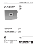
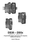
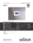
PVMate
Grid Connected PV Inverter
with
Operating Manual
MOTECH INDUSTRIES INC.
6F, No. 248, Sec. 3, Bei-Shen Road, Shen-Keng District, New
Taipei City 22204, Taiwan
Tel: +886-2-26625093 +886-2-26625194
Fax: +886-2-26625097
E-mail: [email protected]
Web site: www.motech.com.tw
© MOTECH 2010 All rights reserved
ZOMG-814ME-1B
65
Table of Contents
1.
INTRODUCTION ............................................................................ 1
1.1
GENERAL .................................................................................. 1
1.2
SPECIFICATIONS ........................................................................ 3
1.3
ADJUSTABLE PARAMETER SETTINGS ........................................... 5
1.4
ACCESSORIES ........................................................................... 6
2.
3.
SAFETY ......................................................................................... 7
2.1
SAFETY PRECAUTIONS/SAFETY NOTES ....................................... 7
2.2
SAFETY SYMBOLS ...................................................................... 7
2.3
INTENDED USE .......................................................................... 8
2.4
GENERAL SAFETY PRECAUTIONS ................................................ 8
2.5
SAFE INSTALLATION AND OPERATION .......................................... 9
2.6
REPAIR AND MAINTENANCE ...................................................... 10
INSTALLATION ............................................................................. 11
3.1
PLACEMENT..............................................................................11
3.2
MOUNT.................................................................................... 12
3.3
W IRING THE INVERTER ............................................................. 17
3.3.1 Connection of the AC cable ...................................................... 19
3.3.2 Connection of the DC cable ...................................................... 22
3.3.3 Connection of the Communication cable ................................ 25
3.4
4.
64
W IRING INVERTER IN PARALLEL ................................................. 29
OPERATION .................................................................................. 31
4.1
OVERVIEW ............................................................................... 31
4.2
OPERATION FEATURE ............................................................... 33
4.3
LED INDICATION ...................................................................... 35
4.4
LCD DISPLAY........................................................................... 38
4.5
COMMUNICATION ..................................................................... 48
4.6
EXPLANATIONS OF ERROR MESSAGES ...................................... 48
5.
WARRANTY INFORMATION ........................................................ 51
6.
TECHNICAL DOCUMENTATION .................................................. 55
6.1
OUTLINE DRAWING .................................................................. 55
6.2
EFFICIENCY ............................................................................. 57
6.3
DE-RATING OPERATION ............................................................ 59
63
List of Figures
PVMATE3300MS
4000
3000
Pac(W)
200Vdc
2000
350Vdc
400Vdc
1000
Fig1.1.1
Grid Connected Solar System Overview ..................................... 2
Fig3.1.1
Clearances required for PVMate inverter installation ................ 12
Fig3.2.1
Remove side screws and bracket ............................................. 13
Fig 3.2.2 Mount bracket ............................................................................ 14
Fig 3.2.3 Fasten the mount bracket .......................................................... 15
Fig 3.2.4 Hooking inverter onto the bracket ............................................. 16
0
25
30
35
40
45
50
55
60
65
70
75
80
Fig 3.2.5 Fasten the inverter with two side screws................................... 17
Ambient(℃
℃)
Fig 3.3.1 Wiring compartment front view .................................................. 18
Fig 6.3.3 Temperature derating curve of the PVMate3300MS-AU
Fig 3.3.2 Wiring compartment bottom view .............................................. 19
PVMATE2500
3000
2000
Pac(W)
200Vdc
350Vdc
1000
400Vdc
0
25
30
35
40
45
50
55
60
65
70
75
80
Ambient(℃
℃)
Fig 6.3.4 Temperature derating curve of the PVMate2500-AU
Fig 3.3.1.1
Assembly of the AC cable and the AC connector ................. 21
Fig 3.3.2.1
DC terminals for DC cable connection .................................. 23
Fig 3.3.2.2
DC terminals for DC cable connection .................................. 23
Fig 3.3.2.3
PV- terminal connection ........................................................ 24
Fig 3.3.2.4
PV+ terminal connection ....................................................... 24
Fig 3.3.3.1
Communication default setting .............................................. 25
Fig 3.3.3.2
Communication cable inside the tube ................................... 26
Fig 3.3.3.3
RJ-45 Pins and Signals ......................................................... 27
Fig 3.3.3.4
RS-232 connection................................................................ 27
Fig 3.3.3.5
RS-485 connection................................................................ 28
Fig 3.3.3.6
Assembly of the waterproof RJ-45 plug ................................ 28
Fig 3.3.3.7
Pin number of the Waterproof RJ-45 plug ............................ 29
Fig 3.4.1 Parallel configuration of inverter ................................................ 30
Fig 4.2.1 Master/Slave Mode Wirings ...................................................... 34
Fig 4.3.1 Front panel of the PVMate inverter ........................................... 36
Fig 4.4.1 PVMate inverter LCD display lay-out ........................................ 47
62
PVMATE4600MS
Fig 6.1.1 Outline Drawing(4600MS-AU/3800MS-AU/3300MS-AU) ......... 55
Fig 6.1.2 Outline Drawing (2500-AU) ....................................................... 56
5000
Fig 6.2.1 Efficiency of the PVMate4600MS-AU ........................................ 57
4000
Fig 6.2.2 Efficiency of the PVMate3800MS-AU ........................................ 57
Fig 6.2.3 Efficiency of the PVMate3300MS-AU ........................................ 58
Pac(W)
3000
200Vdc
350Vdc
2000
400Vdc
Fig 6.2.4 Efficiency of the PVMate2500-AU ............................................. 58
1000
Fig 6.3.1 Temprature derating curve of the PVMate4600MS-AU ............. 61
0
Fig 6.3.2 Temprature derating curve of the PVMate3800MS-AU ............. 61
25
30
35
40
45
55
60
65
70
75
80
Ambient(℃
℃)
Fig 6.3.3 Temprature derating curve of the PVMate3300MS-AU ............. 62
Fig 6.3.4 Temprature derating curve of the PVMate2500-AU .................. 62
50
Fig 6.3.1 Temperature derating curve of the PVMate4600MS-AU
PVMATE3800MS
4000
3000
Pac(W)
200Vdc
2000
350Vdc
400Vdc
1000
0
25
30
35
40
45
50
55
60
65
70
75
80
Ambient(℃
℃)
Fig 6.3.2 Temperature derating curve of the PVMate3800MS-AU
61
will still automatically restrict the delivery output current to keep the output
power within the maximum power limit when the output voltage is too
high.
1.
Introduction
1.1
General
Output AC current
The maximum current that the PVMate inverter feeds to the grid is limited
according to the specifications listed in Section 1.2. Even the output
power does not reach the maximum power limit the PVMate inverter will
still restrict the delivery output current within the maximum current limit
when the output voltage is too low.
The Motech Industries PVMate product family is a series of
grid-connected photovoltaic inverters with FLEX-MPPTs that is a method
for multiple MPPT system implementation. PVMate inverters utilize the
FLEX-MPPTs technology to efficiently absorb more energy from the PV
panels during reduced solar irradiation. The PVMate is designed to
convert DC power produced by photovoltaic arrays to AC voltage that is
then fed into the mains electricity grid network. The PVMate family
Output AC voltage
When the inverter is connected to a grid system with longer or thinner
wirings, it’s output voltage might be higher than the over voltage setting.
This will cause disconnection due to the voltage deviation instead of
abnormal voltage happened in the grid. PVMate inverter provides a
setting of voltage quality monitoring which is less than the setting of over
voltage. Once the AC voltage reach the voltage quality monitoring setting,
PVMate inverter will restrict the output current to keep the AC voltage stay
equal to or less than the setting of AC over voltage so that the inverter,
instead of shut itself down, keeps output power to the grid although it is
not the maximum output power.
currently contains four (4) members which are PVMate4600MS-AU,
PVMate3800MS-AU, PVMate3300MS-AU and PVMate2500-AU. An
overview of the grid-tied solar energy system with a three (3) string PV
module configuration connected inverter is shown in figure 1.1.1. PVMate
inverters comply with all VDEW (German Electricity Association)
regulations for supplementary grid feeding to low voltage electricity grid
networks (110V-270V). Additionally, PVMate inverters are also certified to
comply with the latest regulations (Refer the certification lists of 1.2
Specifications).
The PVMate inverter is designed to support up to three (3) PV strings
depending on PVMate power rating and will operate automatically without
any configuration once it is installed and commissioned according to the
technical specifications. When at least one of the DC input voltages
generated by the photovoltaic module goes above the pre-set threshold
value setting and under the PV start voltage, the embedded controller is
then awakened to remain in System Check mode because the PV start
60
1
voltage is not yet reached. At this time, the PVMate inverter would not
feed the AC power to the mains utility; instead, it keeps watching the input
DC voltage. Once the input DC voltage goes up above the PV start
voltage and all other conditions necessary for grid connection are
checked and fulfilled for a certain period of time, the PVMate inverter
goes into the Grid/MPP mode that turns the AC relays on and begins
feeding the AC power into the grid steadily. When all of the input DC
voltages fall below the minimum MPP voltage setting which is 100 VDC,
the PVMate inverter will then shut itself down. The PVMate inverter will
return to operation automatically when one or more of the input DC
voltages go up above the PV start voltage setting.
6.3
De-rating Operation
The factors that the PVMate inverter will take into account resulting in
output regulation and/or restrict the input power to ensure the system is in
a safe operation are described in detail below.
Temperature
The PVMate inverter will monitor the temperature on the heatsink. Once
the temperature exceeds 72°C the system will reduce the output power
until the temperature drops under the critical value. The PVMate inverter
will shut down the power output to the grid if the temperature reaches
It is very much appreciated that you have chosen Motech PVMate
80°C. If this occasion happens often, it needs to c heck whether the
inverters as your power conversion device of choice for implementation of
inverter is mounted at an appropriate place with good ventilation and not
a solar power system. This document contains the information you need
exposed to direct sunlight; all temperature derating curves are illustrated
for the installation and settings of the PVMate inverters. Therefore, it is
in the figure 6.3.1 ~ figure 6.3.4.
strongly recommended to read this manual carefully before the PVMate
inverter installations and setup.
Input DC current
When any input current from the PV strings is about to exceed 10A, the
Utility Grid
String A
PVMate inverter will restrict it to the operating limit which is 10A per string
in order to prevent damages to the inverter. If this occasion happens
Fuse Box
frequently, it needs to check whether the PV arrays are configured
String B
properly to supply the DC current within the maximum limit which is 10A
String C
to the inverter.
Output AC power
PVMate Inverter
Photovoltaic Array
Load
Fig1.1.1 Grid Connected Solar System Overview
2
The maximum power that the PVMate inverter feeds to the grid is limited
according to the specifications listed in Section 1.2. Even the output
current does not reach the maximum current limit, the PVMate inverter
59
1.2
Specifications
PVMate3300MS-AU
Model Name
98
96
PVMate3800MS-AU
PVMate3300MS-AU
PVMate2500-AU
Grid Side (AC output)
94
Grid Voltage,
92
Eff(%)
PVMate4600MS-AU
230 VAC
90
200Vdc
88
350Vdc
86
400Vdc
84
Nominal
Grid Frequency,
50 / 60 Hz
Nominal
82
80
165
330
660
825
Nominal Output
990 1320 1650 1980 2310 2475 2640 2970 3300 3800
4600 W
3800 W
3300 W
2500 W
5000 W
4400 W
3800 W
2800 W
20 A
16.52A
14.35A
10.87A
22 A
19.13 A
16.52 A
12.18A
30 A
25 A
25 A
20 A
Power
Pac(W)
Maximum Output
Fig 6.2.3 Efficiency of the PVMate3300MS-AU
Power
Nominal Output
PVMate2500-AU
Current
Maximum Output
98
96
Current
94
Output over current
92
Eff(%) 90
200Vdc
88
350Vdc
86
400Vdc
84
82
125
250
500
625
750 1000 1250 1500 1750 1875 2000 2250 2500 2800
Pac(W)
Fig 6.2.4 Efficiency of the PVMate2500-AU
protection
(recommended)
Waveform
True sine
Power Factor
> 0.99
THD
< 3%
DC Component
< 0.5%
Phase
Single phase
PV Side (DC input)
Maximum DC
4500W per input port
Power
58
3
MPP Voltage Range
100 ~ 450 V
6.2
Maximum Input
Efficiency
500 VDC
Voltage
Efficiency of the PVMate inverters
Maximum DC
10A per input port
Current
No. of DC Input Port
3
2
2
1
No. of MPP Tracker
1~3
1~2
1~2
1
98
Model Name
PVMate4600MS-AU
PVMate3800MS-AU
PVMate3300MS-AU
PVMate2500-AU
96
PVMate4600MS-AU
94
General
Eff(%)
92
Maximum
96.3%
96.3%
96.3%
96.3%
Efficiency
@350VDC
@350VDC
@350VDC
@350VDC
88
European
95.4%
95.1%
95.1%
94.7%
86
Efficiency
@350VDC
@350VDC
@350VDC
@350VDC
200Vdc
90
350Vdc
400Vdc
84
230
460
920 1150 1380 1840 2300 2760 3220 3450 3680 4140 4600 5100
Pac(W)
Operating Ambient
-20°C ~ 55°C
Temperature
Relative Humidity
Fig 6.2.1 Efficiency of the PVMate4600MS-AU
Max. 95%
Mechanical
Enclosure
IP65 (ref. DIN EN60529)
Cooling
Weight
Cooling Fan
23 kg
22.5 kg
22.5 kg
Dimensions
580 x 422 x 182 (mm)
Display
LED / LCD
98
96
22 kg
Interface
Communication
PVMate3800MS-AU
Natural
RS232 and RS485
Certifications
94
92
Eff(%)
90
200Vdc
88
350Vdc
86
400Vdc
84
82
80
190
EMC
EN 55022 (Class B) & C-Tick, EN 61000-6-2, EN 61000-6-3,
(2004/108/EC)
EN 61000-3-11, EN 61000-3-12, EN 61000-3-2,
380
760
950 1140 1520 1900 2280 2660 2850 3040 3420 3800 4400
Pac(W)
Fig 6.2.2 Efficiency of the PVMate3800MS-AU
4
57
EN 61000-3-3, AS/NZS 61000.3.3, AS/NZS 61000.3.5
310
55.9
115
155
Low Voltage
EN 50178 (covered by IEC 62103),
AS/NZS
AS/NZS 3100
3100
(2006/95/EC)
580.2
36
180
Regulation
VDE 0126-1-1, RD 1663 / RD 661,
AS 4777.2,
Network Monitoring
DK 5940 / Enel Connections Guide (2008), Section F,
AS 4777.3
AS 4777.2, AS 4777.3
RoHS
421.8
198.6
1.3
2002/95/EC
Adjustable Parameter Settings
The PVMate inverters have, currently, four models to fulfill the market
needs for the countries of Germany, Italy, Spain and Australia. It can be
distinguished by the model names described as follows:
Fig 6.1.2 Outline Drawing (2500-AU)
•
PVMate xxxxMS
: For Germany
•
PVMate xxxxMS-IT
: For Italy
•
PVMate xxxxMS-ES : For Spain
•
PVMate xxxxMS-AU : For Australia
Parameter
Germany
Italy
Spain
PVMate xxxxMS
PVMate xxxxMS-IT
PVMate xxxxMS-ES
PVMate xxxxMS-AU
VDE0126-1-1
DK5940
RD1663, RD661
AS 4777.2, AS 4777.3
Over-voltage (VAC)
260.0
262.0
253.0
265.0
Under-voltage (VAC)
198.0
188.0
196.0
205.0
Over-frequency (Hz)
50.19
50.3
51.0
50.99
Under-frequency (Hz)
47.51
49.7
49.0
49.01
Model name
Standard
56
Australia
Over-voltage clearing time (cycle)
8
5
5
90
Under-voltage clearing time (cycle)
8
10
10
90
5
Over-frequency clearing time (cycle)
5
3
2
90
Under-frequency clearing time (cycle)
5
3
2
90
253.0
253.0
253.0
260.0
300
0 (NA)
0 (NA)
0 (NA)
20
20
180
20
130.0
130.0
130.0
130.0
Voltage quality monitoring* (VAC)
Voltage quality monitoring time* (s)
Reconnect delay (s)
PV start voltage (VDC)
6.
Technical Documentation
6.1
Outline Drawing
310
* The period of time for the PVMate inverter to disconnect from the grid and enter the
155
55.9
115
Monitoring mode after the detection of the AC voltage that is higher than the Voltage quality
monitoring setting and below the Over-voltage setting. This function is available only in the
Accessories
580.2
1.4
36
180
models of Germany type according to the VDE 0126-1-1, Clause 4.2.3.
PVMate4600MS-AU / PVMate3800MS-AU / PVMate3300MS-AU
Operating Manual
x1
AC Connector
x1
RJ-45 plug
x2
DC Connector Sealing Cap (female)
x1
DC Connector Sealing Cap (male)
x1
Jumper (for FLEX-MPPTs, see figure 4.2.1)
x2
Auto Test CD(Italy model only)
x1
421.8
198.6
Fig 6.1.1 Outline Drawing(4600MS-AU/3800MS-AU/3300MS-AU)
PVMate2500-AU
Operating Manual
x1
AC Connector
x1
RJ-45 plug
x2
6
55
NOTE:
Unauthorized returns will not be accepted and will be returned
at the shipper’s expense.
NOTE:
All component replacement and its service labor costs are
covered by the warranty in effect. Once the warranty expires, a
Product found upon inspection by MOTECH, to be in
specification is subject to an evaluation fee and applicable
freight charges, if any.
2.
Safety
2.1
Safety Precautions/Safety Notes
Only trained qualified electrical personnel are allowed to perform the
electrical installation, wiring, opening, repair, and/or modification of
PVMate inverters. Even when no external voltage is present, the PVMate
inverters can still contain high voltages and present a risk of electrical
shock.
The temperature of the heat sinks outside of the device can reach over
70°C in normal operation. There is the risk of burn injury when these parts
are touched.
The following general safety precautions must be observed during all
phases of operation, service, installation, modification, and repair of this
device. Failure to comply with these precautions or with specific warnings
elsewhere in this manual violates safety standards of design,
manufacture, and intended use of the device. The manufacturer assumes
no liability for the customer’s failure to comply with these requirements.
2.2
Safety Symbols
To reduce the risk of injury and to ensure the continued safe operation of
this product, the following safety instructions and warnings are marked in
this manual.
54
7
Warning, risk of electric shock
Presents safety information to prevent injury or death to
users and/or installers.
2. Isolation of the inverter from the external electrical environment under
the guidance of a qualified MOTECH service representative.
3. Full declaration of the environmental conditions currently in place and
Earth ground symbol
historically preceding the failure, including but not limited to the utility
grid connection and PV generator array configuration.
Caution (refer to accompanying documents)
Presents information to prevent damage to this product.
!
2.3
What Comes to Your Notice before Return
In case the Product fails to function and requires a Factory Service after
Intended Use
diagnosis, the Product could be sent back using the proper shipping box and
PVMate inverters shall be installed according to the safety regulations
the packing materials. A copy of the original purchase invoice is also
applied for installations to meet the following qualifications:
required to be included in the package. In addition, here are some
documents which be attached with the return Product. Please provide as
•
Electrical installation must be carried out correctly to meet the
much detail as possible.
applicable regulations and standards;
PVMate inverters shall be mounted in an enclosed and well ventilated
1. Model number and serial number shown on the label.
environment to against rain, condensation, moisture and dust;
2. Fault message on the panel and how it reproduces.
•
PVMate inverters shall be able to be permanently installed;
3. Detailed descriptions before & after the fault condition and the utility grid
•
PVMate inverters shall be installed according to the instructions stated
•
4. Whether or not the unit has had persistent faults despite servicing or has
in this manual;
•
PVMate
inverters
shall
operate
according
to
the
technical
specifications as stated in section 1.2;
2.4
•
General Safety Precautions
Personnel must remove all conductive jewelry or personal equipment
prior to installation or service of the device, parts, connectors, and/or
a fault history.
How Our Factory Service Occurs
1. Replace the defective Product with a new unit if it is purchased within
90 days.
2. Replace the defective Product with a refurbished unit if it is purchased
after 90 days.
wiring.
•
system connected.
Trained qualified personnel are required to mount, operate, correct
NOTE:
and/or repair this device.
All remaining warranty periods will remain effective for the
replacement inverter or parts.
8
53
2.
Damaged by external hazard or force majeure such as lightning strikes,
•
storm, and/or fire.
equipment.
3. Damaged by modifications, alterations or attachments thereto which are
•
not authorized by MOTECH.
Stand on an insulated surface when working on the operating device
(i.e., ensure that there is no grounding).
4. Transported, installed or operated contrary to this instructions of
•
MOTECH.
Instructions in this manual must be precisely followed and all
information on cautions or warnings must be adhered to.
5. Opened, altered, modified or disassembled in any way without
•
MOTECH’s consent.
The list does not contain all measures pertinent to the safe operation
of the device. If special problems arise which are not described in
6. Used in combination with items, articles or materials not authorized by
sufficient detail for the purposes of the buyer, contact your specialized
MOTECH.
dealer or technician.
MOTECH reserves the rights to determine whether the problem exists within
the Product. The Buyer may not assert any claim that the Products are not in
conformity with any warranty until the Buyer has made all payments to
•
Contact Solco for further warranty information or see the Solco
website for further updates.
•
The inverter must be provided with an equipment-grounding
conductor connected to the AC ground.
2.5
•
Safe Installation and Operation
Installation of the device must be in accordance with the safety
regulations (Refer the certification lists of 1.2 Specifications) and all
Product Return Procedure
other relevant national or local regulations. Correct grounding and
On-site Inspection & Repair
over-current protection must be provided to ensure operational safety.
If a Product requires warranty service, contact your merchant or MOTECH
directly. After your application is received, the service will be implemented by
our qualified technician in the installation field or in a designated MOTECH
service centre. Problem isolation processes include,
technician
Use proper lifting tools whenever handling enclosure, equipment or
parts.
MOTECH provided for in the Purchase Order Agreement.
1. Qualified service
Licensed electrician is required to install permanently wired
on site
with
Read all instructions and cautionary marks in the manual before the
installation of this device.
•
Switch off the circuit breakers before installation and wirings. Never
stand on a wet location when working on installation and wirings.
•
digital measurement
equipments, including but not limited to digital voltmeter and current
clamp meter.
•
Check both of the AC and DC connections with a volt meter prior to
any installation or removal procedures.
•
Enclose the outer covering sufficiently before switching on the AC and
DC circuit breakers.
52
9
•
Place the inverter in an environment with good ventilation and
adequate protection against rain, condensation, moisture and dust.
•
Even if no external voltage is applied; the PVMate inverter can still
contain high voltages and the risk of electrical shock. Allow 5 minutes
•
Warranty information
Warranty Period
for the inverter to discharge completely after disconnecting the AC and
A period of 5 years is warranted from the date of your purchase of the
DC sources from the inverter.
PVMate series Products.
Temperature of the heat sinks outside of the device can reach over
70°C in normal operation. There is the risk of burn injury when these
•
5.
Warranty Terms
parts are touched. Pay attention to high temperature components and
MOTECH INDUSTRIES INC. hereby provides this written Limited Warranty
sharp edges.
covering
Allow changes in your electrical system to be carried out only by
PVMate3800MS-AU, PVMate3300MS-AU and PVMate2500-AU, and if the
qualified electricians.
Buyer discovers and notifies MOTECH in writing of any defect in material or
2.6
Repair and Maintenance
The PVMate inverter contains no user serviceable parts. Only MOTECH
trained service staff are authorized to carry out for repairs and
the
Products
with
the
models
PVMate4600MS-AU,
workmanship within the applicable warranty period stated above, then
MOTECH may, at its option: repair or replace the Product; or issue a credit
note for the defective Product; or provide the Buyer with replacement parts
for the Product.
maintenance of the unit. Please return the device for repair and
The Buyer will, at its expense, return the defective Product or parts thereof
maintenance.
to MOTECH in accordance with the return procedure specified below.
MOTECH will, at its expense, deliver the repaired or replaced Product or
parts to the Buyer.
Exclusion of Liability
Any warranty of MOTECH will not apply if the Buyer is in default under the
Purchase Order Agreement or where the Product, any part or its original
label thereof is
1.
Damaged by misuse, accident, negligence or failure to maintain the
same as specified or required by MOTECH.
10
51
Error Message
Riso
Description
3. Installation
The insulation resistance between PV array and
the ground is below the safe operating limit.
VdcbusH
Internal DC bus voltage is over the upper limit.
Internal COMM
Internal communication failed.
Watchdog
Internal watchdog function triggered.
Idc Test
The DC injection current measurement function
failed.
3.1
•
The leakage current exceeded standard value.
RCMA Test
The leakage current measurement function failed.
IR Test
The insulation resistance measurement function
failed.
•
Offset check for grid monitoring failed.
Temp. Sensor
The internal temperature sensor failed.
RAM Test
Memory failed
System Error
The system failed.
Version Error
The firmware version is not correct.
Delta Fac
Internal measurement comparison error or
Delta Vac
defective hardware
Avoid mounting the inverter on a location where the inverter is directly
exposed to rain or strong sunlight.
Leave at least 50 cm of free space above and below the inverter for
adequate ventilation (see figure 3.1.1).
•
Mount the inverter on a wall that is firm enough to sustain the inverter,
(able to sustain 30Kg in weight attached).
•
Offset
PVMate inverters may be located indoors or outdoors, according to
protection class IP65.
•
RCMA
Placement
Avoid mounting the inverter on a location directly exposed to the
sunshine to keep the ambient temperature of the inverter within -20
and 55°C.
WARNING!
Some parts of the cooling surface can reach temperature
over 70°C. Keep the fla mmable and explosive materials an
appropriate distance away from the inverter!
Delta Zac
WARNING!
Delta If
Do not expose the inverter to the corrosive liquids and/or
Delta Riso
gases.
Delta Idc
IpvA,IpvB,IpvC
Over current on the DC side
•
Humidity shall be within 0% and 95%.
CalDataError
Calibration data is out of range
•
Keep DC and AC wiring as short as possible to minimize power loss.
CalDataLoss
Calibration data is lost.
•
Mount bracket should be fastened on a concrete or a masonry wall
with the accessory anchors.
50
11
Error Message Table
ceiling
Error Message
Description
GridNA
No AC voltage is detected on the grid side.
Drift Fac
Islanding is detected.
VacH
The AC voltage of mains utility is over the upper
limit.
wall
VacL
The AC voltage of mains utility is under the lower
limit.
FacH
The frequency of AC voltage of the utility is over
the upper limit.
FacL
The frequency of AC voltage of the utility is under
the lower limit.
Fig3.1.1 Clearances required for PVMate inverter installation
3.2
VpvH
The DC voltage of PV array is over the upper limit.
Imax_AC
Over current on the AC side.
DeltaZ
The rate of change of the AC grid impedance is
higher than setting value.
Mount
There are five main steps to mount the inverter on the wall:
Zac
The AC impedance of the grid is out of range.
InvTempMax
The internal temperature of the inverter exceeded
the safe operating limit.
1. First, loosen the two (2) side screws and take the bracket apart from
the inverter as shown in the figure 3.2.1 below.
COMM
External communication failed.
EEPROM
EEPROM failed.
RelayX(X=1~4)
Grid connection relay failed.
FastEarthCurrent
The drastic change of the leakage current has
been detected.
SlowEarthCurrent
The leakage current has exceeded a safe
operating limit.
12
49
4.5
Communication
There are two types of communication methods, RS232 and RS-485
supported in the PVMate inverters that may be connected to the external
computer or terminal equipped with RS-232 and/or RS-485. Only one type
of the communication can be used at a time. PVMate inverters will
automatically switch to RS-232 or RS-485 depending on the external
communication interfaces without manual setting. For the RS-485 interface,
it allows multiple inverters that can be connected to an external computer. It
allows only one inverter to be connected to an external computer if an
RS-232 interface is used. Please refer to the section 3.3.3, “Connection of
the Communication Cable”, for the detail pin descriptions for both RS-232
and RS-485 interfaces.
4.6
Explanations of Error Messages
In the event of a fault, the inverter will stop feeding the AC voltage to the
mains utility and display the error message on the LCD. Qualified service
personnel shall do the analysis, measurement, and debug if needed
according to the error message in order to resume normal conditions. It is
recommended to screen out the fault condition(s) by referring to the table
below and then rectify the fault condition(s) to put the inverter back into
normal condition for continued feed of AC current to the grid network as
normal. Please contact Motech Industries Inc. if the same error message
is persistent.
Fig3.2.1 Remove side screws and bracket
48
13
2. Use the mount bracket (Fig3.2.2) as a template to mark the locations
where holes shall be drilled. The holes shall be 50 mm depth into the
wall with diameter of 8 mm.
mm
57
310mm
155
180mm
229mm
36
356.2
mm
Fig 3.2.2 Mount bracket
3. After drill the holes, the mount bracket is then held against the wall and
fastened on the wall with the anchors as shown in figure 3.2.3.
Fig 4.4.1 PVMate inverter LCD display lay-out
14
47
Mo d e
e r r o r
I d l e
me s s a g e
25cm
60cm
25cm
80~150cm
The height of the anchor head < 8mm
Fig 3.2.3 Fasten the mount bracket
46
15
4. Once the mount bracket is fastened, the inverter may be lifted up and
hooked onto the bracket as shown in figure 3.2.4.
Fault Mode :
The messages for the fault procedure are as follows. It shows the fault
mode, serial number of the inverter, software versions of the sequential
(SEQ) and current (CUR) controllers and then the error messages which
are listed in the Error Message Table on section 4.7.
Mo d e
F a u l t
S / N
XXXXXXXXXXX
SEQ
Ve r s i o n
X . XX
CUR
Ve r s i o n
X . XX
Mo d e
F a u l t
e r r o r
me s s a g e
Idle Mode :
The messages for the Idle mode are as follows. It shows the operating
mode, serial number of the inverter, software versions of the sequential
(SEQ) and current (CUR) controllers and then the error messages which
are listed in the Error Message Table on section 4.7.
Mo d e
I d l e
S / N
XXXXXXXXXXX
SEQ
Ve r s i o n
X . XX
CUR
Ve r s i o n
X . XX
Fig 3.2.4 Hooking inverter onto the bracket
16
45
5. After the inverter is hooked on the bracket, it needs to fasten the
Mo d e
De r a t i n g
I a c
inverter on the bracket with two side screws (see figure 3.2.5) to
prevent the inverter from pulling away from the bracket.
Mo d e
De r a t i n g
P a c
Mo d e
De r a t i n g
Va cH
Warning Message :
There are three possible warning messages which could be shown when
situations occur in grid feeding mode. When the EEPROM message
displayed, the system has encountered a failure of access to the
EEPROM. If over current has been detected on one and/or two DC input
sources, IpvX and/or IpvY OC message will be presented, where X and Y
could be string A, B, or C. For the COMM message, it represents a failure
of the communication function. It is possible these warnings could be
happening simultaneously.
Fig 3.2.5 Fasten the inverter with two side screws
Wa r n i n g
3.3
E E P R OM
Wiring the inverter
The following three sections describe the connections of wirings for the
Wa r n i n g
I p vX , I p vY
OC
AC, DC, and communication ports. PVMate4600MS-AU has three (3)
pairs
of DC connection terminals, string A, B, and C, while
PVMate3800MS-AU and PVMate 3300MS-AU have only two (2) pairs of
Wa r n i n g
DC connection terminals, string A and C, PVMate2500-AU has only one
C O MM
(1) pair of DC connection terminals, string A. All four models have two (2)
44
17
RJ-45 connectors, and one (1) AC connection terminal on the bottom of
The next message shows the cumulated energy in kWh and period of
the inverter shown in the figure 3.3.1 and figure 3.3.2. DC connection
time in hours for the inverter delivering the power to the grid up-to-date
terminals are used to connect to PV strings through circuit breakers that
since the inverter has been installed and operated.
shall be placed close to the inverter. RJ-45 connectors are used for
external communication to a remote computer or terminal. AC connection
E a c
terminal is used to connect to the mains utility through a circuit breaker
H
XXXXXX . X
that shall be closed to the distribution panel. Each pair of the DC
VDC to each string although the MPP voltage range is within 100 and 450
VDC.
kWh
H r
3 seconds ↓
connection terminals shall be connected to one PV string within the
maximum rating listed in section 1.2. It is recommended to supply 350
XXX
Power De-Rating Message :
There are five possible de-rating displays which will be shown if power
de-rating is detected in Grid/MPP mode. Only one occasion that causes
de-rating can be detected at a time. Therefore, only one of the following
messages will be displayed if power de-rating occurs. When the
Temperature message is presented, the power de-rating is caused by the
higher temperature. The IpvA, IpvB, and/or IpvC message shows that the
power de-rating is caused by restricting the DC input current to the
maximum limit which is 10A per each PV string. The Iac and Pac
messages illustrate the power de-rating is caused due to restriction of the
maximum output AC current and power. The VacH message shows that
the power de-rating is caused by the high AC voltage.
Mo d e
String A
De r a t i n g
T emp
String B
Communication
String C
Port
AC Output
plug
Fig 3.3.1 Wiring compartment front view
18
Mo d e
De r a t i n g
I p vA , I p vB , I p vC
43
Mo d e
G r i d / MP P
3 seconds ↓
String B
String A
Next messages are the up-to-minute data of the input / output voltage and
String C
Communication
Port
AC Output
plug
power. First two messages are for the PV arrays and the other two
messages are for the output. VpvA, VpvB, and VpvC are the incoming
voltages from PV array A, B and C. WpvA, WpvB, and WpvC are the
incoming power of PV array A, B, and C in watts. Vac, Pac Iac, and Fac
are the voltage, power, current, and frequency that the inverter feeds to
the grid.
Vp vA
Vp vB
Vp vC
XXXV
XXXV
XXXV
Fig 3.3.2 Wiring compartment bottom view
WARNING!
3 seconds ↓
Wp v A
Wp v B
Wp v C
XXXX
XXXX
XXXX
All electrical work shall be done in accordance with the
local and national electrical codes and should follow the
important safety instructions in this manual.
W
WARNING!
3 seconds ↓
Make sure that you use suitable connecting cables for both
Va c
XXX . X
V
the AC and DC wirings. The cable must be adequately
P a c
XXXX
W
dimensioned and suitably inert to temperature fluctuation,
UV radiation and other possible hazards.
3 seconds ↓
F a c
XX . X
Hz
I a c
XX . X
A
3 seconds ↓
42
3.3.1 Connection of the AC cable
•
Open the Fuse Box and switch off the circuit breaker used to connect
the inverter to the grid.
19
WARNING!
Reconfirm that the circuit breaker to the main utility is
Va c
XXX . X
F a c
XX . X
V
Hz
3 seconds ↓
switched OFF before connect the power cable from the
breaker to the AC connector.
During the Monitoring mode, if DC input voltages fall under the PV start
•
Use the AC connector that was included in the shipping package to
connect the AC power cable as illustrated in the figure 3.3.1.1 below.
voltage setting, the system stays in this mode and shows the information
as follows. The system will still keep measuring the parameters of both
DC and AC and display on the LCD.
Mo d e
Low
Mo n i t o r i n g
I n s o l a t i o n
3 seconds ↓
Vp vA
Vp vB
Vp vC
XXXV
XXXV
XXXV
3 seconds ↓
Va c
XXX . X
F a c
XX . X
V
Hz
3 seconds ↓
Grid/MPP Mode :
After the system enters the Grid/MPP mode, it will show the following
information in order and repeatedly until the system goes to other
operating mode.
The first screen shows the current operation mode.
20
41
on the LCD and the system will stay at this step.
Low
I n s o l a t i o n
During the System Check, if the grid is not connected to the inverter, then
the inverter enters Fault mode and following message will be shown on
the LCD.
G r i d NA
Monitoring Mode :
Once the System check is done, the inverter goes into the Monitoring
mode. If all data needed for grid feeding is in the acceptable range, the
system will keep monitoring this data for a period of time. The following
Fig 3.3.1.1 Assembly of the AC cable and the AC connector
information tells users that the system will go into the Grid/MPP mode in
XXX seconds and then show the measured data of the three DC input
voltages and the existing voltage and frequency on the grid side.
Mo d e
CAUTION!
!
Ensure that the total impedance of the grid plus the
interconnection AC power cable shall be less than 1.25Ω.
Mo n i t o r i n g
Ne x t Co n n e c t
XXX s
•
3 seconds ↓
2
mm .
•
Vp vA
Vp vB
Vp vC
XXXV
XXXV
XXXV
3 seconds ↓
40
The AC connector is suitable for cables with a cross-section of up to 4
Connect the cable GND to the screw labeled
of the AC
connector.
•
Connect the cable N to the screw labeled N of the AC connector.
•
Connect the cable L to the screw labeled L of the AC connector.
21
•
Tighten the screws with a torque of 0.9Nm.
below.
WARNING!
MO T E C H
Each connection to a PVMate inverter must be installed
P VM a t e
with a separate circuit breaker. No other appliances may be
4 6 0 0MS - AU
3 seconds ↓
connected to the circuit breaker.
After 3 seconds, software versions of two embedded CPU’s, Sequential
•
•
Reconfirm that all connections have been performed properly as
(SEQ) and Current (CUR) controllers, will be displayed on the LCD.
described above and all screws are properly tightened.
Afterward the serial number (S/N) and the address for the communication
Plug the AC connector into the AC terminal to complete AC cable
port will be displayed.
connection for the inverter.
3.3.2 Connection of the DC cable
SEQ
Ve r s i o n
X . XX
CUR
Ve r s i o n
X . XX
3 seconds ↓
There are four models of the PVMate inverters. The PVMate4600MS-AU
is designed to support up to three (3) independent PV strings, string A, B,
and C, while PVMate3800MS-AU and PVMate3300MS-AU are made to
support up to two (2) PV strings, string A and C, the PVMate2500-AU only
S / N
XXXXXXXXXXX
ADDR E S S
XXX
3 seconds ↓
supports one (1) PV string, string A.
Each PV string shall provide a DC input voltage with maximum power of
System Check Mode :
4500W and maximum current of 10A. There are two (2) terminals, labeled
“+” and “-”, per DC voltage input located on the bottom of the inverter
used for the DC cable connections, shown in figure 3.3.2.1~figure 3.3.2.4.
After the basic information of the inverter is displayed, the system enters
the System Check mode that is then indicated on the LCD.
Mo d e
S y s t em
Ch e c k i n g
During the System Check, if the DC input voltage is not reaching the point
of the PV start voltage setting, then the following message will be shown
22
39
4.4
LCD display
The PVMate inverter has a 16 character x 2 row LCD to show the
operating status, input/output data, and error messages. As long as the
DC input voltage is above the minimum MPP voltage, the LCD keeps
displaying information, following the process flow illustrated in the figure
4.4.1.
The process flow could be the regular procedure, fault procedure, and
idle procedure. The regular procedure is that the system goes from Initial,
System Check, Monitoring, and then Grid/MPP mode without any fault
Fig 3.3.2.1 DC terminals for DC cable connection
condition detected. The inverter is then expected to work in the regular
(4600MS-AU has string A/B/C,3800MS-AU/3300MS-AU have stringA/C)
procedure and feed the power to the grid. During the System Check and
Monitoring mode and a fault condition that could be cleared automatically
is detected then the system will go into the fault procedure. The system
will return to regular procedure once the fault condition is cleared. One
obvious example is that an “island” condition is detected due to the grid
failure and later the fault condition is cleared when the power is recovery.
If a fault occurs that does not clear on its own then the system will enter
the idle procedure which needs service staff to clear the fault and reset
the system. These three procedures are illustrated in the figure 4.4.1.
The following figures explain how the display works for the regular
procedure.
Fig 3.3.2.2 DC terminals for DC cable connection
Initial Mode :
When the DC input voltage rises above the pre-set threshold value, the
(2500-AU has string A only)
PVMate inverter is powered up and will show the company name and
model name (PVMate4600MS-AU in this example) on the LCD as shown
38
23
LED Indication Table
LED indicators
Fig 3.3.2.3 PV- terminal connection
Fig 3.3.2.4 PV+ terminal connection
!
CAUTION!
Polarities of each DC input voltage from a PV string shall be
precisely correctly connected to the “+” (positive) and “–”
(negative) terminals of a pair respectively. The DC voltage
must be less than 500V in any condition.
•
The positive “+” cable of the DC input voltage shall be connected to
Operating status
Green
Yellow
Red
Initialization
Green
Yellow
Red
Green
Yellow
Red
Green
Yellow
Red
Green
Yellow
Red
Green
Yellow
Red
Green
Yellow
Red
Green
Yellow
Red
Green
Yellow
Red
Green
Yellow
Red
Green
Yellow
Red
System Check
mode
: LED ON
: LED OFF
: DON’T CARE
N
The PVMate inverter is in initial
mode.
N
The inverter is in System Check
mode.
N
The inverter is in Monitoring
mode.
Y
The inverter is in Grid/MPP
mode.
Monitoring mode
Grid/MPP mode
Warning
Warning is detected.
Y
1.Low Insolation
2.Vac high
N
No AC connection
N
Fault mode
1.The inverter is in low insolation.
2.Vac is higher than the voltage
quality monitoring setting.
The inverter has no AC
connection or the AC source is
out of range.
The inverter is in Fault mode.
N
Ground Fault
Ground fault detected.
N
Idle mode
The inverter is in Idle mode.
N
Night Time
N
There is no DC power coming
from PV array. System is
powered off.
: LED ON / OFF 0.1 / 0.9 Sec
: LED ON / OFF 0.9 / 0.1 Sec
: LED ON / OFF 0.25 / 0.25 Sec
the terminal labeled positive “+” and the negative “-” cable of the DC
input voltage shall be connected to the terminal labeled negative “-”.
24
Description
On Grid
37
WARNING!
Route the DC connection cables to the PVMate inverters
away from any possible hazards that could damage the
cables.
WARNING!
Hazardous voltage is still present on the device after
disconnection of all PV DC inputs. Allow 5 minutes for the
inverter to discharge the energy completely.
Fig 4.3.1 Front panel of the PVMate inverter
3.3.3 Connection of the Communication cable
The PVMate inverter supports two common data interface standards,
RS-232 and RS-485 that will be used to communicate to the remote
computer or terminal. Only one of the communication interfaces can work
at a time. The default setting is shown in the Figure 3.3.3.1.
I5
OFF
JP204
NO
I6
RS232
RS485
S202
JP207
JP203
JP202
Terminal resistor for RS-485
Fig 3.3.3.1 Communication default setting
As shown in the Figure 3.3.3.2 below, there are two RJ-45 connectors
(RJ45-L and RJ45-R) located on the bottom of the inverter and
respectively connected to JP207 and JP203 through two communication
36
25
cables which are routed away from the common mode choke within the
meant to prevent staff who might be working on the grid wires from
enclosure. The insulation voltage of the cables shall be more than 500
electrical shock.
VDC.
Unit Power Factor:
The PVMate inverter intents to feed the power with unit power factor
(PF=1) to the utility during operation. The inverter continues sensing the
phase of the utility voltage, and constructs the output current waveform in
phase with the utility voltage.
Maximum Power Point Tracking:
JP207 JP203
I6
S202
JP207
JP203
In order to find the best efficient way of utilizing the solar energy, PVMate
inverters are designed to track and absorb the maximum power from the
PV array. The Maximum Power Point Tracking (MPPT) function is
employed in the embedded control software to achieve this purpose.
RJ45-L
RJ45-R
Fig 3.3.3.2 Communication cable inside the tube
4.3
LED indication
It may be required to display the operating status during operation. There
The pin numbers of the RJ-45L and RJ-45R connectors and the
are three LED’s
on
the front panel of
corresponding signals are described in the figure 3.3.3.3 below. The
(PVMate4600MS-AU in this example) as shown in figure 4.3.1, used to
RS-232 signal pins, TXD and RXD, are only on the RJ45-L. Therefore,
indicate the operating status of the inverter. The detailed explanations of
only the RJ45-L can be used to connect to one remote PC or terminal
the status and the corresponding LED indicators are described in the
when the RS-232 interface is used. The cable with the part number of
following table.
WABG-0918S, which is 180 cm (70.9 inches) in length, is dedicated for
the RS-232 communications between PVMate inverter and a computer.
Its wire connection between RJ45 and RS-232 is shown in the figure
3.3.3.4.
26
35
the
PVMate inverter
cross section of 2.5mm² to connect the string A and B as well as B and C.
Fig 3.3.3.3 RJ-45 Pins and Signals
jumper
string C
string B
string B
string A
Fig 3.3.3.4 RS-232 connection
Fig 4.2.1 Master/Slave Mode Wirings
If the RS-485 interface is used as the external communication interface,
both RJ-45 connectors will be used for the cascaded RS-485 connections as
Anti-Islanding:
shown in the figure 3.3.3.5. If the inverter is the last device within the RS-485
When an “island” condition is detected, the inverter will stop feeding the
loop, then the termination resistor switch shall be put to ON position (shown
power to the grid and/or the load. The “island” is defined as a grid tied
in the figure 3.3.3.5). Users shall open the front lid of the wiring box to switch
inverter maintaining operation and feeding power to a load that has been
the termination resistor switch to ON position. The termination switch is
isolated from the utility power source. This refers to the automatic
default set to OFF position.
shutdown of the inverter when there is an electrical disturbance on, or the
shutdown of, the utility grid. This is a safety feature which is primarily
34
27
the system back into operation.
I5
I5
JP204
JP207
JP204
JP207
Operational Features
I6
I6
S202
S202
JP203
4.2
I5
JP204
I6
S202
JP203
JP207
JP203
FLEX-MPPTs:
Through the FLEX-MPPTs (Flexible Maximum Power Point Trackers)
feature, the PVMate inverters may manage the PV strings in either the
RS232
RS485
RS232
RS485
RS232
RS485
independent mode or the master/slave mode or both. The PVMate
RS485
Terminal resistor on
Default Setting
Default Setting
Fig 3.3.3.5 RS-485 connection
inverter is designed to support up to three independent PV strings. If each
PV string is exposed and obtains sun light enough to generate DC power
and the DC voltages are different, then it is preferable to select
independent mode so that each PV string is tracked by its own MPPT. If
any two or all three PV strings may be able to get same intensity of the
There are two waterproof RJ-45 plugs attached to the inverter. The
assembly of the plug is shown in the figure 3.3.3.6 and the pin numbers
are shown in the figure 3.3.3.7.
sunshine and generate the same DC voltage, users can then, through the
internal jumper (see figure 4.2.1), select the Master/Slave mode such that
any two PV or all three PV strings can be connected in parallel internally.
Through this feature, users can obtain a more efficient way of utilizing the
solar energy during reduced solar radiation periods. As shown in the
figure 4.2.1, if a jumper is placed between string A and B, the PV string A
and B will be connected in parallel internally. If all three PV strings are
required to be connected in parallel, it needs two jumpers that shall be
placed between A and B as well as B and C. For the models of
PVMate3800MS-AU and PVMate3300MS-AU, there are only two (2)
strings, string A and C, supported. Two jumpers, placed between A and B
as well as B and C, are needed to put string A and C if parallel. There are
two jumpers which come with the inverter. For the PVMate2500-AU
Fig 3.3.3.6 Assembly of the waterproof RJ-45 plug
model, there is only one (1) string, string A and therefore no need to put
any jumpers in place. If these jumpers are lost, use the copper wire with
28
33
mode. If any parameter except the DC input voltage that
is under the threshold value does not meet the criteria,
the inverter goes to Fault mode.
Grid/MPP
: After the monitoring mode, the PVMate inverter
confirms that all conditions necessary for feeding the
power into the mains utility are fulfilled. The inverter will
turn on the AC relays and start feeding the AC power
into the mains. In this operating mode, the inverter
Fig 3.3.3.7 Pin number of the Waterproof RJ-45 plug
continues to convert the DC power generated by the PV
array to the AC power that is then fed into the grid. The
inverter may stop feeding the power and go back to
monitoring mode once any condition for grid feeding
mode is found not fulfilled.
Fault
3.4
Wiring inverter in parallel
PVMate inverters can be connected in parallel when more power is
: When fault(s) occurs and been detected in the
required. In the parallel configuration, each inverter shall connect to its
operating mode described above, the inverter will
own PV array. It is not recommended to connect one PV array to more
terminate the present state, stop feeding power to the
than one inverter. This may cause the inverter to work abnormally. The
grid, and then jump into the Fault mode that executes
figure 3.4.1 below shows the connections between inverters and PV
preset sequence. When the faults have been cleared
arrays in parallel configuration.
for certain period of time, the inverter will leave Fault
mode and enter System Check mode. Some faults, like
component failure, will cause the inverter go into the
Idle mode that will need service staff to rectify the fault.
Idle
: Once the inverter enters operating mode and has
detected a malfunction it will then stop feeding power to
the grid for safety reasons. Often this is a failure that
cannot be rectified in field. It can require service
personnel intervening to rectify the problems and put
32
29
4.
Operation
4.1
Overview
The PVMate inverter shall operate automatically provided correct PV
Correct
array and grid connection. Once the solar radiation is strong enough to
make the PV array generate DC input voltage that goes up and over the
pre-set threshold value, the inverter turns itself on and feeds power into
the mains after all necessary conditions are checked and fulfilled. The
inverter goes into monitoring mode from the Grid/MPPT mode if the DC
input voltage is under the minimum MPP voltage but above the pre-set
threshold value. Once the DC input voltage falls below the pre-set
threshold value, the inverter will shut down itself. There are five main
operating modes described in detail below.
System Check : When the DC input voltage goes above the PV start
voltage, the inverter is powered-up, and enters the
System Check mode. In this operating mode, the
Incorrect
inverter sets the initial values, runs diagnostics, and
detects all parameters that will be stored for future use.
This stage takes only a few seconds.
Monitoring
Fig 3.4.1 Parallel configuration of inverter
: After System Check is done the inverter enters the
monitoring mode. In this operating mode, the inverter
monitors all parameters on both AC and DC sides in
order to insure that connecting to the mains is safe. All
conditions must be fulfilled and last for a certain period
of time, then the system will enter the Grid/MPPT mode.
It takes reconnect delay to complete the monitoring
30
31