Download USER MANUAL - DyneSystems, Inc.
Transcript
N
T M
S
D T
D
D Y S M
S ~ Y &
D NA & S, S ~ YN & , IN YN NA T & S, ~ D YN & D NC DY YN ST , I D NA DY IN ~ D DY T & , IN DY AM & D S, I ~ YN & D
Y
YN M D IN D A D C E M
N
N
A
C
D A
.
M N
N A &
I Y
Y N D C N O Y
. ~ E OM YN C. YN M YN . ~ S O DY NC NE MO YN ~ M E M DY C. NE OM AM . ~ NE AM YN . ~ E S M NA C. YN MO Y
A
M SY ET AM ~ M E OM AM MI YS ME NA . ~ S ME M ID SY OM NA ~ M SY E AT MID S OM AM MI YS ETE MA ~ M E S M
D
D
Y
Y
A W S
T T M M
S
M ID S E A
S T
AT W TE RS TI IDW YS ETE ATI W EM ER AT ID ST TE TIC ES TE ETE MA IDW TE ER IC WE ST ET AT W TE RS TIC IDW YS
C
T
M R T
T R C E
M S D S E E IC E M ~
I E M
S S I W E R
R C D ST S ~ D DY ES EM S DY ST , I ~ C D ES MS S ~ DY T & S, S IC EST S, ~ YN T MS RS D ST S, D DY EST
S
Y & ,I Y N T S ~
,
I D A &
D N D IN ~ D
~ Y & IN Y N
N & N D Y T ,
IN ~ D NA D NC NE AM & D , IN DY AM DY C. ~ YN NA & INC YN AM YN C. DY YN & D NC YN MO DY INC D NA DY C. NE AM
C Y M YN . ~ S O Y C N O N M E M D . E O A ~ N AM YN . ~ E M N . YN MO N ~ S O
.
E
E
N O
S E A ~
M M
A M Y
A
S O Y ~
M ~ M E S M AM MID YST ME NA . ~ SY ME MA IDW YS M NA M SY ET AT MID SY OM AM MID YS TE MA M E S ME MA ID ST
AT I
T ET M ID ST E IC W S E A W T R T ID Y T T W E
Y ET A W E TE M M S T T
S IC DW ST ER TIC E MS RS ATI IDW TE ER IC EST EM ER AT WE EM RS D ES TE TE TIC E EM S ~ IC WE ST ER IC ES
S S
E S D T
D
C
Y
I
~ D ES E S D ST ,
M S D
M R
D YN T M ~ Y & IN ~ D D ES S ~ YN & D S, I S ~ C D ST S, ~ D NA T & S S DY T & , IN DY YN ST MS ~ YN
Y T ,
,
IN YN A & S, D N
D
~ N
N
D
C
& IN
N A &
C E M D IN Y AM DY . ~ YN NA & INC YN AM YN C. DY YN D C YN MO DY INC DY AM DY C. E M D , IN YN AM
.
.
A
E
O
Y C E
M N .
N O N ~ S
N ~ SY OM YN C. NE OM NA M E S MO DY . ~ E S OM AM ~ M NE M YN ~
AM M S E A ~ S
ID Y M N M Y E A I S O A M SY ET AM ~ M E M AM MID YS ME NA . ~ S
M
ET A IDW TE TE MA M YS ET AT WE ST ET AM ID ST TE TIC DW YS ME MA IDW ST ER AT ID SY ET AT W TE TE MA MID
ER TIC E MS RS TI IDW TE ER IC S EM ER AT WE EM RS D ES TE TE TIC E EM S ~ IC WE ST ER IC ES MS RS TIC W
M S ~ DY T & S S IC S S ~ YN T M RS D ST S, D DY S EM S DY T , IN ~ D
EM S D ST , I ~ C
E
D
,
S
S
~
S, ~ D YN & D NC DY YN ST , I DY NA DY IN ~ D DY T & , IN DY AM & D , I ~ YN & D INC YN NA T & S, D NA & D C. DY Y
N
N
A
C
D IN YN M YN . ~ NE AM & D C. NE MO NA . ~ YN NA DY C. NE OM YN C. DY AM YN . ~ E S MO DY INC YN MO YN ~ M NE
YN C E O A M S O Y ~
~
M M M E MO NA M SY E AM ~ NE OM AM M YS ME NA . ~ E S M AM ID S
.
S
M
I
N
M
D
~
Y
ET AM M SY E A W S M A M YS ET AT ID SY M M ID S TE A M S E A ID T T M M Y ET A W
E M ID
S E T E
T T
T R T ID Y T T W E E A
W
E A
E I
M ER AT IDW STE ER IC ES TEM TE AT W TE RS C D E STE TE TI WE EM S IC W ST ER IC ES MS RS TI IDW TE RS IC
C
C
D
S
R
S, S IC
~
E M
E
ES MS S ~ DY T & S, S IC ST S, ~ YN T MS RS D ST S, D DY ST EM S ~ DY T & , IN ~ D D ES MS ~ Y
~
I
D
Y & IN Y N
Y T ,
D
D A &
S
& NC D Y T ,
N
N D I ~ D
C
D . YN NA & IN DY AM YN NC DY YN & D INC YN MO DY , IN ~ D NA D C. NE AM & D , IN DY AM DY . ~ YN NA & INC YN
Y
Y ~
C N
C
.
D
N
E
O NA M E S MO DY . ~ E OM AM ~ M NE AM YN . ~ E S ME NA . ~ YNE MO NA ~ M SY OM YN C. E OM NA MI S MO YN . ~
M
M M ID Y M N M SY E A I S O A M Y T M M
D
~
Y
S
M
M
S
A
M
ET A W S E A
TI DW Y M MA ID ST ER AT ID SY ET MA IDW TE ETE MA M YS ET AT WE ST ET AM I
T
S
I
M
D
E
E
E
T
T
I
T
ST E I E E T
S
C
T
IC S E E A
M R T D T
S E I
T W E S I
EM RS C D ST M ER ATI WE EM RS DY ES TEM TER IC ES MS ~ C D WE TE RS C D EST S, S IC WE EM RS D T MS RS TI
ES S ~ Y & S, S C ST S, ~ N T
S DY T & , I DY YN ST MS ~ YN & IN ~ D DY ST S, ~ D YN & D , IN ~
S
&
D
D
~
A
N
I
T , IN DY A DY N D Y & IN Y M D , IN ~ N D NC N A & , D A D C. Y N & IN Y AM Y C D
AM & D C N MO NA C. YN NA DY C. NE OM YN C DY AM YN . ~ E S MO DY INC YN MO YN ~ M NE AM D C. NE O NA . ~
S O Y ~ S M M
Y .~ E
E M N ~
S E A .~ N O A M Y M N . E
M A
M M ~
YS OM NA M SY ET AT MID S OM AM MID YS TE MA M E S ME M ID ST ET AM ~ M SY ET MA IDW YS ME NA MI YS ET AT
TE ET MA IDW ST ER IC W YS ET AT W TE RS TIC IDW YS TE ATI WE EM ER AT ID ST ER TIC ES TE TE MA DW TE ER IC
ST M ER T E EM S D ES TE E IC E M ~
TE R C
ST S, S IC WE EM S D T MS RS TIC ES MS S ~
E
S
D
Y
I
D
S
R
S
M
S
C
T
S S ~
S
~ Y &
I ~ D
D T
D Y S M
AM & D , IN ~ D T & , IN D NA & S, S ~ YN & , IN YN NA T & S ~ D YN & D NC DY YN ST S, I D NA DY , IN ~ D DY T & , IN
Y
,
Y
Y M
O YN C. DY NA D C. NE O DY INC DY AM DY C. E MO D IN YN AM YN . ~ NE AM & D NC NE MO NA C. ~ YN NA DY C.
N
M
.
C
Y
Y
~
N
S
O
M
A
M
N
ST E M ~
E MO NA ~ M S E AM . ~ NE OM A M YS M NA . ~ E S M AM ID SY OM YN ~ M S ME MA M E S MO NA
M
Y
Y T
E T A I S
E
M I
E
M M
M
A
T ID
ID MS ER TIC DW YS ME MA IDW ST ER AT ID SY ET AT DW TE TE MA MID YS TE ATI WE STE ET MA IDW ST TER IC W YS ET
M
T
T
W ,I S
D ES TE TE TIC ES EM S ~ IC D WE STE ER IC ES S RS TIC W EM RS C D ST MS ER TIC E EM S DY ES EM E
~
N
E
IC S C D YN T M R
S S ~ N T
S
~ Y &
D T S
D Y S M S D T ,I ~ D E
D T & . ~ YN A & S, S ~ YN & , IN YN NA T & S ~ D YN & D NC DY YN ST S, I D NA DY , IN ~ D DY T & , IN DY AM & D S, I
Y
,
M D I
N Y
A
C
YN NA DY MI E S O YN NC DY AM DY C. ~ E S MO DY INC YN MO YN . ~ NE AM & D C. NE MO NA . ~ YN NA DY C. ~ NE OM YN
D
M
M
N
E MO NA W YS E AM . ~ NE OM A M YS M NA . ~ E S M AM ID SY OM YN ~ M S ME MA M E S MO NA M SY ET A
ID SY M M ES TE TE A M S E MA ID T ET M M Y ET A W S E AM ID YS T TI IDW Y ME MA ID ST ER
S
W E
W S E AT T M RS TI ID YS TE TI W EM ER AT ID ST E TIC ES TE TE A W TE ER C
E T T T
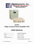
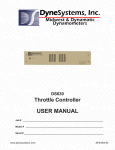
DS820F
Power Amplifier Unit
USER MANUAL
Job # ____________________
www.dynesystems.com
Controller Configuration
Model # __________________
Inter-Loc V Control
Serial # __________________
Dyn-Loc IV Control
Configuration (amps) _______
Customer-Supplied Control, 0-10 VDC
DPD-001-04B
From Dyne Systems, Inc.
The DS820F Power Amplifier Unit (PAU) is a third generation, intelligent universal Eddy Current
Power Amplifier Unit. It is an analog controller with a digital front end that offers greater flexibility for
upgrading existing test cells, or for entirely new test installations. The potential applications for the
PAU range from simple manual control to fully integrated closed loop installations. The PAU interfaces
with all of Dyne Systems’ existing dynamometer controllers, as well as industrial PC/PLC 24 VDC
logic-based controllers running third party software.
The PAU provides a unique set of features:
•
Set up is simple and straightforward.
•
The front panel diagnostic LCD display eliminates guesswork by displaying real time field
current, input command, status and fault messages.
•
System status can also be reported via PLC level I/O to external controls.
•
An analog voltage or current input enables the unit to be used as a standalone open loop eddy
current power amplifier.
•
It can be integrated into existing test cells with fully integrated closed loop control units.
•
The modular construction of the PAU allows it to be interfaced with different dynamometer
control components.
The PAU is available in wall mount or in a space saving and reduced wiring rack mount version. It
also provides significantly increased current capabilities with ratings of 15, 30, 50 and 100 amps at up
to 400 VDC. Higher non-standard current ratings can easily be custom engineered.
For customers who prefer to get leading edge performance and test cell system integration from a
single provider, Dyne Systems’ new PAU fully integrates with Dyne Systems’ dynamometer controls
and eddy current dynamometers.
NOTE: This manual is intended for use by qualified personnel only. All Dyne Systems’ approved
drawings (if included) and specific instructions for this equipment must take precedence over
general information contained in this manual.
Thank you for purchasing this product from Dyne Systems. Our staff is at your disposal, should you
need information or support that is not found in this manual.
CONTROLS, DYNAMOMETERS, SYSTEM INTEGRATION AND TEST CELL AUTOMATION
Dyne Systems, Inc. • W209 N17391 Industrial Drive • Jackson, Wisconsin 53037
phone: 800.657.0726 • website: www.dynesystems.com
Dyne Systems • DS820F PAU
DPD-001-04B • © Copyright Dyne Systems, Inc.
Introduction
1
TABLE OF CONTENTS
SECTION 1:
GENERAL INFORMATION
4
SAFETY...................................................................................................................................4
RECEIVING INSPECTION......................................................................................................4
DAMAGE CLAIMS...................................................................................................................4
TRAINING................................................................................................................................4
IDENTIFY YOUR PAU..............................................................................................................4
SECTION 2:
CONFIGURATION
5
MODES OF RESET OPERATION...........................................................................................8
SECTION 3:
SECTION 4:
INSTALLATION ENVIRONMENT
TRANSFORMER COMPATIBILITY
9
10
WALL MOUNT PAU, COIL AND TRANSFORMER COMPATIBILITY TABLE......................... 10
RACK MOUNT PAU, COIL AND TRANSFORMER COMPATIBILITY TABLE......................... 11
SECTION 5: INSTALLATION AND START UP
12
WHO SHOULD INSTALL THE PAU....................................................................................... 12
WALL MOUNT INSTALLATION.............................................................................................. 12
ENCLOSURE SPECIFICATIONS.......................................................................................... 12
DIMENSIONS........................................................................................................................ 12
WALL MOUNT MECHANICAL INSTALLATION..................................................................... 13
WALL MOUNT WIRING......................................................................................................... 13
WALL MOUNT TERMINAL BLOCK CONNECTIONS............................................................ 14
WALL MOUNT SUBPANEL................................................................................................... 15
WALL MOUNT START-UP..................................................................................................... 16
INTER-LOC V START-UP....................................................................................................... 16
DYN-LOC IV AND CUSTOMER-SUPPLIED CONTROL START-UP...................................... 17
RACK MOUNT INSTALLATION............................................................................................. 18
ENCLOSURE SPECIFICATION . .......................................................................................... 18
DIMENSIONS........................................................................................................................ 18
RACK MOUNT MECHANICAL INSTALLATION..................................................................... 19
RACK MOUNT WIRING......................................................................................................... 19
RACK MOUNT START-UP.....................................................................................................21
INTER-LOC V START-UP.......................................................................................................21
DYN-LOC IV AND CUSTOMER-SUPPLIED CONTROL START-UP......................................22
SECTION 6: PREVENTIVE MAINTENANCE
23
WALL MOUNT.......................................................................................................................23
RACK MOUNT.......................................................................................................................23
2
Dyne Systems • DS820F PAU
DPD-001-04B • © Copyright Dyne Systems, Inc.
Table of Contents
SECTION 7:
APPLICATION SPECIFIC FUNCTIONALITY
24
COMMAND VOLTAGE SCALING...........................................................................................24
CURRENT FEEDBACK.........................................................................................................24
SCALED CURRENT FEEDBACK..........................................................................................24
DYN-LOC IV INTERFACE......................................................................................................24
50HZ / 60HZ OPERATION.....................................................................................................24
LOW INDUCTANCE COIL.....................................................................................................24
LOW MAX CURRENT............................................................................................................24
0-20MA COMMAND SOURCE..............................................................................................24
ADDITIONAL SAFETIES.......................................................................................................25
DS820F CONTROL BOARD JUMPER DEFINITIONS..........................................................25
SECTION 8:
FAULTS / TROUBLESHOOTING
26
WALL MOUNT AND RACK MOUNT TROUBLESHOOTING GUIDE.....................................26
WALL MOUNT SIGNALS.......................................................................................................28
RACK MOUNT SIGNALS......................................................................................................30
SECTION 9:
CUSTOMER SUPPORT 31
SECTION 10:
PRODUCT WARRANTY
32
APPENDIX A:
PAU MAX CURRENT ADJUSTMENT
33
APPENDIX B:
OHM’S LAW
35
APPENDIX C:
DRAWINGS AND SCHEMATICS
36
RACK MOUNT CONNECTIONS - 15 AMP............................................................................36
RACK MOUNT CONNECTIONS - 30 AMP............................................................................37
WALL MOUNT SCHEMATIC.................................................................................................38
APPENDIX D:
CURRENT MODULE REQUIRED CONDUCTOR DEFINITION39
APPENDIX E:
ACRONYMS
Dyne Systems • DS820F PAU
DPD-001-04B • © Copyright Dyne Systems, Inc.
40
Table of Contents
3
SECTION 1:
GENERAL INFORMATION
Within this manual, Dyne Systems, Inc. will be referred to as “DS”.
SAFETY
Read your instruction manual! Electrical rotating equipment can be dangerous. Become
familiar with all safety instructions and procedures. WARNING, CAUTION and NOTE
labels are used throughout the manual to remind you of the hazards that exist. Know your
equipment before handling or working on it.
Used to warn of the possibility of injury to personnel and damage to equipment
Used to caution of the potential hazards and unsafe practices
NOTE: Used for special instructions related to safety, proper operation or maintenance
RECEIVING INSPECTION
Upon the arrival of your equipment, check all items received against the packing slip to
ensure the shipment is complete. Then inspect for damage. Any evidence of rough handling
may be an indication of hidden damage. Be sure to perform the following inspections:
1.
Inspect packaging and skid(s) for any mistreatment. Document and photograph any
signs of damage.
2.
Inspect housing to ensure there is no damage and that unit is intact.
DAMAGE CLAIMS
In the event of damage, report it without delay to the carrier and Dyne Systems. Dyne
Systems’ warranty policy does not cover shipping damage or lost material. It is important
to file a damage claim with the carrier promptly. If you require assistance in settling the
claim, contact Dyne Systems. Refer to equipment by purchase order, model, serial and job
numbers, as shown on the nameplate of the unit involved.
TRAINING
Training programs are an essential part of safe and correct operation. Training provides
the know-how necessary to obtain top performance from your equipment. Dyne Systems
recognizes this fact and offers training classes on-site or at the factory to educate personnel
in safe operating and maintenance procedures.
IDENTIFY YOUR PAU
This PAU was configured at DS for your specific application. The PAU will be physically
configured as either wall mount or rack mount. Review the diagrams and verify your
configuration:
Dyne Systems Inter-Loc V Control (see Figure 2.1 on Page 5).
Dyne Systems Dyn-Loc IV Control (see Figure 2.2 on Page 6).
Customer-Supplied Control: this requires 0-10VDC or 0-20mA Control Signal (see Figure 2.3
on Page 7).
Locate the model and serial numbers on the PAU and verify that they are the same as that
shown on the cover of this manual. This information should be used when contacting DS
customer support.
4
Dyne Systems • DS820F PAU
DPD-001-04B • © Copyright Dyne Systems, Inc.
General Information
CUST xxxVAC
SINGLE PHASE
+ GROUND
DISCONNECT
Dyne Systems • DS820F PAU
DPD-001-04B • © Copyright Dyne Systems, Inc.
Configuration
MIDWEST MW-xxxx
HP xxxxHP ABSORB
RPM xxx/xxx
FIELD xxxV @ xxA
EC DYNAMOMETER
__"x__"x__"
JB
JB
CONDUIT S1*
SPEED/TRQ FB
CONDUIT S3*
H20 SAFETIES FLOW OR PRESSURE OR TEMP
CONDUIT S2*
ECPAU CONTROL
TEST CELL
Digital Multi-Loop Dynamometer and Engine Controller
CA4W COMPUTER
MONITOR
OCS POWER SUPPLY
INTER-LOC V XFMR
INTER-LOC V OCS
INTER-LOC V CONTROL
CONSOLE
7"
5 1/4"
Figure 2.1 - Inter-Loc V Controller Configuration with Wall Mount ECPAU (Optional Rack Mount)
LOAD CELL
JB
20" x 16" x 8"
~40 LBS
ECPAU
xxA
CONDUIT P2*
FACILITY VAC
xxxVAC @ xxA
MAG PU
CONDUIT P5*
EC DYNO FIELD
xxxVDC @ xxA
CONDUIT P4*
ISOLATED VAC
xxxVAC @ xxA
CONDUIT P3*
FACILITY VAC
xxxVAC @ xxA
MINIMUM SPACE OF 12"
ON EITHER SIDE OF ECPAU
FOR COOLING AIR FLOW
TRANSFORMER
T1
FIELD
POWER
-- KVA
--- LBS
--" x --" x --"
CONDUIT P1*
FACILITY VAC
xxxVAC @ xxA
CNTRL XFMR
---/-----KVA
---LBS
-"x-"x-"
DISCONNECT
OPTIONAL(IF 115VAC
NOT AVAILABLE)
INTER-LOC V CONTROL
INTER-LOC V OCS
CONDUIT P7*
FACILITY VAC
xxxVAC @ xxA
CONDUIT P6*
FACILITY VAC
115VAC @ 15A
19"
W209 N17391 Industrial Dr.
Jackson, WI 53037
Fax: 1-262-677-9308
Phone: 1-262-677-9300
www.DyneSystems.com
Inter-Loc V
SECTION 2:
CONFIGURATION
5
CUST xxxVAC
SINGLE PHASE
+ GROUND
6
DISCONNECT
Dyne Systems • DS820F PAU
DPD-001-04B • © Copyright Dyne Systems, Inc.
__"x__"x__"
MIDWEST MW-xxxx
HP xxxxHP ABSORB
RPM xxx/xxx
FIELD xxxV @ xxA
EC DYNAMOMETER
JB
JB
CONDUIT S1*
SPEED/TRQ FB
CONDUIT S3*
H20 SAFETIES FLOW OR PRESSURE OR TEMP
CONDUIT S2*
ECPAU CONTROL
TEST CELL
CA4W COMPUTER
MONITOR
DYN-LOC IV
CONSOLE
Figure 2.2 - Dyn-Loc IV Controller Configuration with Wall Mount ECPAU (Optional Rack Mount)
LOAD CELL
JB
20" x 16" x 8"
~40 LBS
ECPAU
xxA
CONDUIT P2*
FACILITY VAC
xxxVAC @ xxA
MAG PU
CONDUIT P5*
EC DYNO FIELD
xxxVDC @ xxA
CONDUIT P4*
ISOLATED VAC
xxxVAC @ xxA
CONDUIT P3*
FACILITY VAC
xxxVAC @ xxA
MINIMUM SPACE OF 12"
ON EITHER SIDE OF ECPAU
FOR COOLING AIR FLOW
TRANSFORMER
T1
FIELD
POWER
-- KVA
--- LBS
--" x --" x --"
CONDUIT P1*
FACILITY VAC
xxxVAC @ xxA
CONDUIT P6*
FACILITY VAC
115VAC @ 15A
RPM/TORQUE
ACTIVE
LOCK
ACTIVE
TORQUE
CNTRL XFMR
---/-----KVA
---LBS
-"x-"x-"
DISCONNECT
OPTIONAL(IF 115VAC
NOT AVAILABLE)
RPM
DYNLOC
CONDUIT P7*
FACILITY VAC
xxxVAC @ xxA
EMERG
STOP
DYN><LOC
POWER
CONFIGURATION (CONTINUED)
Configuration
CUST xxxVAC
SINGLE PHASE
+ GROUND
DISCONNECT
Dyne Systems • DS820F PAU
DPD-001-04B • © Copyright Dyne Systems, Inc.
Configuration
__"x__"x__"
MIDWEST MW-xxxx
HP xxxxHP ABSORB
RPM xxx/xxx
FIELD xxxV @ xxA
EC DYNAMOMETER
JB
JB
CONDUIT S1*
SPEED/TRQ FB
CONDUIT S3*
H20 SAFETIES FLOW OR PRESSURE OR TEMP
CONDUIT S2*
ECPAU CONTROL
TEST CELL
CUSTOMER SUPPLIED
CONTROLS
CONSOLE
Figure 2.3 - Customer-Supplied Controller, 0-10 VDC or 0-20mA Control Signal with Wall Mount ECPAU (Optional Rack Mount)
LOAD CELL
JB
20" x 16" x 8"
~40 LBS
ECPAU
xxA
CONDUIT P2*
FACILITY VAC
xxxVAC @ xxA
MAG PU
CONDUIT P5*
EC DYNO FIELD
xxxVDC @ xxA
CONDUIT P4*
ISOLATED VAC
xxxVAC @ xxA
CONDUIT P3*
FACILITY VAC
xxxVAC @ xxA
MINIMUM SPACE OF 12"
ON EITHER SIDE OF ECPAU
FOR COOLING AIR FLOW
TRANSFORMER
T1
FIELD
POWER
-- KVA
--- LBS
--" x --" x --"
CONDUIT P1*
FACILITY VAC
xxxVAC @ xxA
CONDUIT P6*
FACILITY VAC
115VAC @ 15A
CONDUIT P7*
FACILITY VAC
xxxVAC @ xxA
CNTRL XFMR
---/-----KVA
---LBS
-"x-"x-"
DISCONNECT
OPTIONAL(IF 115VAC
NOT AVAILABLE)
CONFIGURATION (CONTINUED)
7
MODES OF RESET OPERATION
The PAU has two modes of operation: Reset Required Mode and Automatic Reset Mode.
In the Reset Required Mode, the PAU will require a reset after the application of power or
after a fault condition has occurred. This reset signal is generated by the dynamometer
control system. During a reset condition, a +24 VDC signal is momentarily applied to TB1-6
on the wall mount version, or pin 15 of the 25-pin Dynamometer Control Connector on the
rear of the rack mount version. Reset Required Mode is the default mode of operation when
used in conjunction with an Inter-Loc V controller.
In the Automatic Reset Mode, no reset will be required at power up and the following fault
conditions will self restore: SCR OverTemp, Coolant OverTemp, Low Coolant Pressure/Flow,
Current OverCmd and GP Input Fault X. The Automatic Reset Mode is the default mode of
operation when used in conjunction with a Dyn-Loc IV controller.
xercise caution when using the PAU in the Automatic Reset Mode, as the PAU
E
could unexpectedly apply power to the coil resulting in excessive heating and
possible failure if proper cooling is not supplied.
When a customer-supplied control system is used, Dyne Systems will configure the PAU to
the mode of choice. If the customer does not specify the mode of operation at the time of
order, it will be set to the Reset Required Mode.
8
Dyne Systems • DS820F PAU
DPD-001-04B • © Copyright Dyne Systems, Inc.
Configuration
SECTION 3:
INSTALLATION ENVIRONMENT
The PAU should be mounted so it is not exposed to severe shock and/or vibrations. If adverse
conditions are anticipated, the PAU can be mounted using vibration-damping materials.
The atmosphere should be free of corrosive gases, vapors or particulates that could cause
fire or explosion.
Relative humidity should be 0 to 95% non-condensing.
Temperature range should be 32 to 90° F (0 to 32.2° C).
Dyne Systems • DS820F PAU
DPD-001-04B • © Copyright Dyne Systems, Inc.
Installation Environment
9
SECTION 4:
TRANSFORMER COMPATIBILITY
It is important that the PAU, the Dynamometer Coil, and the Transformer are compatible.
The following tables can be used to check these components in your system.
Wall Mount PAU, Coil and Transformer Compatibility Table
PAU
Transformer
Coil
Wall Mount PAU
Model No.
Current
Specifications
Facility Power
(Primary)
PAU Input Power
(Secondary)
Calculated
Transformer VA
Max. Volts
DC Output
Max. Coil
Current
UEC-PAU-15-W01
15 amp
208
240
3,600
200
15
15 amp
208
277
4,155
250
15
15 amp
240
240
3,600
200
15
15 amp
240
277
4,155
250
15
15 amp
480
240
3,600
200
15
15 amp
480
277
4,155
250
15
UEC-PAU-15-W04
15 amp
208
480
7,200
400
15
UEC-PAU-15-W05
15 amp
240
480
7,200
400
15
UEC-PAU-15-W06
15 amp
480
480
7,200
400
15
UEC-PAU-30-W01
30 amp
208
240
7,200
200
30
UEC-PAU-30-W02
30 amp
240
240
7,200
200
30
30 amp
480
480
14,400
400
30
UEC-PAU-30-W03
30 amp
208
277
8,310
250
30
UEC-PAU-30-W04
30 amp
240
277
8,310
250
30
UEC-PAU-30-W05
30 amp
480
240
7,200
200
30
UEC-PAU-30-W06
30 amp
480
277
8,310
250
30
UEC-PAU-30-W07
30 amp
208
480
14,400
400
30
UEC-PAU-30-W08
30 amp
240
480
14,400
400
30
UEC-PAU-50-W01
50 amp
208
240
12,000
200
50
50 amp
208
277
13,850
250
50
50 amp
240
240
12,000
200
50
50 amp
240
277
13,850
250
50
UEC-PAU-50-W03
50 amp
480
240
12,000
200
50
UEC-PAU-50-W03
50 amp
480
277
13,850
250
50
UEC-PAU-50-W04
50 amp
480
480
24,000
400
50
UEC-PAU-100-W01
100 amp
480
240
24,000
200
100
UEC-PAU-15-W02
UEC-PAU-15-W03
UEC-PAU-50-W02
10
Dyne Systems • DS820F PAU
DPD-001-04B • © Copyright Dyne Systems, Inc.
Transformer Compatibility
RACK MOUNT PAU, COIL AND TRANSFORMER COMPATIBILITY TABLE
PAU
Transformer
Coil
Rack Mount PAU
Model No.
Current
Specifications
Facility Power
(Primary)
PAU Input Power
(Secondary)
Calculated
Transformer VA
Max. Volts DC
Output
Max. Coil
Current
UEC-PAU-15-R01
15 amp
208
240
3,600
200
15
15 amp
208
277
4,155
250
15
15 amp
240
240
3,600
200
15
15 amp
240
277
4,155
250
15
30 amp
208
240
7,200
200
30
30 amp
208
277
8,310
250
30
30 amp
240
240
7,200
200
30
30 amp
240
277
8,310
250
30
UEC-PAU-30-R01
Dyne Systems • DS820F PAU
DPD-001-04B • © Copyright Dyne Systems, Inc.
Transformer Compatibility
11
SECTION 5: INSTALLATION AND START UP
WHO SHOULD INSTALL THE PAU
The DS820F PAU operates as part of a system. If the system is not properly wired,
equipment may be damaged.
Only a qualified licensed electrician should install the DS820F PAU. All
installations should comply with the most current version of the National Electric
Code (NEC) as well as all local codes.
WALL MOUNT INSTALLATION
Enclosure Specifications
The Enclosure for the wall mount PAU meets the following industry standards: UL 50, File
No.E27567 Type I; NEMA/EEMAC Type I; CSA, File No.42184 Type I; IEC 60529, IP30. The
PAU enclosure does not meet oil-tight or dust tight specifications.
Dimensions
8.62 (219)
inches (mm)
8.0
(203)
16.0 (406)
20.0 (508)
Recommended
12” Mounting
Clearance
11.0 (279)
0.31 (8)
1.5 (38)
2.5 (64)
1.06(27)
17.0
(432)
14.5 (368)
12
Dyne Systems • DS820F PAU
DPD-001-04B • © Copyright Dyne Systems, Inc.
17.8
(454)
Figure 5.1 - Dimensions
Installation & Start Up
Wall Mount Mechanical Installation
The PAU should be mounted in the vertical position (Refer to Figure 5.1). It is required that
12” of clearance around the entire PAU be provided to allow for filter changes and adequate
airflow around the cabinet.
The method of mounting the PAU to a vertical surface is the responsibility of the end-user.
Wall Mount Wiring
Once the PAU is securely mounted, and all conduits with the appropriate wires are
in place:
1.
Open the access panel and route the wires into the panel.
2.
Connect the wires according to the prints provided (Refer to Figure 5.2).
Note: The prints provided with the PAU take priority over this manual.
It is likely that not all of the terminal connections will be used.
The PAU has safety inputs in the form of Coolant Temperature and Coolant Pressure/
Flow. Additionally there are three spare generic safety inputs. These inputs have different
functionality and correct wiring must be observed
Note: All digital inputs to and outputs from the PAU terminals are PLC +24VDC logic. The
Current Command (TB1-2 - TB1-3) is an analog signal of 0-10 VDC or 0-20mA. Both single
ended and differential inputs can be configured. The Dyne On command is required to
enable the controller; a dry contact wired between terminals TB1-4 and TB1-5 can be used
in lieu of a PLC or controller.
3.
Close the access door and secure
Dyne Systems • DS820F PAU
DPD-001-04B • © Copyright Dyne Systems, Inc.
Installation & Start Up
13
Wall Mount Terminal Block Connections
Figure 5.2 - Wall-Mount Terminal Block Connection
s
Figure 5.3 - Enlarged view of terminal block
14
Dyne Systems • DS820F PAU
DPD-001-04B • © Copyright Dyne Systems, Inc.
Installation & Start Up
Wall Mount Subpanel
Snubber
Board
SCR Bridge
and
Heatsink
Control
Transformer
Fuses
DS820
Control Board
Current
Transducer
Main
Fuses
Terminal Blocks
Figure 5.4 - Wall Mount Subpanel
Dyne Systems • DS820F PAU
DPD-001-04B • © Copyright Dyne Systems, Inc.
Installation & Start Up
15
WALL MOUNT START-UP
Inter-Loc V Start-Up
1.
Validate that the configuration listed on the cover of the manual, exterior of the unit, and
the sub-panel are identical and appropriate for your application. If these values do not
match or are not appropriate for your application, please contact DS.
2.
Verify the integrity of power wiring (i.e. no shorts to ground, verify coil resistance, etc).
3.
Power up the Inter-Loc V / OCS.
4.
Apply power to the PAU.
5.
The following will appear on the display for ~3 seconds:
Eddy-Current PAU
XX.X A max VX.X
XX.XA - The maximum current of the PAU (15, 30, 50, 100)
VX.X - The version of firmware
The display will then change to the following:
Not Self Res.
Reset Required
Not Self Res. Reset Required - Requires a manual reset after the application of
power or after a fault condition has occurred.
6.
Push the RESET button on the OCS to initiate the system.
7.
The following will appear on the display:
PAU:Ok
0%
Off
0.0A
PAU:Ok - Signifies everything is okay, or else the word Fault is displayed (refer to
Wall Mount Signals Troubleshooting Guide on page 26).
Off - PAU is not enabled
% - Percentage of command signal 0-10 VDC or 0-20mA
A - Amount of current being applied to coil
If Fault is displayed, power down the Inter-Loc V and PAU, correct the fault, and then go
back to Step 3.
16
8.
Perform the Max Current adjustment if this is the first time use. (See Appendix A, p. 32
for setting Max Current.)
9.
Your DS820F PAU is ready for use.
Dyne Systems • DS820F PAU
DPD-001-04B • © Copyright Dyne Systems, Inc.
Installation & Start Up
Dyn-Loc IV and Customer-Supplied Control Start-Up
hen the PAU is powered up in the Automatic Reset Mode the dynamometer
W
could power up in the same state it was in when power was turned off.
1.
Validate that the configuration listed on the cover of the manual, exterior of the unit, and
the sub-panel are identical and appropriate for your application. If these values do not
match or are not appropriate for your application, please contact Dyne Systems.
2.
Verify the integrity of power wiring (i.e. no shorts to ground, verify coil resistance, etc).
3.
Power up the Dyn-Loc IV (or customer controls).
4.
Apply power to the PAU. When power is applied a reset is not required. The following
faults are self-restoring:
• SCR OverTemp
• Current OverCmd
• Coolant OverTemp
• Spare Safeties
• Coolant P/F
The following faults require the power to be turned off and the fault corrected before
reapplying power:
• I Current Err
• Current Reversed
• No Field Current
5.
The following will appear on the display for ~3 seconds:
Eddy-Current PAU
XX.X A max VX.X
XX.XA - The maximum current of the PAU (15, 30, 50, 100)
VX.X - The version of firmware
6.
The following will then appear on the display:
PAU:Ok
Off
0%
0.0A
PAU:Ok - Signifies everything is okay, or else the word Fault is displayed (refer to
Wall Mount Troubleshooting Guide on page 26).
Off - PAU is not enabled
% - Percentage of command signal 0-10VDC or 0-20mA
A - Amount of current being applied to coil
If Fault is displayed, power down the Dyn-Loc IV (or customer controls) and PAU, correct
the fault and go back to Step 3.
7.
Perform the Max Current adjustment if this is the first time use. (See Appendix A, p.32
for setting Max Current.)
8.
Your DS820F PAU is ready for use.
Dyne Systems • DS820F PAU
DPD-001-04B • © Copyright Dyne Systems, Inc.
Installation & Start Up
17
RACK MOUNT INSTALLATION
Enclosure Specification
The DS820F PAU enclosure for the rack style PAU is designed for use in areas which do not
require oil-tight and dust-tight applications. Fans are used to cool the interior. The intake is
at the front of the unit.
Dimensions
Figure 5.5 - Rack Mount Dimensions
18
Dyne Systems • DS820F PAU
DPD-001-04B • © Copyright Dyne Systems, Inc.
Installation & Start Up
Rack Mount Mechanical Installation
The PAU enclosure is designed to install in a standard 19 inch server rack using
supplied rack mount brackets.
The method of securing the rack frame and mounting the PAU in the rack is the
responsibility of the end user.
If access to the back of the unit is available the PAU shall be securely mounted before
any connections are made.
1.
Connect wires according to the 15 Amp wiring diagram (Figure 5.6) or 30 Amp
wiring diagram (Figure 5.7).
2.
When connections are secure, the PAU should be in position and mounted to
the rack.
Rack Mount Wiring
Figure 5.6 - 15 Amp Rack Mount PAU Back Panel Connections
Dyne Systems • DS820F PAU
DPD-001-04B • © Copyright Dyne Systems, Inc.
Installation & Start Up
19
RACK MOUNT WIRING (CONTINUED)
Figure 5.7 - 30 Amp Rack Mount PAU Back Panel Connections
20
Dyne Systems • DS820F PAU
DPD-001-04B • © Copyright Dyne Systems, Inc.
Installation & Start Up
RACK MOUNT START-UP
Inter-Loc V Start-Up
1.
Validate the configuration listed on the cover of the manual and exterior of unit are
identical and appropriate for your application. If these values do not match or are not
appropriate for your application, please contact Dyne Systems.
2.
Verify the integrity of power wiring (i.e. no shorts to ground, verify coil resistance, etc).
3.
Power up the Inter-Loc V / OCS.
4.
Apply power to the PAU.
5.
The following will appear on the display for ~3 seconds:
Eddy-Current
XX.X A max
PAU
VX.X
XX.XA - The maximum current of the PAU (15, 30, 50, 100)
VX.X - The version of firmware
The display will then change to the following:
Not Self Res.
Reset Required
Not Self Res. Reset Required - Requires a manual reset after the application of
power or after a fault condition has occurred.
6.
Push the RESET button on the OCS to Initiate the System.
7.
The following will appear on the display:
PAU: Ok
0%
Off
0.0A
PAU:Ok - signifies everything is okay, or else the word Fault is displayed (refer to
Rack Mount Troubleshooting Guide on page 26).
Off - PAU is not enabled
% - Percentage of command signal 0-10VDC or 0-20mA
A - Amount of current being applied to coil
If Fault is displayed, power down the Inter-Loc V and PAU, correct the fault, and then go
back to Step 3.
8.
Perform the Max Current adjustment if this is the first time use. (See Appendix A, p.32
for setting Max Current.)
9.
Your DS820F PAU is ready for use.
Dyne Systems • DS820F PAU
DPD-001-04B • © Copyright Dyne Systems, Inc.
Installation & Start Up
21
DYN-LOC IV AND CUSTOMER-SUPPLIED CONTROL START-UP
hen the PAU is powered up in the Automatic Reset Mode, the
W
dynamometer could power up in the same state it was in when power was
turned off.
1.
Validate the configuration listed on the cover of the manual and exterior of the unit
are identical and appropriate for your application. If these values do not match or
are not appropriate for your application, please contact Dyne Systems.
2.
Verify the integrity of power wiring (i.e. no shorts to ground, verify coil resistance,
etc).
3.
Power up the Dyn-Loc IV (or customer control).
4.
Apply power to the PAU. When power is applied a reset is not required.
The following faults are self-restoring:
• SCR OverTemp
• Current OverCmd
• Coolant OverTemp
• Spare Safeties
• Coolant P/F
The following faults require the power to be turned off and the fault corrected
before reapplying power:
• I Current Err
• Current Reversed
• No Field Current
5.
The following will appear on the display for ~3 seconds:
Eddy-Current
XX.X A max
PAU
VX.X
XX.XA - The maximum current of the PAU (15, 30, 50, 100)
VX.X - The version of firmware
6.
The following will then appear on the display:
PAU:Ok
0%
Off
0.0A
PAU:Ok - Signifies everything is okay, or else the word Fault is displayed
(Refer to Rack Mount Troubleshooting Guide on page 26).
Off - PAU is not enabled
% - Percentage of command voltage 0-10VDC or 0-20mA
A - Amount of current being applied to coil
If Fault is displayed, power down the Dyn-Loc IV (or customer control) and PAU,
correct the fault, and then go back to Step 3.
22
7.
Perform the Max Current adjustment if this is the first time use. (See Appendix A,
p.32 for setting Max Current.)
8.
Your DS820F PAU is ready for use.
Dyne Systems • DS820F PAU
DPD-001-04B • © Copyright Dyne Systems, Inc.
Installation & Start Up
SECTION 6: PREVENTIVE MAINTENANCE
WALL MOUNT
The only maintenance items on the wall mount PAU are the cabinet air filter elements. It
is recommended that the filter elements be removed, cleaned, and inspected every month.
Use the following procedure to perform the routine maintenance:
1.
De-energize all power source(s) prior to maintaining the filter assembly
2.
Grasp the louvered cover and pull to snap open.
3.
Remove filter element.
4.
Wash with mild detergent and warm water.
5.
Allow filter to air dry.
6.
Insert clean filter element into the filter body.
7.
Snap louvered cover into place.
8.
Reapply power source(s).
RACK MOUNT
The only maintenance items on the rack mount PAU are the air vents and cooling fan(s). It is
recommended that the air vents and cooling fans(s) be inspected monthly and any dust or
debris be removed.
Dyne Systems • DS820F PAU
DPD-001-04B • © Copyright Dyne Systems, Inc.
Preventive Maintenance
23
SECTION 7:
APPLICATION SPECIFIC FUNCTIONALITY
Command Voltage Scaling
The command voltage input is typically a 0 to +10 VDC signal. Zero and span
adjustments are available to accommodate non-standard input voltages. Use
potentiometer P7 to zero and P8 to span the input command voltage while measuring
at TP23(+) and TP20(-) for 0 and +10 VDC. Install JP12 to enable P7 if zeroing is
needed.
Current Feedback
This feedback signal is a representation of the output current as seen by the current
control loop within the DS820F circuit board. The signal is buffered and is available at
TB15 on the DS820F circuit board.
Note: This signal is used for troubleshooting. Please reference Appendix D for more
information.
Scaled Current Feedback
This scaled signal represents a value proportional to 0-100% (0-10 VDC) of the ECPAU
current limit. This signal is available at TB5 in a Wall Mount version or within the “Dyno
Control” connector in a Rack Mount version if JP13 is installed on the DS820F circuit
board.
Dyn-Loc IV Interface
Using the DS820F PAU with a Dyne Systems Dyn-Loc IV controller requires some
unique connections. TB2-1 thru TB2-6 on the wall mount unit and certain pins of the
AUX connector on the rack mount are available for some of the Dyn-Loc IV specific
signals. Jumper JP6 needs to be in POS B and the command input set for differential
mode. This mode of operation is normally configured at the factory.
50Hz / 60Hz Operation
Jumper JP14 allows the DS820F to be configured for either 50Hz or 60Hz operation.
Do not move this jumper without first contacting Dyne Systems.
Low Inductance Coil
Jumper JP2 should be installed when using a low inductance coil. Low inductance
is indicated by a greater than 20% ripple on the dynamometer waveform (seen on
oscilloscope).
Low Max Current
If the Dynamometer coil rating is less than 25% of the ECPAU rating, install JP7 before
adjusting the current limit potentiometer P3. This ensures correct current regulation in
the Dynamometer by the ECPAU.
0-20mA Command Source
Jumper JP1 allows use of a standard 0-20mA current command signal. Install JP1 to
enable this option.
24
Dyne Systems • DS820F PAU
DPD-001-04B • © Copyright Dyne Systems, Inc.
Application Specific Functionality
Additional Safeties
In addition to the two H2O safeties (Coolant Temp and Coolant P/F) there are three inputs
available for custom safeties or faults. TB3-1 thru TB3-6 provide connections for up to three
dry contacts (closed = OK to run). Opening of these contacts will generate a fault. The LCD
display will show “GP Input Fault 1, 2 or 3”. This message can be customized at the factory if
desired. The DS820F ships with jumpers in these inputs.
Note: Reference Table 7.1 (next page) for all jumper definitions.
DS820F Control Board Jumper Definitions
Jumper
Description
IN = Current Input (0-20mA)
Default Positiion
Installed
OUT
NO (Hanging)
OUT
NO (Hanging)
JP1
OUT = Voltage input (0-10 VDC)
JP2
Low Inductance Coil Jumper
JP3
External Current Command Source = Rack Mount
OUT
NO (Hanging)
JP4
External Current Command Source = Wall Mount
IN
YES
JP5
External Armature Feedback from TB9
OUT
NO (Hanging)
JP6
IL5 / TB12 Dyne On Select
POS A
YES
JP7
Low “Max” Current Jumper
OUT
NO (Hanging)
JP8
Connects power commons
Hardwired
N/A
JP9
Connects power commons
Hardwired
N/A
JP10
Connects power commons
Hardwired
N/A
JP12
Input Voltage Offset
OUT
NO (Hanging)
JP13
Scaled Analog Output Jumper (directs to Pin 8 of CON1)
OUT
NO (Hanging)
JP14
50 / 60Hz Select
POS A
YES
IN = Low Inductance Coil
POS A = IL5, POS B = TB12 (Isolated)
IN = Allows P7 to Zero Input
POS A = 60Hz, POS B = 50Hz
Table 7.1
Dyne Systems • DS820F PAU
DPD-001-04B • © Copyright Dyne Systems, Inc.
Application Specific Functionality
25
SECTION 8:
FAULTS / TROUBLESHOOTING
Only qualified licensed electricians should open the PAU enclosure.
NOTE: T
he Coolant Pressure/Flow safety input has a delay of ~5 seconds in the Reset Required
Mode and is instant in the Automatic Reset Mode.
NOTE: T
he Coolant Temperature Safety input, along with the three Spare Safety inputs are
instant in both Reset Modes.
NOTE: T
he main circuit board for the PAU has two LEDs (see Figure A.1, page 33 DS820F Main Circuit Board). The LED toward the center of the board will pulse
once each second. If the LED is not blinking the circuit board is defective or it is
not getting power.
Please refer to Table 8.1, Troubleshooting Guide (below).
Wall Mount and Rack Mount Troubleshooting Guide
Fault/Problem
No indication of Power. (LCD
display blank, no red LED
activity on DS820F logic board,
fan not running).
Cause
Wall Mount Solution
Rack Mount Solution
No power from mains.
Verify integrity of Facility Mains
Verify integrity of Facility Mains
Check fuse FB1-2 (internal)
Blown fuses.
Check PAU main fuses FC1,
FC2
Check PAU Control Transformer
fuses (FU1, FU2, FU3).
No output current from PAU.
PAU not enabled.
Ensure that there is an enable
signal (+24 VDC) at TB1-5.
Ensure that there is an enable
signal (+24 VDC) at Dyno
Control pin 3.
No current command signal.
Check that a 0-10 VDC or
0-20mA reference is being
applied between TB1-2 (input)
and TB1-3 (common).
Check that a 0-10 VDC or
0-20mA reference is being
applied between Dyno Control
pins 1 (input) and 14 (common)
Allow time for the heat sink to
cool down.
Allow time for the heat sink to
cool down.
Cooling fan not running.
Verify operation of cooling fan
and its connections at TB6-1
and TB6-2.
Verify operation of cooling fan.
Check fan fuse FB1-1 (internal).
The heat sink temperature
switch (NC) is defective or
disconnected.
Verify the operation of the
temperature switch mounted
on the heat sink and its
connections.
Verify the operation of the
temperature switch mounted
on the heat sink and its
connections.
The dynamometer cooling
system temperature has
exceeded the setpoint of the
coolant temperature switch
(closed = safe to run).
Allow system to cool down.
Verify the integrity of the
coolant temperature switch and
its connections to TB4-3 and
TB4-4. If a temperature switch
is not installed, a jumper should
be installed across these
terminals.
Allow system to cool down.
Verify the integrity of the
coolant temperature switch and
its connections to AUX-4 and
AUX-9. If a temperature switch
is not installed, a jumper should
be installed across these
terminals.
SCR OverTemp fault showing in The SCR heat sink is too hot.
LCD display.
Coolant OverTemp fault
showing in LCD display.
26
Dyne Systems • DS820F PAU
DPD-001-04B • © Copyright Dyne Systems, Inc.
Faults/Troubleshooting
Fault/Problem
Cause
Wall Mount Solution
Rack Mount Solution
Coolant P/F fault showing in
LCD display.
The dynamometer cooling
system pressure (or flow) has
dropped below the setpoint of
the coolant pressure (or flow)
switch (closed = safe to run).
Verify the operation of the
various components making
up the dyno cooling system.
Check functionality of coolant
pressure (or flow) switch and
its connections to TB4-1 and
TB4-2. If a pressure (or flow)
switch is not installed, a jumper
should be installed across
these terminals.
Verify the operation of the
various components making
up the dyno cooling system.
Check functionality of coolant
pressure (or flow) switch and
its connections to AUX-3 and
AUX-8. If a pressure (or flow)
switch is not installed, a jumper
should be installed across
these terminals.
I Feedback Err fault showing in
the LCD display.
The sensed current flow is
different than the system
expected.
If using a low inductance coil,
try installing jumper JP2.
If using a low inductance coil,
try installing jumper JP2.
Contact Dyne Systems.
Contact Dyne Systems.
Current Reversed fault showing
in LCD display.
Current transducer wiring is
incorrect.
Contact Dyne Systems
Contact Dyne Systems
No Field Current fault showing
in LCD display.
Defective field coil, or wiring to
the field coil.
Verify field coil integrity and its
connections to the PAU at
TB6-3 and TB6-4.
Verify field coil integrity and
its connections to the PAU at
appropriate connector
(see Fig. 5.6 or Fig. 5.7).
Main PAU fuses open.
Not Applicable
Check fuses (FU1, FU2).
Defective field power
transformer
Verify operation of field power
transformer and its connections
to TB6-5, TB6-6, TB6-7 and
TB6-8.
Verify operation of field power
transformer and its connections
at appropriate connector
(see 5.6 or Fig. 5.7).
The applied current command
signal has exceeded 110%.
The nominal current
reference range is 0 to 100%.
Commanded currents of 101%
are allowed indefinitely, 102%
- 109% for approximately 10
seconds, 110% (or greater) are
not allowed.
The nominal current
reference range is 0 to 100%.
Commanded currents of 101%
are allowed indefinitely, 102%
- 109% for approximately 10
seconds, 110% (or greater) are
not allowed.
Current OverCmd fault showing
in LCD display.
Table 8.1 - Wall and Rack Mount Troubleshooting Guide
Dyne Systems • DS820F PAU
DPD-001-04B • © Copyright Dyne Systems, Inc.
Faults/Troubleshooting
27
Faults/Troubleshooting (Continued)
Wall Mount Signals
The PAU Wall Mount Unit uses hard wired terminal block connections to interface to the rest
of the system.
Only qualified licensed electricians should open the PAU enclosure.
A qualified electrician can use the table below to monitor inputs/outputs to aid in diagnosing
problems.
Terminal Connection
TB1-1
Description
+10VDC
Function
Output: +10VDC for Potentiometer option
TB1-2
Command Input
Input: 0-10VDC or 0-20mA command signal
TB1-3
Command Common
Input: Command common
TB1-4
+24VDC
Output: +24VDC for Dyne On and Reset
TB1-5
Dyne On
Input: Enables PAU
TB1-6
Reset
Input: Resets faults / errors
TB1-7
PAU OK
Output: PAU is okay (no faults exist)
TB1-8
P / F OK
Output: Coolant Pressure / Flow is okay
TB1-9
PAU On
Output: PAU is On
TB1-10
Common
Common for the +24VDC
TB2-1
Dyn-Loc Command Input
Input: Command signal form Dyn-Loc
TB2-2
Dyn-Loc Command Common
Input: Command common from Dyn-Loc
TB2-3
Dyn-Loc Dyne On
Input: Enables PAU
TB2-4
Dyn-Loc Dyne On Common
Input: Dyne On common
TB2-5
Dyn-Loc H2O
Output: Dry contact for Dyn-Loc H2O safety
TB2-6
Dyn-Loc H2O
Output: Dry contact for Dyn-Loc H2O safety
TB3-1
+24VDC
Output: +24VDC for Spare Safety 1
TB3-2
Spare Safety 1
Input: Spare Safety 1
TB3-3
+24VDC
Output: +24VDC for Spare Safety 2
TB3-4
Spare Safety 2
Input: Spare Safety 2
TB3-5
+24VDC
Output: +24VDC for Spare Safety 3
TB3-6
Spare Safety 3
Input: Spare Safety 3
TB4-1
+24VDC
Output: +24VDC for coolant pressure/flow switch
TB4-2
Coolant P/F
Input: Coolant pressure/flow switch
TB4-3
+24VDC
Output: +24VDC for coolant temperature switch
TB4-4
Coolant Temp
Input: Coolant temperature switch
TB5-1
Analog Out (+)
Output: Voltage proportional to coil current (0 - 10VDC)
TB5-2
Analog Out (-)
Output: Common
Continued next page
28
Dyne Systems • DS820F PAU
DPD-001-04B • © Copyright Dyne Systems, Inc.
Faults/Troubleshooting
Terminal Connection
Description
Function
TB6-1
Cooling Fan
Output: 120VAC for cabinet cooling fan
TB6-2
Cooling Fan
Output: 120VAC for cabinet cooling fan
TB6-3
Field
Output: Connection to dynamometer coil
TB6-4
Field
Output: Connection to dynamometer coil
TB6-5
AC Input (from secondary)
Input: Connection from secondary side of transformer
TB6-6
AC Input (from secondary)
Input: Connection from secondary side of transformer
TB6-7
AC Output (to primary)
Output: Connection to primary side of transformer
TB6-8
AC Output (to primary)
Output: Connection to primary side of transformer
L1
Main AC Input
Input: Connection to facility main power
L2
Main AC Input
Input: Connection to facility main power
GND
Ground
Input: Connection to facility main ground
Table 8.2 - Faults / Troubleshooting, Wall Mount Signals
Note: For further troubleshooting assistance, please contact Dyne Systems.
Dyne Systems • DS820F PAU
DPD-001-04B • © Copyright Dyne Systems, Inc.
Faults/Troubleshooting
29
Faults/Troubleshooting (Continued)
RACK MOUNT SIGNALS
The DS820F Rack Mount Unit uses D-SUB and MS type connections on the rear panel to
interface to the rest of the system.
A qualified electrician can use the table below to monitor inputs / outputs to aid in diagnosing
problems.
Terminal Connection
Description
Function
Dyno Control-1
Command Input
Input: 0-10 VDC or 0-20mA command signal
Dyno Control-14
Command Common
Input: Command signal common
Dyno Control-2
Command Cable Shield
Shield from Command Input Cable
Dyno Control-11
+24 VDC
Output: +24 VDC for Dyne On and Reset
Dyno Control-3
Dyne On
Input: Enables PAU
Dyno Control-15
Reset
Input: Resets faults / errors
Dyno Control-19
PAU OK
Output: PAU is okay (no faults)
Dyno Control-18
P / F OK
Output: Coolant pressure / flow is okay
Dyno Control-6
PAU On
Output: PAU is ON
Dyno Control-20
Analog Output Common
Output: Common for analog output
Dyno Control-8
Analog Output
Output: Voltage proportional to coil current (0-10VDC)
Dyno Contro-7
Analog Output Shield
Output: Shield for analog output
Dyno Control-23
Common
Common for the +24 VDC
15A
30A
AUX-3
AUX1-3
+24VDC
Output: +24 VDC for coolant pressure / flow switch
AUX-8
AUX1-8
Coolant Pressure / Flow
Input: Coolant pressure / flow switch
AUX-4
AUX1-4
+24VDC
Output: +24VDC for coolant temperature switch
AUX-9
AUX1-9
Coolant Temp
Input: Coolant temperature switch
AUX-1
AUX1-1
+24VDC
Output: +24VDC for Spare Safety 1
AUX-6
AUX1-6
Spare Safety 1
Input: Spare Safety 1
AUX-2
AUX1-2
+24VDC
Output: +24VDC for Spare Safety 2
AUX-7
AUX1-7
Spare Safety 2
Input: Spare Safety 2
AUX-5
AUX1-5
+24VDC
Output: +24VDC for Spare Safety 3
AUX-10
AUX1-10
Spare Safety 3
Input: Spare Safety 3
AUX-11
AUX1-11
Dyn-Loc H2O
Output: Dry contact for Dyn-Loc H2O safety
AUX-12
AUX1-12
Dyn-Loc H2O
Output: Dry contact for Dyn-Loc H2O safety
AUX-14
AUX1-14
Dyn-Loc Dyne On
Input: Enable PAU
AUX-15
AUX1-15
Dyn-Loc Dyne On Common
Input: Dyne On common
Continued next page
30
Dyne Systems • DS820F PAU
DPD-001-04B • © Copyright Dyne Systems, Inc.
Faults/Troubleshooting
Terminal Connection
Description
Function
Power Connections for 15A Rack Mount
ECPAU Power-A
AC Input (Field Power)
Input: Connection from secondary side of transformer
ECPAU Power-B
AC Input (Field Power)
Input: Connection from secondary side of transformer
ECPAU Power-C
Ground
Ground connection for 120VAC
ECPAU Power-D
AC Input (120V Hot)
Input: Connection from secondary side of transformer
ECPAU Power-E
AC Input (120V Neutral)
Input: Connection from secondary side of transformer
ECPAU Power-A
AC Input (Field Power)
Input: Connection from secondary side of transformer
ECPAU Power-B
AC Input (Field Power)
Input: Connection from secondary side of transformer
ECPAU Power-C
Ground
Ground connection for 120VAC
ECPAU Power-D
AC Input (120V Hot)
Input: Connection from secondary side of transformer
ECPAU Power-E
AC Input (120V Neutral)
Power Connections for 30A Rack Mount
Input: Connection from secondary side of transformer
Field Connections for 15A Rack Mount
ECPAU Power-F
Field
Output: Connection to dynamometer coil
ECPAU Power-G
Field
Output: Connection to dynamometer coil
ECPAU Power-H
Ground
Ground connection to dynamometer coil
Field Connections for 30A Rack Mount
Field Power-A
Field
Output: Connection to dynamometer coil
Field Power-B
Field
Output: Connection to dynamometer coil
Field Power-C
Ground
Ground connection to dynamometer coil
Table 8.3 - Faults / Troubleshooting, Rack Mount Signals
Note: For further troubleshooting assistance, please contact Dyne Systems.
SECTION 9:
CUSTOMER SUPPORT
Dyne Systems Customer Support can be reached at 1-800-657-0726 or by
Email at [email protected]. Please have the serial and model numbers available for
all products.
Dyne Systems • DS820F PAU
DPD-001-04B • © Copyright Dyne Systems, Inc.
Troubleshooting - Customer Support
31
SECTION 10: PRODUCT WARRANTY
WARRANTY, REMEDIES AND LIMITATIONS: Dyne Systems, Inc. warrants the following equipment will conform to published
specifications and be free from faulty material or workmanship for the listed time period from date of shipment or onsite repair:
New Controls
Service Calls
Repaired Controls
12 Months
3 Months
3 Months
This warranty covers properly installed equipment used within specified limits and ambient conditions and is limited to repair or
replacement of equipment proving defective at Dyne Systems. For warranty to be valid, Buyer must conform to Dyne Systems’
factory specifications. If applicable, terms of Warranty Validation and Delivery Certification must be met for warranty to be
valid. This warranty does not apply to experimental, developmental or non-standards Goods and Products which are sold “as is”,
“where is”. Dyne Systems shall not be liable for labor costs associated with removing, reinstalling or delivering any equipment.
Transportation costs associated with delivering products to Dyne Systems under the warranty are the responsibility of the Buyer.
Transportation costs associated with returning products to the Buyer under the warranty are the responsibility of Dyne Systems.
If warranty service is deemed necessary and product (i.e. controls, small dynamometer, etc) can be shipped to Dyne Systems
then it is expected that product be sent to Dyne Systems; however, if Buyer wants warranty work to be performed onsite and Dyne
Systems deems it feasible then Buyer will be responsible for travel hours and travel / transportation costs. Dyne Systems is not
liable for costs incurred such as loss of work time or production time or for loss of profits or other damages, including, but not
limited to consequential damage.
THE FOREGOING WARRANTIES ARE EXCLUSIVE AND ARE GIVEN AND ACCEPTED IN LIEU OF ANY AND ALL
OTHER WARRANTIES, EXPRESS OR IMPLIED, INCLUDING WITHOUT LIMITATION, THE IMPLIED WARRANTIES OF
MERCHANTABILITY AND FITNESS FOR A PARTICULAR PURPOSE. THE REMEDIES OF BUYER FOR ANY BREACH OF
WARRANTY SHALL BE LIMITED TO THOSE PROVIDED HEREIN, AND FOR DELAY OR NON-DELIVERY WHICH IS NOT
EXCUSABLE, TO THE PURCHASE PRICE OF THE GOODS IN RESPECT OF WHICH THE DELAY OR NON-DELIVERY IS
CLAIMED, TO THE EXCLUSION OF ANY AND ALL OTHER REMEDIES. IN NO EVENT SHALL DYNE SYSTEMS BE LIABLE
FOR SPECIAL, INDIRECT OR CONSEQUENTIAL DAMAGES, INCLUDING WITHOUT LIMITATION, LOSS OF USE OR
PROFITS. NO AGREEMENT VARYING OR EXTENDING THE FOREGOING WARRANTIES, REMEDIES OR THIS LIMITATION
WILL BE BINDING UPON DYNE SYSTEMS UNLESS IN WRITING SIGNED BY A DULY AUTHORIZED OFFICER OF DYNE
SYSTEMS. DYNE SYSTEMS’ LIABILITY FOR FAILURE TO COMPLY WITH ANY WARRANTY OR REPRESENTATION
HEREUNDER SHALL BE LIMITED TO THE VALUE OF THE GOODS SOLD HEREUNDER.
Excluding equipment made for integrated systems supplied or made by Dyne Systems, Dyne Systems makes no warranty on the
use of the equipment in combination with other products or in the practice of any process and if a claim, suit or action is based
thereon, Buyer shall defend, indemnify and save Dyne Systems harmless therefrom.
LIMITATION OF LIABILITY: Dyne Systems’ liability for defective or nonconforming products, whether based on breach of
warranty negligent manufacture or product liability, is exclusively limited to repair or replacement, at Dyne Systems’ election, of
such products. Dyne Systems assumes no risk and shall be subject to no liability for any damages or loss resulting from the
specific use or application made of the Products. Dyne Systems’ liability for any other claim, whether based on breach of contract,
negligence or product liability, relating to the products shall not exceed the price paid by Buyer for such Products. In no event
will Dyne Systems be liable for any special, incidental or consequential damages, including loss of use, loss of profit, claims of
third parties, or damages arising from bodily injury, or death, however caused, whether by the negligence of Dyne Systems or
otherwise.
EQUIPMENT MADE BY OTHERS: Any items supplied that are not manufactured by Dyne Systems are covered by the original
manufacturer’s warranty and not by a Dyne Systems warranty.
BUYER SUPPLIED PRODUCT: Dyne Systems accepts Buyer provided equipment as a courtesy only. Dyne Systems is not
responsible for determining suitability of Buyer’s equipment for a particular purpose. Repair or configuration of Buyer-supplied
equipment will be charged at Dyne Systems normal rate.
32
Dyne Systems • DS820F PAU
DPD-001-04B • © Copyright Dyne Systems, Inc.
Troubleshooting - Customer Support
APPENDIX A: PAU MAX CURRENT ADJUSTMENT
nly qualified personnel should adjust the PAU Field Current without assistance
O
from Dyne Systems Personnel
Coolant must be flowing during this procedure
All PAUs should be set up for the dynamometer’s “hot amps” current rating.
NOTE: The dynamometer does not need to be spinning during this procedure.
To ensure proper control of the dynamometer and, more importantly, to protect the
coil from damage, the PAU needs to be adjusted to match the characteristics of the
dynamometer coil. The DS820F PAU has a Max Current adjustment potentiometer (P3).
Since dynamometer coil characteristics vary greatly depending on many factors, it is difficult
to preset this adjustment at the factory. It is important that after all connections are made,
the Max Current adjustment be performed.
When first powering on the PAU, the LCD splash screen shows a current value of 15, 30, 50,
or 100 A. This displayed value represents the maximum current that the PAU is capable of
delivering, it does not represent the actual setting of the current limit.
After enabling the PAU, the LCD display will show the field current that is being applied to the
dynamometer. Use this value for making all adjustments.
PAU:Ok
X%
Off
X.XA
PAU:Ok - Signifies everything is okay, or else the word Fault is displayed (refer to
Wall and Rack Mount Troubleshooting Guide, Table 8.1, page 26).
Off - PAU is not enabled
X% - Percentage of command signal (0% = 0VDC or 0mA; 100% = 10VDC or
20mA)
X.XA - Amount of current being applied to coil
The max current setting is preset at the factory to either the minimum setting or an
approximate match to the dynamometer that was specified at the time of sale. In either
case, use the following procedure to check or adjust the max current setting:
1.
Power OFF the PAU.
2.
Turn potentiometer P3 (Figure A-1) on the DS820F board fully counter-clockwise
(minimum field current setting).
3.
Ensure that the dynamometer coolant is flowing and all safeties are met or jumped out.
Dyne Systems • DS820F PAU
DPD-001-04B • © Copyright Dyne Systems, Inc.
Product Warranty
33
APPENDIX A:
PAU MAX CURRENT ADJUSTMENT (CONTINUED)
4.
Power ON the PAU.
5.
Enable the PAU and apply 100% command signal set at +10.0VDC or 20mA.
6.
While enabled, adjust P3 (Max Current Setting) until the desired coil current is reached
(CCW lowers the coil current and CW increases the coil current). The new field current
setting is displayed on the LCD display. Physically measure the coil current as a
precaution. Make sure the measured current closely matches the LCD display.
7.
Disable the PAU.
8.
Connect a DMM to TP20 (black lead) and TP6 (red lead). Adjust P4 until you measure
-0.050VDC (negative 50mV).
9.
Max current setting is complete
LEDs
TP20
P4
P3
TP6
34
Dyne Systems • DS820F PAU
DPD-001-04B • © Copyright Dyne Systems, Inc.
Figure A.1 - DS820F Main Circuit Board
Appendix A - Max Current Adjustment
APPENDIX B: OHM’S LAW
Ohm’s Law defines the relationships between (P) power, (E) voltage, (I) current, and
(R) resistance. One ohm is the resistance value through which one volt will maintain a
current of one ampere.
I (Current) = P (Power) / E (Voltage)
I (Current) = E (Voltage) / R (Resistance)
(I) Current is what flows on a wire or conductor like water flowing down a river. Current flows
from negative to positive on the surface of a conductor. Current is measured in (A) amperes
or amps.
(E) Voltage is the difference in electrical potential between two points in a circuit. It’s the
push or pressure behind current flow through a circuit, and is measured in (V) volts.
(R) Resistance determines how much current will flow through a component. Resistors are
used to control voltage and current levels. A very high resistance allows a small amount of
current to flow. A very low resistance allows a large amount of current to flow. Resistance is
measured in ohms.
(P) Power is the amount of current times the voltage level at a given point measured in
wattage or watts.
Dyne Systems • DS820F PAU
DPD-001-04B • © Copyright Dyne Systems, Inc.
Appendix A - Max Current Adjustment
35
APPENDIX C: DRAWINGS AND SCHEMATICS
RACK MOUNT CONNECTIONS - 15 AMP
Figure C-1 - Rack Mount Connections, 15 Amp
36
Dyne Systems • DS820F PAU
DPD-001-04B • © Copyright Dyne Systems, Inc.
Appendix B - Ohm's Law
RACK MOUNT CONNECTIONS - 30 AMP
Figure C-2 - Rack Mount Connections, 30 AMP
Dyne Systems • DS820F PAU
DPD-001-04B • © Copyright Dyne Systems, Inc.
Appendix C - Drawings & Schematics
37
WALL MOUNT SCHEMATIC
Figure C-3 - Wall Mount Schematic
38
Dyne Systems • DS820F PAU
DPD-001-04B • © Copyright Dyne Systems, Inc.
Appendix C - Drawings & Schematics
APPENDIX D: CURRENT MODULE REQUIRED CONDUCTOR DEFINITION
Conductor Count for 100 Amp LEM Current Module (1000:1)
Feedback Resistor (R36): 50 Ohms
Required Number of Conductors
PAU Max Current Rating
Expected Voltage Across FB Resistor @ Max Current (V)
1
100.00
5.00
2
50.00
5.00
3
33.33
5.00
4
25.00
5.00
5
20.00
5.00
6
16.67
5.00
Conductor Count for 35 Amp LEM Current Module (1000:1)
Feedback Resistor (R36): 150 Ohms
Required Number of Conductors:
PAU Max Current Rating
Expected Voltage Across FB Resistor @ Max Current (V)
1
33.33
5.00
3
11.11
5.00
Dyne Systems • DS820F PAU
DPD-001-04B • © Copyright Dyne Systems, Inc.
Appendix D - Required Conductor Definition
39
APPENDIX E: ACRONYMS
A – Ampere
LCD – Liquid Crystal Display
AC – Alternating Current
LED – Light Emitting Diode
˚C – Degrees Centigrade
NC – Normally Closed Contact
CSA – Canadian Standards Association
NEC – National Electric Code
CW – Clockwise
NEMA – National Electrical Manufacturers
Association
CCW – Counter Clockwise
DC – Direct Current
DUT – Devices under Test
E – Voltage (Volts)
EEMAC – Electrical Equipment Manufacturers
Association of Canada
NO – Normally Open Contact
OCS – Operator Control Station
P – Power (Watts)
PAU – Power Amplifier Unit
PC – Personal Computer
˚F – Degrees Fahrenheit
R – Resistance (Ohms)
FAC – Field AC Power
PLC – Programmable Logic Controller
FU – Fuse
RPM – Revolutions per Minute
GND – Ground
SCR – Silicon-Controller Rectifier
HP – Horse Power
TB – Terminal Block
I – Current (Amps)
UL – Underwriters Laboratory
I/O – Input or Output
V – Voltage (Volts)
IEC – International Electrotechnical Commission
VAC – Volts Alternating Current
JB – Junction Box
VDC – Volts Direct Current
KVA – Kilovolt-Ampere
XFMR – Transformer
KW – Kilowatt
LBS – Pounds
40
Dyne Systems • DS820F PAU
DPD-001-04B • © Copyright Dyne Systems, Inc.
Appendix E - Acronyms


