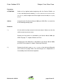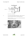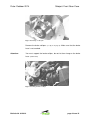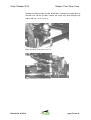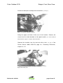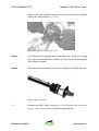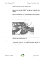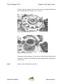
1
Service Bulletin
Bulletin Nr.: 01-2014
Subject: Front gear case differential
Date: October 2014
Model / Model Year:
2008 and 2009
Chassis numbers:
•
4UF#####
Rebuilding range: Within this Service Bulletin the front differential has to be changed on the
Arctic Cat Thundercats mentioned above. Arctic Cat gives you the chance
to increase the value of your Thundercat or the Thundercat of your
costumers from MY 2009 to the current Standards of MY 2010.
Parts order:
1. Front differential gear ratio 3.1 - AC008-472
2. Front differential gear ratio 3.6 - AC008-474
Priority:
Middle
As soon as possible
Bulletin Nr. 01-2014
page 1 from 12
Date: October 2014
Subject: Front Gear Case
Procedure:
ATTENTION:
Switch off the ignition before beginning with the Service Bulletin (Off
Position)
and disconnect the battery (see Service Manual Arctic Cat 2009, PN 2258-
379, page 5-3)
and the engine and exhaust pipe have to be cold (risk of getting
burned).
Advise:
Using the Arctic Cat Service Manual 2009 (p/n 2258-379) is essential for
all the following working steps.
Demount:
1.)
Lift the vehicle to allow removal of the front wheels. Make sure that the
vehicle cannot overturn or move.
Remove the front wheels as described in the Service Manual 2009, p/n
2258-379, page 7-7, chapter “Wheels and Tires“.
Removing the front differential is described in the Service Manual 2009,
p/n 2258-379, on page 6-3, chapter “Removing Differential“.
2.)
Remove the oil drain screw (see Fig. 1 on page 2) from the front differential
case and the fill-up plug. Make sure that the gear oil is disposed of as
instructed by the environmental regulation.
Bulletin Nr. 01-2014
page 2 from 12
Date: October 2014
Subject: Front Gear Case
Oil drain screw
Fig. 1: oil drain screw front differential
3.)
Use the Service Manual 2009, 2258-379, page 7-3, chapter “Front Arms“
and the work specifications below for the following working steps.
Remove the cotter pins (see fig. 3 and 4 on page 4) from the front wheel hub
left and right. Loosen the castle nuts.
Castle nut and cotter
pin
Fig. 2: castle nut with cotter pin
Bulletin Nr. 01-2014
page 3 from 12
Date: October 2014
Subject: Front Gear Case
Fig. 3: Removing of cotter pin
Remove the brake callipers (see fig. 4 on page 4). Make sure that the brake
hose is not cracked.
Attention:
You must support the brake calliper, do not let them hang on the brake
hose. (Strain relief)
Fig. 4: Screwing of Brake Calliper
Bulletin Nr. 01-2014
page 4 from 12
Date: October 2014
Subject: Front Gear Case
Remove the wheel hubs and the brake discs. Remove the cotter pins of
the lock nuts for the tie rods. Loosen the castle nuts and swing the tie
rods aside (Fig. 5 and 6 on page 5).
Fig. 5: Removing of cotter pins for tie rod
Fig. 6: Loosening of screws from tie rod
Bulletin Nr. 01-2014
page 5 from 12
Date: October 2014
Subject: Front Gear Case
Remove the ball joint screwing from the knuckles. (see Fig. 7).
Fig. 7: Loosening the ball joint screwing
Swing the upper and lower A-Arm out of the knuckles. Remove the
screws from the shock absorber on the upper knuckle. (see Service Manual
2009, 2258-379, page 7-2, chapter „Shock Absorber“).
Separate the knuckles from the front axle drive shaft. (see fig. 8). See
Service Manual 2009, 2258-379, page 6-4, “Removing Differential“,
chapter 10 - 13.
Fig. 8: Demounting Axle
Bulletin Nr. 01-2014
page 6 from 12
Date: October 2014
Attention:
Subject: Front Gear Case
Put the front axle drive shaft horizontally to the front differential. Protect
the axle from falling down because a too high angle of the front axle drive
shaft may lead to irreparable damages. Make sure that the upper and
lower A-Arms don’t fall down. Risk of injury and/or damage. Secure the
loosened shock absorbers.
4.)
Remove the fixings of the lower and upper A-Arms and demount them.
Attention:
Two different types of axles must be indentify
1.
Black marked drive axle
2.
White marked drive axle
White marked can not removed with a special tool. To use a slide hammer
can cause to damages
Advise:
You need an Arctic Cat special tool for the following working step to
remove blacked marked axles. “Slide Hammer“ the p/n is 0444-225.
Bulletin Nr. 01-2014
page 7 from 12
Date: October 2014
Subject: Front Gear Case
Remove the front axle drive shaft from the front axle case by using the
special tool “Slide Hammer”. (see fig. 9).
Fig. 9: Demounting the front axle drive shaft
Advise:
Pay attention on the right position of the special tool. Using it in a wrong
way may cause damage to the vehicle itself, the axle, the front differential
case and the axle boot.
Advise:
To remove white marked axles do not use the special tool Slide Hammer.
Fig. 9.1.: White marked axle
5.)
Demount the 2WD / 4WD switch unit (see Service Manual 2009, p/n 2258-379,
page 6-5, chapter 17 and following).
Bulletin Nr. 01-2014
Disconnect the connectors.
page 8 from 12
Date: October 2014
Subject: Front Gear Case
Remove the aeration of the front differential case.
Loosen and remove the holding screws from the front differential case.
Make sure that the front differential case does not fall onto the lower
crossbar.
Move the front differential case forwards towards the radiator assembly.
You can now remove it sideways from the short axle drive shaft between
engine and front differential.
Turn the front differential case by 90° (see fig. 10).
Fig. 10: Demounting Front Gear Case
6.)
Replace the removed front differential (Front Gear Case ASSY) with the front
differential from the Service Bulletin kit.
Advise:
Use
the
Service
Manual
2009,
2258-379,
section
6,
chapter
“Disassembling Pinion Gear“ and the work specifications below for the
following working steps.
Bulletin Nr. 01-2014
page 9 from 12
Date: October 2014
Subject: Front Gear Case
Using a T-40 trox wrench. remove the cap screws securing the differential
cover. Account for an O-Ring (see fig. 11 and fig. 12).
Fig. 11: Open differential case
Fig. 12: Removing splined coupler
Remove the splined coupler, shifter fork, pin and spring of the differential
look ASSY. Remove the left differential bearing flange ASSY and account
for the shim
Note:
Mark all shims with position and side.
Bulletin Nr. 01-2014
page 10 from 12
Date: October 2014
Subject: Front Gear Case
Remove the differential from housing. Account for shim. Place the new
Service Bulletin differential with correct shim in the housing.
Note:
Changed front gear case differentials must be send back for warranty
credit note.
7.)
Start to mount the parts in reversed order.
For the correct shimming please follow the instruction chapter 6,
"Shimming Procedure".
8.)
Please use the torques from the Service Manual 2009, p/n 2258-379.
9.)
Fill the front differential with the front differential oil supplied by Arctic Cat
to the filling level (as required) after assembling (see Service Manual 2009, p/n
2258-379, pages 1-2, pages 2-10).
warning
Please only use original Arctic Cat spare parts/fixings for the assembling. Always use
undamaged / not deformed securing pins for the securing screwing, which should be correct
to the designated borehole and fitting length. For mounting the brake callipers use new
screws and “Loctite” for securing them. Pay attention to the existence of screw securing
means when using new screws.
Advise:
Note the Service Bulletin in the service booklet of the ATV.
Bulletin Nr. 01-2014
page 11 from 12
Date: October 2014
Refund:
Subject: Front Gear Case
After execution of this work, please send a warranty claim containing a
working time of 153 minutes (ATVH1CT07 single cylinder and / or ATVH2CT07 for
H2 engine)
and the p/n of the conversion kit. Please submit a separate
claim for each repaired vehicle.
ATTENTION:
Only completely filled out warranty claims can be accepted.
If you do not send back the old parts, we won’t accept the warranty claim.
Submit the warranty claim and the parts within 30 days after completion of
the service bulletin to Arctic Cat. Warranty Claims which are submitted
later will be rejected.
Advise
The dealer is responsible for assuring that the necessary service for all concerned ATVs is
accomplished according to the instructions which are enclosed in this message. This service must be
accomplished before handing out a concerned ATV to a customer.
Bulletin Nr. 01-2014
page 12 from 12