1
Manual
on the
TroxNetCom-Basic-User-Software
for fire dampers and smoke detectors
Variant 3 (Profibus DP)
System TroxNetCom / AS-interface
for AS-i ControllerE
TNC-A1305/06
written by:
Martin Kluge
KIE-me/Manual_TNCBUS_V3_44-e
Last updated: 04.09.06
page: 1 of 73
Introduction ............................................................................................................... 6
1
Module types...................................................................................................... 7
1.1 Fire damper with one mechanical limit switch .................................................. 7
1.2 Fire damper with two mechanical limit switches ............................................... 8
1.3 Fire damper with inductive dual sensor to detect both end positions ............... 9
1.4 Fire damper with spring-return actuator ......................................................... 10
1.5 RM-O-VS-D smoke detector .......................................................................... 11
1.6 Signal contacts and control signals ................................................................ 12
1.6.1 Centralised messages and commands ................................................... 12
1.6.2 Commands and messages for groups .................................................... 13
1.7 Illuminated pushbutton module ...................................................................... 14
2
General system structure................................................................................ 15
2.1 System principle ............................................................................................. 15
2.2 System supply................................................................................................ 16
2.3 Cable length, signal amplification ................................................................... 17
2.4 Further information about the system............................................................. 18
3
Design of a fire damper system...................................................................... 19
3.1 Grouping ........................................................................................................ 19
3.2 Sequence of the module types ....................................................................... 20
3.3 Documentation by Excel list ........................................................................... 20
4
Basic function of the system .......................................................................... 21
4.1 Functionality in case of thermal release ......................................................... 21
4.1.1 AS-EP and AS-EP4 connection .............................................................. 21
4.1.2 AS-E connection ..................................................................................... 22
4.1.3 AS-EM/B connection ............................................................................... 22
4.2 Functionality in case of smoke detection........................................................ 23
4.2.1 Global release of all smoke detectors ..................................................... 23
4.2.2 Individual release of smoke detectors (manual operation) ...................... 23
4.2.3 Release of smoke detectors in groups .................................................... 23
4.3 Functionality in case of a pollution warning .................................................... 23
KIE-me/Manual_TNCBUS_V3_44-e
Last updated: 04.09.06
page: 2 of 73
4.4 Closing and opening of motor-driven fire dampers......................................... 24
4.4.1 Global closing and opening of all motor-driven fire dampers .................. 24
4.4.2 Individual triggering of motor-driven fire dampers (manual operation) .... 24
4.4.3 Closing and opening of motor-driven fire dampers in groups.................. 24
4.4.4 Closing of motor-driven fire dampers by sequential interlocking ............. 25
4.4.5 Closing of motor-driven fire dampers via a network message or command
26
4.5 Maintenance run of motor-driven fire dampers (damper test) ........................ 27
4.5.1 Maintenance run of motor-driven fire dampers for AS-i controllerE devices
27
4.5.2 Maintenance run of motor-driven fire dampers by groups....................... 27
4.5.3 Maintenance run of fire dampers one after the other or simultaneously.. 27
4.5.4 Maintenance run in general..................................................................... 28
4.6 Diagnosis ....................................................................................................... 29
4.6.1 Manipulation............................................................................................ 29
4.6.2 Exceeded timeout ................................................................................... 29
4.7 Deactivation / Ignoring of smoke signals ........................................................ 30
5
Setting options................................................................................................. 31
5.1 AS-EP or AS-EP4 .......................................................................................... 31
5.2 AS-EP with inverted contacts ......................................................................... 31
5.3 Text selection for AS-EP4 .............................................................................. 32
5.4 Sequential interlocking ................................................................................... 32
5.5 Control via a relay contact.............................................................................. 32
5.6 Close faulty damper during the maintenance run........................................... 33
5.7 Maintenance run one after the other or simultaneously ................................. 33
5.8 Manual operation ........................................................................................... 33
5.9 Deactivation / Ignoring of smoke signals ........................................................ 34
5.10
Group A for ventilation systems, group B for smoke detector groups ......... 34
5.11
Activate group B (2nd group assignment)................................................... 34
5.12
Transmission of messages via the network to control motor-driven fire
dampers ................................................................................................................ 35
KIE-me/Manual_TNCBUS_V3_44-e
Last updated: 04.09.06
page: 3 of 73
6
5.13
Ventilation system specific locking in case of network failure ..................... 35
5.14
Network monitoring..................................................................................... 35
5.15
Gateway mode of IO modules .................................................................... 36
5.16
Change standard type of motor-driven damper .......................................... 36
Operating and display panel of the AS-i controllerE (UserMenu) ............... 37
6.1 Standard page of the AS-i controllerE............................................................ 38
6.2 Pushbutton operation of the UserMenu.......................................................... 39
6.3 Brightness / Contrast adjustment ................................................................... 39
6.4 Language selection ........................................................................................ 39
6.5 Main page for menu navigation ...................................................................... 40
6.6 Locking / Safety function ................................................................................ 42
6.7 Message page................................................................................................ 43
6.8 Page for single control ................................................................................... 45
6.9 Page for maintenance run .............................................................................. 47
7
6.10
Page for settings......................................................................................... 49
6.11
Structure of the standard designations ....................................................... 52
6.12
Adaptation of the designations ................................................................... 53
Operation and set-up....................................................................................... 54
7.1 Cable and fuse protection for power supplies ................................................ 55
7.2 Installation and connection of the AS-i slaves ................................................ 55
7.2.1 AS-i flat cable insulation displacement connectors ................................. 55
7.2.2 Cable branching ...................................................................................... 56
7.2.3 AS-i module lower parts .......................................................................... 56
7.2.4 Connection of input/output modules (e.g. TNC-A2258)........................... 58
7.2.5 Opening of motor-driven fire dampers by assigning commands (jumpers)
to the input/output modules................................................................................ 59
7.3 Addressing of the AS-i slaves / modules ........................................................ 60
7.4 Documentation of the system......................................................................... 61
7.5 Linking unused inputs for AS-EP and AS-EP4 ............................................... 62
7.6 Checking of connected slaves........................................................................ 62
7.7 Projection adaptation ..................................................................................... 64
KIE-me/Manual_TNCBUS_V3_44-e
Last updated: 04.09.06
page: 4 of 73
7.8 Start/Stop of the AS-i controllerE program ..................................................... 65
7.9 Settings .......................................................................................................... 66
7.10
Setting the network address ....................................................................... 67
7.11
Network cable ............................................................................................. 68
7.12
Structure of a Profibus DP network ............................................................ 68
7.12.1 PIN connection........................................................................................ 68
7.12.2 Terminating resistors............................................................................... 69
7.12.3 Screen of the network cable.................................................................... 69
8
7.13
Set-up of the DP slave via the GSD file in the DP master .......................... 70
7.14
Settings....................................................................................................... 71
Functional test ................................................................................................. 72
General notes .......................................................................................................... 72
Important note......................................................................................................... 73
KIE-me/Manual_TNCBUS_V3_44-e
Last updated: 04.09.06
page: 5 of 73
Introduction
The TroxNetCom-Basic-User-Software for fire dampers and smoke detectors is used
to cover the most important basic functions in fire damper and ventilation systems.
Variant 3 provides the option to set up large networks of AS-i controllerE devices via
Profibus DP without adapting the software. The number of the AS-i controllerE
devices as DP slaves depends on the performance of the Profibus DP master.
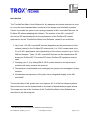
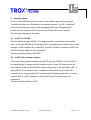
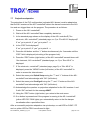
Applications for the TroxNetCom-Basic-User-Software, variant 3 are as follows:
1. Up to max. 126 AS-i controllerE devices (depending on the performance of the
network master) in the Profibus DP network with 1 or 2 AS-i masters and up to
31 or 62 AS-i participants each (depending on the version a total of up to 124 or
248 fire dampers.1) Max. 32 AS-i controllerE devices can be networked as DP
slaves per Profibus DP. For further DP slaves Profibus DP repeaters must be
used.
2. Grouping (see 3.1) by taking RM-O-VS-D smoke detectors and input/output
modules with relay contacts into account
3. Transmission of centralised error messages and group error messages via relay
contacts.
4. Visualisation and operation of the plant via an integrated display of the AS-i
controllerE
The functionality of this system can cover approx. 90 % of the fire damper systems.
Special functions can be implemented on the basis of standardised program blocks.
The scope and use of the functions of the TroxNetCom-Basic-User-Software are
described in the following text.
1
The different types of participants are described in the following text.
KIE-me/Manual_TNCBUS_V3_44-e
Last updated: 04.09.06
page: 6 of 73
1
Module types
In fire damper systems the following connections are possible:
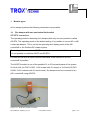
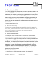
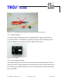
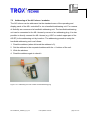
1.1
Fire damper with one mechanical limit switch
AS-EP4 connection
The operating mode for detecting four dampers with only one end position is called
AS-EP4. This operating mode is the default setting. It is possible to use an NC or NO
contact per damper. This is set via the operating and display panel of the AS-i
controllerE or the Profibus DP master system.
The setting is the same for all AS-EP4 modules connected to this AS-i controllerE.
It is not possible to combine AS-EP and AS-EP4.
A combined use with all other modules described in this manual on an AS-i
controllerE is possible.
The AS-EP4 module is one of the possible 31 or 62 bus participants of the system.
So 31x4=124 (for TNC-A1305, 1 AS-i master with 31 slaves) or 2x31x4=248 (TNCA1306, 2 AS-i masters with 31 slaves each ) fire dampers can be connected to an
AS-i controllerE using AS-EP4.
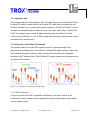
Figure 1.1.1: AS-EP and AS-EP4 connection
KIE-me/Manual_TNCBUS_V3_44-e
Last updated: 04.09.06
page: 7 of 73
1.2
Fire damper with two mechanical limit switches
AS-EP connection
Here the same connection as described in the preceding section is used. However,
two fire dampers with two limit switches each are connected to the module. An
intermediate position of the damper (timeout error due to missing end position) or an
error by actuating both limit switches (manipulation) is detected and evaluated.
The operating mode is called AS-EP and is set via the operating and display panel of
the AS-i controllerE or the Profibus DP master system.
The setting is the same for all AS-EP modules connected to this AS-i controllerE.
It is not possible to combine AS-EP and AS-EP4.
A combined use with all other modules described in this manual on an AS-i
controllerE is possible.
The AS-EP module with the two fire dampers is one of the possible 31 or 62 bus
participants of the system.
So 31x2=62 (for TNC-A1305, 1 AS-i master with 31 slaves) or 2x31x2=124 (TNCA1306, 2 AS-i masters with 31 slaves each ) fire dampers can be connected to an
AS-i controllerE using AS-EP.
KIE-me/Manual_TNCBUS_V3_44-e
Last updated: 04.09.06
page: 8 of 73
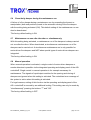
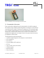
1.3
Fire damper with inductive dual sensor to detect both end positions
AS-E connection
Using the inductive dual sensor both end positions are detected without wear.
The AS-E module is one of the possible 31 or 62 bus participants of the system.
The AS-E module is directly connected to the (yellow) bus cable.
An intermediate position of the damper (timeout error due to missing end position) or
an error by actuating both limit switches (manipulation) or maladjustment is detected
and evaluated.
The AS-E module is a bus participant per damper.
A combined use with all modules described in this manual on an AS-i controllerE is
possible.
Figure 1.3.1: AS-E connection
KIE-me/Manual_TNCBUS_V3_44-e
Last updated: 04.09.06
page: 9 of 73
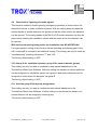
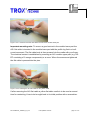
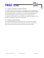
1.4
Fire damper with spring-return actuator
AS-EM/B connection
The spring-return actuator enables a remote actuation of the fire damper. With the
actuator the damper can be opened and closed via remote actuation for test
purposes. Via the AS-EM/B module which is connected to the spring-return actuator
the actuator is triggered and the two end positions are detected. Closing the dampers
can also be triggered by alarm messages (e.g. smoke detector or higher-level
system2 via relay contacts). The evaluation options: incorrect position, timeout
(depending on the direction), error by switching both limit switches (manipulation).
The AS-EM/B module is a bus participant per damper.
A combined use with all modules described in this manual on an AS-i controllerE is
possible.
Figure 1.4.1: AS-EM/B connection
2.
BSA/DDC (Building System Automation/Direct Digital Control)
KIE-me/Manual_TNCBUS_V3_44-e
Last updated: 04.09.06
page: 10 of 73
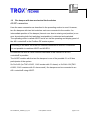
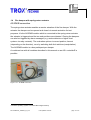
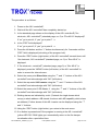
1.5
RM-O-VS-D smoke detector
AS-RM/BD connection
With the AS-RM/BD module a plug-in connection of the corresponding RM-O-VS-D
smoke detector is possible.
The AS-RM/BD module is particularly important as it enables grouping of fire
dampers (see chapter 3.1).
The errors "smoke detected" and "RM-O-VS-D system error" as well as the warning
"pollution of the sensing head >70%" and the message "airflow" are detected. The
test function of the RM-O-VS-D can be triggered with the module.
The AS-RM/BD module supplies the smoke detector with energy and is directly
connected to the bus cable.
The AS-RM/BD module is one bus participant per smoke detector.
A combined use with all modules described in this manual on an AS-i controllerE is
possible.
Figure 1.5.1: AS-RM/B(D) connection
KIE-me/Manual_TNCBUS_V3_44-e
Last updated: 04.09.06
page: 11 of 73
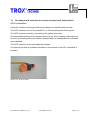
1.6
Signal contacts and control signals
Input/output module connection (e.g. TNC-A2258)
The input/output module is mainly used to receive commands and transmit
messages. Like the module AS-RM/BD the input/output module can be used for
grouping fire dampers (see point 3.1). In addition centralised messages and
commands can be assigned to the input/output module.
The module is a participant of the bus system and has four signal contacts.
1.6.1 Centralised messages and commands
With the slave address 31 centralised error messages of the system are given via
potential-free contacts.
O1:
system ok
O2:
no fire damper CLOSED
O3:
no smoke
O4:
maintenance run not active
With the slave address 31 the following control signals can be transmitted to the
module via potential-free contacts.
I1:
acknowledgement (reset of stored errors)
I2:
opening of all fire dampers
I3:
closing of all fire dampers (priority, NC contact)
I4:
start or stop pulse for the maintenance run (damper test)
KIE-me/Manual_TNCBUS_V3_44-e
Last updated: 04.09.06
page: 12 of 73
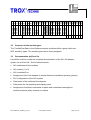
1.6.2 Commands and messages for groups
With the slave addresses 1 .. 30 group error messages of the system are given via
potential-free contacts.
O1:
group OK
O2:
no fire damper in the group CLOSED
O3:
no smoke in the group
O4:
maintenance run of the group not active
With the slave addresses 1 .. 30 the following group control signals can be
transmitted to the module via potential-free contacts.
I1:
acknowledgement (reset of stored errors)
I2:
opening of all fire dampers of the group
I3:
pulse to reset all smoke detectors of the group
I4:
free (not used)
Figure 1.6.2.1: Input/output module with relay contacts
KIE-me/Manual_TNCBUS_V3_44-e
Last updated: 04.09.06
page: 13 of 73
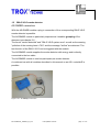
1.7
Illuminated pushbutton module
TNC-A2018 connection
Via light indicators centralised error messages of the system are indicated and the
system can be operated via pushbuttons (e.g. acknowledgement).
Light indicators:
Light indicator green:
system OK, no error
Light indicator red (flashing):
system error (not acknowledged)
Light indicator red (continuously on):
system error (present and
acknowledged)
Pushbutton:
Pushbutton red (pressed > 200 ms):
acknowledgement
(reset of stored errors)
Pushbutton green (pressed > 200 ms):
open all fire dampers
Pushbutton red (pressed > 5s):
close all fire dampers (priority)
Pushbuttons red and green (pressed > 3s) test/reset of the RM-O-VS smoke
sensor
The module is a participant of the bus system.
Figure 1.7.1: Illuminated pushbutton module
KIE-me/Manual_TNCBUS_V3_44-e
Last updated: 04.09.06
page: 14 of 73
2
General system structure
Short description AS-interface
The structure of fire damper systems under the name "TroxNetCom AS-i" is based on
the actuator sensor interface (AS-interface or AS-i).
AS-interface is a manufacturer-independent standard for industry offered by the
companies TROX GmbH and ifm electronic gmbh as wiring and field bus system for
fire damper systems in building system automation.
To reduce installation and set-up cost the ventilation and fire damper components of
TROX GmbH are fitted in the factory with the AS-interface system components from
ifm electronic gmbh.
2.1
System principle
The system is based on the master-slave principle. The modules indicated above
(AS-EP, AS-E, AS-EM/B, AS-RM/BD, etc) which are premounted on the fire dampers
and smoke detectors are distributed in the system. These are the so-called AS-i
slaves. They are connected via a 2-wire profiled yellow cable (AS-i flat cable) with a
wire cross-section of 2 x 1.5 mm² in an open tree structure. An easy and quick
insulation displacement technology – similar to that used in lighting – is applied.
Other cable types, e.g. NYM-J 3x1.5 mm² can also be used but this eliminates the
advantage of the easy insulation displacement technology. Terminating resistors are
NOT required! The max. cable length including all branches is 100 m. To save cable
length the AS-i master controlling the communication with the AS-i slaves should be
installed in direct vicinity of the AS-i slaves in small control cabinets or control boxes.
The so-called AS-i master can be a module/plug-in card of a PLC. To reduce cost the
AS-i master from ifm electronic gmbh is integrated in the AS-i controllerE.
KIE-me/Manual_TNCBUS_V3_44-e
Last updated: 04.09.06
page: 15 of 73
The AS-i controllerE has three tasks or functions:
1. Control of the communication with the AS-i slaves in the field (e.g. AS-EM/B)
2. Interface for coupling with other systems via networks (e.g. operating and control
panel, BSA, DDC, PLC).
3. Integrated programmable PLC functionality
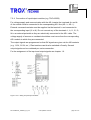
2.2
System supply
To ensure the communication of the AS-i slaves with the AS-i master as well as the
voltage supply of the AS-i slaves via the AS-i flat cable or other cable types one AS-i
power supply per AS-i master must be installed. The AS-i power supply provides the
AS-i voltage (29.5 ... 31.6 V DC) and includes the required data decoupling for
communication. The AS-i power supplies are rated depending on the requirements.
The AS-i controllerE must be supplied with operating voltage via a 24 V DC power
supply.
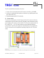
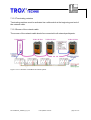
Figure 2.2.1:
Wiring example of an AS-i controllerE with 1 AS-i Master, AS-i power supply and 24 V DC power supply
KIE-me/Manual_TNCBUS_V3_44-e
Last updated: 04.09.06
page: 16 of 73
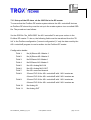
2.3
Cable length, signal amplification
If the cable length of 100 m (total length including all branches of the tree structure) is
not sufficient, it can be extended via a signal amplifier. This signal amplifier is called
AS-i repeater. The AS-i line from the AS-i master is connected to the input (line 1) of
the AS-i repeater. The output of the AS-i repeater (line 2) must be supplied with AS-i
voltage via another AS-i power supply. Another AS-i line of 100 m can now be
connected to this repeater line. If this length is not sufficient either, the first AS-i
repeater can be followed by another repeater. Another length of 100 m is then
available. It is NEVER allowed to use more than 2 AS-i repeaters connected in
series. Further repeaters must be connected again to the master line.
Master and repeater lines must be electrically separated.
Figure 2.3.1: Structure of an AS-i system with AS-i repeaters
KIE-me/Manual_TNCBUS_V3_44-e
Last updated: 04.09.06
page: 17 of 73
2.4
Further information about the system
More details like technical data of the components and graphic representations
concerning the design of fire damper systems with AS-interface are provided in the
system manual "TroxNetCom". It can be obtained on a data carrier from TROX
GmbH or downloaded at www.trox.de.
KIE-me/Manual_TNCBUS_V3_44-e
Last updated: 04.09.06
page: 18 of 73
3
Design of a fire damper system
The electric design of a fire damper system is detailed in the system manual
"TroxNetCom". As the functions of the TroxNetCom-Basic-User-Software are defined
by assigning the AS-i slave addresses, the following definitions apply:
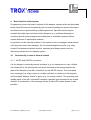
3.1
Grouping
Fire dampers which are used together in a plant or plant section are considered to be
a group if they are assigned to and triggered by one or several smoke detectors or
input/output modules (slave address 1 ... 30).
If no smoke detectors or input/output modules (slave addresses 1 ... 30) are used in
the plant, all fire dampers integrated in the system form one group.
1 to 31 or 62 motor-driven fire dampers or – when AS-EP modules are used for end
position detection – up to 124 or 248 fire dampers can be combined in a group.
Grouping is made by assigning the AS-i slave addresses: Every group begins with
one or several smoke detectors or input/output modules which have the lowest
addresses in the group. A new group can also be formed by one or several
input/output modules, also in combination with smoke detectors, at the lowest slave
addresses within this group. AS-EM/B, AS-E and AS-EP or AS-EP4 then follow in
rising order.
Gaps are allowed in the addressing of the modules AS-EM/B, AS-E and AS-EP or
AS-EP4 of a group if for example installation of bus participants in such a group is
planned at a later point in time.
If a group is to be operated without smoke detectors or/and input/output modules, it
can be formed starting with address 1. This group has the number 0. The end of this
group is defined by the next smoke detector which then starts group 1.
The individual fire dampers connected to AS-EP or AS-EP4 are always assigned
together to one group which depends on the slave assignment.
KIE-me/Manual_TNCBUS_V3_44-e
Last updated: 04.09.06
page: 19 of 73
group 1
AS-EM/B
AS-EM/B
AS-EM/B
AS-EM/B
AS-EM/B
AS-EM/B
AS-EM/B
AS-RM/BD
I/0 module
AS-RM/BD
AS-E
AS-E
AS-EM/B
AS-EM/B
AS-EM/B
AS-EM/B
AS-RM/BD
AS-EM/B
1
2
3
4
5
6
7
8
9
10
11
12
13
14
15
16
17
18
19
20
21
22
23
24
25
26
27
28
29
30
31
AS-EM/B
AS-EM/B
group 0
group 2
Bild 3.1.1: Grouping
3.2
Sequence of the module types
The TroxNetCom-Basic-User-Software expects modules within a group which are
NOT sorted by types. The module types can be freely assigned.
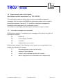
3.3
Documentation by Excel list
It would be useful to create the complete documentation of the AS-i fire damper
system via an Excel list. This list should contain:
•
AS-i addresses of the modules
•
AS-i master (1 or 2)
•
AS-i controllerE no.
•
Assignment of the fire dampers to smoke detectors/ventilation systems (groups)
•
PLC configuration of the AS-i system
•
Data points of the individual fire dampers
•
Data points for the operating and display panel
•
Assignment of external commands to inputs and centralised messages for
external systems (relay contacts) to outputs
KIE-me/Manual_TNCBUS_V3_44-e
Last updated: 04.09.06
page: 20 of 73
4
Basic function of the system
Programming covers the basic functions for fire damper systems which are described
below. Special functions requested by the end user exceeding the scope of the basic
functions can be implemented by qualified personnel. Special functions can for
example be further types of motor-driven dampers (e.g. multileave dampers) or
customer-specific group assignments of dampers to ventilation systems without
smoke detectors or input/output modules.
In general it can be said that a failure in the system or error messages remain stored
until they have been acknowledged. So one acknowledgement option (e.g. relay
contact, illuminated pushbutton module, operating and display panel) must be
definitely provided for a fire damper system.
4.1
Functionality in case of thermal release
4.1.1 AS-EP and AS-EP4 connection
If a fire damper is closed by manual actuation (e.g. for maintenance) or by a fusible
link release (fire), the mechanical limit switch mounted at the damper signals the
state of the damper to the AS-i controllerE via the AS-EP module. The centralised
error message (e.g. relay contact or red light indicator) is switched via the program
and the signal "damper closed" is given (e.g. via a relay contact). The operating and
display panel of the AS-i controllerE indicates a detailed text message for the closed
damper. A visualisation of the message via the Profibus DP master system is also
possible.
KIE-me/Manual_TNCBUS_V3_44-e
Last updated: 04.09.06
page: 21 of 73
4.1.2 AS-E connection
If a fire damper is closed by manual actuation (e.g. for maintenance) or by a fusible
link release (fire), the AS-E module mounted at the damper signals the state of the
damper to the AS-i controllerE. The centralised error message (e.g. relay contact or
red light indicator) is switched via the program and the signal "damper closed" is
given (e.g. via a relay contact). The operating and display panel of the AS-i
controllerE indicates a detailed text message for the closed damper. A visualisation
of the message via the Profibus DP master system is also possible.
4.1.3 AS-EM/B connection
If a fire damper is closed by manual actuation (e.g. for maintenance) or by releasing
the thermo-electric release mechanism (fire), the AS-EM/B module mounted at the
damper signals the state of the damper to the AS-i controllerE. The centralised error
message (e.g. relay contact or red light indicator) is switched via the program and the
signal "damper closed" is given (e.g. via a relay contact). The operating and display
panel of the AS-i controllerE indicates a detailed text message for the closed damper.
A visualisation of the message via the Profibus DP master system is also possible.
KIE-me/Manual_TNCBUS_V3_44-e
Last updated: 04.09.06
page: 22 of 73
4.2
Functionality in case of smoke detection
If smoke is detected by one or several smoke detectors of a group, the assigned
motor-driven fire dampers (AS-EM/B module) are closed. The centralised error
message (e.g. relay contact or red light indicator) is switched via the program and the
signal "smoke" is given (e.g. via a relay contact). The operating and display panel of
the AS-i controllerE indicates a detailed text message for smoke detection. A
visualisation of the message via the Profibus DP master system is also possible.
After smoke detection the system must be acknowledged to delete the stored smoke
signal. Only then can the motor-driven fire dampers be opened again.
4.2.1 Global release of all smoke detectors
If an acknowledgement > 5 s is made by an illuminated pushbutton module, all
smoke detectors can be released at the same time.
The Profibus DP master system also has a key function to release all smoke
detectors.
4.2.2 Individual release of smoke detectors (manual operation)
Smoke detectors can be released individually via the operating and display panel of
the AS-i controllerE or the Profibus DP master system.
4.2.3 Release of smoke detectors in groups
Smoke detectors of a group can be released via a relay contact of an input/output
module. A group-based release via the Profibus DP master system can be set up by
qualified personnel.
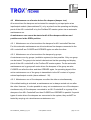
4.3
Functionality in case of a pollution warning
If a pollution warning is given by one or several smoke detectors of a group, the
centralised error message is switched via the program (e.g. relay contact or red light
indicator). The operating and display panel of the AS-i controllerE indicates a detailed
text message for the pollution warning. A visualisation of the message via the
Profibus DP master system is also possible.
KIE-me/Manual_TNCBUS_V3_44-e
Last updated: 04.09.06
page: 23 of 73
4.4
Closing and opening of motor-driven fire dampers
4.4.1 Global closing and opening of all motor-driven fire dampers
All motor-driven fire dampers can be closed via a relay contact or operation via an
illuminated pushbutton module. All motor-driven fire dampers can also be triggered
globally via the Profibus DP master system. If no input/output modules or illuminated
pushbutton modules have been installed, all motor-driven fire dampers are opened
via acknowledgement. At the program start an automatic acknowledgement is given.
4.4.2 Individual triggering of motor-driven fire dampers (manual operation)
Motor-driven fire dampers can be triggered individually via the operating and display
panel of the AS-i controllerE. Triggering via the Profibus DP master system can be
set up by qualified personnel. If the individual operation (manual operation) is
enabled, the sequential interlocking is deactivated during this enable period.
4.4.3 Closing and opening of motor-driven fire dampers in groups
If input/output modules have been set up as modules with group assignment (slave
addresses 1 .. 30), the assigned motor-driven fire dampers (AS-EM/B module) can
be opened by an input signal (signal present) or closed (signal not present). The
centralised error message (e.g. relay contact or red light indicator) is switched via the
program in case of closed fire dampers and the signal "damper closed" is given (e.g.
via a relay contact).
KIE-me/Manual_TNCBUS_V3_44-e
Last updated: 04.09.06
page: 24 of 73
4.4.4 Closing of motor-driven fire dampers by sequential interlocking
If motor-driven fire dampers and other module types are divided in groups via slave
assignment (by smoke detectors or input/output modules) or if all fire dampers are
independent of a group, it is possible to activate a so-called sequential interlocking.
The effect of this sequential interlocking is that if one fire damper of a group closes,
all other motor-driven fire dampers must also close. The type of the "first closing" fire
damper (AS-EP or AS-EP4, AS-E, AS-EM/B) is unimportant. Even if for example a
fire damper with a mechanical limit switch of a group closes, the motor-driven fire
dampers of this group must also close due to the sequential interlocking.
The centralised error message (e.g. relay contact or red light indicator) is switched
via the program in case of closed fire dampers and the signal "damper closed" is
given (e.g. via a relay contact).
Only after acknowledgement of the error message the motor-driven fire dampers
open again.
The sequential interlocking can be set in the TroxNetCom-Basic-User-Software. The
setting is made via the operating and display panel of the AS-i controllerE or the
Profibus DP master system. The default setting is a deactivated sequential
interlocking.
KIE-me/Manual_TNCBUS_V3_44-e
Last updated: 04.09.06
page: 25 of 73
4.4.5 Closing of motor-driven fire dampers via a network message or command
If the AS-i controllerE devices are connected to a Profibus DP master system via a
network, group messages and commands can be exchanged between several
controllerE devices. The following messages or commands can be transmitted via the
network per group (ventilation system):
•
Fire damper CLOSED (as a command for motor-driven fire dampers in case of
sequential interlocking)
•
Smoke signal (as a command for motor-driven fire dampers)
•
Control via a relay contact (as a command for motor-driven fire dampers)
•
Test/reset of smoke detectors (as a command for smoke detectors)
•
Pollution message
•
System error of smoke detectors
•
Timeout error
•
Manipulation / switch error
If commands, e.g. smoke signals, are transmitted via the network to close fire
dampers connected to other AS-i controllerE devices, the correct function of the
network is monitored for reasons of safety. In case of a network failure the motordriven fire dampers are brought to the safety position (CLOSED). The parameters for
transmitting the group messages and commands are set in the Profibus DP master
system.
The default setting is a deactivated transmission of the group messages and
commands.
KIE-me/Manual_TNCBUS_V3_44-e
Last updated: 04.09.06
page: 26 of 73
4.5
Maintenance run of motor-driven fire dampers (damper test)
All motor-driven fire dampers can be tested for example by an input pulse at an
input/output module (slave address 31) or by a pulse from the operating and display
panel of the AS-i controllerE or by the Profibus DP master system via an automatic
maintenance run.
A maintenance run cannot be started until all fire dampers with two end
positions are in the OPEN position.
4.5.1 Maintenance run of motor-driven fire dampers for AS-i controllerE devices
For this automatic maintenance run all motor-driven fire dampers connected to the
AS-i controllerE are CLOSED and OPENED again one after the other.
4.5.2 Maintenance run of motor-driven fire dampers by groups
A maintenance run by groups (ventilation systems) is also possible. Only one group
can be tested. The group to be tested is determined via the operating and display
panel of the AS-i controllerE or the Profibus DP master system. For the automatic
maintenance run by groups all motor-driven fire dampers of the group are also
CLOSED one after the other and then OPENED again. An operating signal of the
active maintenance run of the group is transmitted via the NC contact of a grouprelated input/output module (slave address 1..30).
4.5.3 Maintenance run of fire dampers one after the other or simultaneously
If the default setting is activated, a maintenance run is always carried out one after
the other. However, it is also possible to carry out a maintenance run of fire dampers
simultaneously. All fire dampers connected to an AS-i ControllerE or a group of fire
dampers of an AS-i ControllerE are then CLOSED and OPENED in parallel. If special
types of motor-driven fire dampers are connected to the system, they canNOT be
tested by carrying out a simultaneous maintenance run.
KIE-me/Manual_TNCBUS_V3_44-e
Last updated: 04.09.06
page: 27 of 73
4.5.4 Maintenance run in general
If during opening or closing of the tested fire dampers a timeout error occurs, this can
be evaluated as an indication of a mechanical failure of the fire dampers by the
operating and display panel of the AS-i controllerE or the Profibus DP master system.
A manipulation or switch error (both end positions are switched) can also be
evaluated as an error during the maintenance run. The errors can be acknowledged
only after the maintenance run has been finished. The maintenance run can be
interrupted by a further input pulse on the input/output module (slave address 31), by
a pulse from the operating and display panel of the AS-i controllerE or by the
Profibus DP master system. An operating signal of the active maintenance run is
transmitted via the NC contact of the input/output module (slave address 31).
With the default setting a failure of a fire damper during the maintenance run
leads to an automatic closing of the fire damper. Checking the faulty fire
damper on site is thus absolutely necessary!
This default setting of the maintenance run can also be deactivated. The setting is
made via the operating and display panel of the AS-i controllerE or the Profibus DP
master system.
KIE-me/Manual_TNCBUS_V3_44-e
Last updated: 04.09.06
page: 28 of 73
4.6
Diagnosis
The connections AS-EP (2 fire dampers with 2 end positions each), AS-E, AS-EM/B
provide the option for an enhanced diagnosis due to their 2 end positions. The
diagnostic options are as follows.
4.6.1 Manipulation
Manipulation or switch error means that both limit switches (AS-EP, AS-EM/B) are
actuated or both end positions of the inductive sensor (AS-E) are damped. Normally
only one end position is allowed to be signalled. The manipulation can be monitored
via the program and transmitted as an error message (centralised error message).
The operating and display panel of the AS-i controllerE indicates a detailed text
message for the manipulation. A visualisation of the message via the Profibus DP
master system is also possible.
4.6.2 Exceeded timeout
It is possible that the timeout of the fire damper is too long, e.g. due to mechanical
wear of a fire damper or voltage drops on the cables. This can be monitored via the
program and transmitted as an error message (centralised error message). For
motor-driven fire dampers the timeout for opening and closing the fire dampers is
different (opening: 180 s, closing: 25 s). The operating and display panel of the AS-i
controllerE indicates a detailed text message for the exceeded timeout. A
visualisation of the message via the Profibus DP master system is also possible.
KIE-me/Manual_TNCBUS_V3_44-e
Last updated: 04.09.06
page: 29 of 73
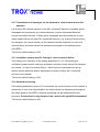
4.7
Deactivation / Ignoring of smoke signals
To set up and clean fire damper systems it is usual to remove the sensing heads of
the RM-O-VS-D smoke detectors. As a result of this, the smoke detectors indicate
smoke and so the assigned motor-driven fire dampers close or cannot open. For setup and cleaning a forced opening (emergency operation) is required to continue the
operation of the ventilation system during this process. This means that in case of a
forced opening the fire dampers are open or in the process of opening and the
signals of the smoke detectors are ignored. As this state does not correspond to the
normal state the centralised error message is given in case of a forced opening. A
forced opening of the fire damper system can be released via a command (relay
contact).
Due to safety regulations forced opening (ignoring of smoke detector signals)
must be set up by a qualified company.
With the forced opening being active the installation has NO APPROVAL!
KIE-me/Manual_TNCBUS_V3_44-e
Last updated: 04.09.06
page: 30 of 73
5
Setting options
The AS-i controllerE devices can be set for the different applications using the
TroxNetCom-Basic-User-Software for fire damper systems. For AS-i controllerE
devices the settings are made via the integrated operating and display panel.
Furthermore the settings can be made via the Profibus DP master system.
The following settings can be made:
5.1
AS-EP or AS-EP4
With this setting the type AS-EP (2 fire dampers with 2 mechanical limit switches
each) or the type AS-EP4 (4 fire dampers with 1 mechanical limit switch each) can be
selected for the complete AS-i controllerE. It is NOT possible to combine AS-EP and
AS-EP4 modules within an AS-i controllerE.
The factory default setting is AS-EP4.
5.2
AS-EP with inverted contacts
This setting distinguishes between type AS-EP and type AS-EP4. If type AS-EP (2
fire dampers with 2 mechanical limit switches each) is used, NC contacts can be
used instead of NO contacts with the setting being active (inverted contacts ON). If
type AS-EP4 (4 fire dampers with 1 mechanical limit switch each) is used, NO
contacts can be used instead of NC contacts with the setting being active (inverted
contacts ON). It is NOT possible to combine NO and NC contacts within an
installation!
The factory default setting is OFF.
KIE-me/Manual_TNCBUS_V3_44-e
Last updated: 04.09.06
page: 31 of 73
5.3
Text selection for AS-EP4
If this setting is activated, the messages “NOT CLOSED” when the fire damper is not
closed and “CLOSED” when the fire damper is closed are indicated on the integrated
display of the AS-i controllerE. This setting can be used when the CLOSED position
is monitored by means of an NC contact. If the OPEN position is monitored by means
of an NO contact, this setting can be deactivated. If this setting is deactivated, the
messages “OPEN” when the fire damper is open and “NOT OPEN” when the fire
damper is not open are indicated on the integrated operating and display panel of the
AS-i controllerE.
The factory default setting is ON.
5.4
Sequential interlocking
The effect of an activated sequential interlocking (ON) is that if a fire damper of a
group closes, all other motor-driven fire dampers of this group must also close. The
motor-driven fire dampers can be opened again by acknowledgement.
The factory default setting is OFF.
5.5
Control via a relay contact
If the setting for control via a relay contact is activated (ON), signals which are
present at the inputs of the group-related input/output modules (slave addresses
1..30) for opening or closing motor-driven fire dampers are directly evaluated. If this
setting is deactivated (OFF), only signals for closing motor-driven fire dampers can
be evaluated. The signals/commands for opening motor-driven fire dampers must be
provided via the central input/output module or via the integrated operating and
display panel of the AS-i controllerE while this setting is deactivated. Signals of
central (slave address 31) or group-related (slave addresses 1 .. 30) input/output
modules have priority over commands of higher-level systems like "open all fire
dampers" or "close all fire dampers".
The factory default setting is:
For the first set-up of installed input/output modules: ON, otherwise OFF
KIE-me/Manual_TNCBUS_V3_44-e
Last updated: 04.09.06
page: 32 of 73
5.6
Close faulty damper during the maintenance run
A failure of a fire damper during a maintenance run by exceeding the timeout or
manipulation (both end positions) leads to the automatic closing of the fire damper
with the setting being activated (ON). This default setting of the maintenance run can
also be deactivated.
The factory default setting is ON.
5.7
Maintenance run one after the other or simultaneously
With this setting being activated, a maintenance run of fire dampers is always carried
out one after the other. When deactivated, a simultaneous maintenance run of fire
dampers can be carried out. A simultaneous maintenance run is only possible for
motor-driven fire dampers and NOT when special types of motor-driven dampers are
integrated.
The factory default setting is ON.
5.8
Manual operation
When manual operation is activated, a single control of motor-driven dampers or
smoke detectors is possible via the integrated operating and display panel of the AS-i
controllerE. Single control in manual operation is for example necessary for
maintenance. The signals of input/output modules for the opening and closing of
dampers are ignored when this setting is activated. The centralised error message of
the system is active when this setting is activated.
For legal reasons, setting of this function via the operating and display panel of the
AS-i controllerE is secured by an additional locking. This setting can only be made by
"simultaneously” pressing the buttons "↑” and "OK”.
The factory default setting is OFF.
KIE-me/Manual_TNCBUS_V3_44-e
Last updated: 04.09.06
page: 33 of 73
5.9
Deactivation / Ignoring of smoke signals
This function enables a forced opening (emergency operation) of motor-driven fire
dampers to set up or clean ventilation systems. With the setting being activated the
smoke signals of smoke detectors are ignored so that the motor-driven fire dampers
can be opened. The sensing heads of the RM-O-VS-D smoke detectors can thus be
removed for cleaning the ventilation system and the motor-driven fire dampers can
be opened.
With the forced opening being active the installation has NO APPROVAL!
For legal reasons, setting of this function via the operating and display panel of the
AS-i controllerE is secured by an additional locking. This setting can only be made by
"simultaneously” pressing the buttons "↑” and "OK”.
The factory default setting is OFF.
5.10 Group A for ventilation systems, group B for smoke detector groups
This setting can only be used in combination with manual adaptations in the
TroxNetCom-Basic-User-Software. With this setting fire dampers or smoke detectors
can be assigned to a ventilation system via a group A and smoke detectors can be
assigned to motor-driven fire dampers via group B.
The factory default setting is OFF.
5.11 Activate group B (2nd group assignment)
This setting can only be used in combination with manual adatations to the
TroxNetCom Basic-User-Software. Via this setting a motor-driven fire damper or a
smoke detector can be assigned a second group.
The factory default setting is OFF.
KIE-me/Manual_TNCBUS_V3_44-e
Last updated: 04.09.06
page: 34 of 73
5.12 Transmission of messages via the network to control motor-driven fire
dampers
If a Profibus DP network superior to the AS-i controllerE devices is installed, group
messages and commands (e.g. smoke detection) can be exchanged between
several controllerE devices. If these group messages and commands are to have
safety-related effects on other AS-i controllerE devices, e.g. closing of motor-driven
fire dampers, the correct function of the network must be monitored. In case of a
network failure the motor-driven fire dampers are brought to the safety position
(CLOSED).
The factory default setting is ON.
5.13 Ventilation system specific locking in case of network failure
This setting is an extension of the setting described in 5.12. If the setting for
ventilation system specific locking is activated, only those motor driven fire dampers
are closed - in case of a network failure - which receive commands from groupspecific smoke detectors and/or input/output modules of other AS-i controllerE
devices in the network.
The factory default setting is ON.
5.14 Network monitoring
If the setting described in point 5.12 is activated, the correct function of the network is
monitored. In case of a network failure the motor-driven fire dampers are brought to
the safety position (CLOSED). Network monitoring can be deactivated for test
purposes. Deactivation is only allowed to be carried out by qualified companies!
The factory default setting is ON.
KIE-me/Manual_TNCBUS_V3_44-e
Last updated: 04.09.06
page: 35 of 73
5.15 Gateway mode of IO modules
If a network system superior to the AS-i ControllerE is installed, the signals of the IO
modules can be passed through to the higher-level system by the AS-i ControllerE
without signal preprocessing (without automatic grouping, without preassigned inputs
and outputs) in the active gateway mode. The assignment of functions of the inputs
and outputs then has to be carried out via the higher-level system.
The factory default setting is OFF.
5.16 Change standard type of motor-driven damper
The standard type of motor-driven damper is the motor-driven fire damper with ASEM/B AS-i connection. As an alternative, motor-driven smoke extraction dampers
with AS-EM/S AS-i connection can be automatically detected. In general the
performed setting applies to all motor-driven dampers connected to the AS-i
controllerE. The setting of motor-driven smoke extraction dampers can only be used
in combination with manual adaptations in the TroxNetCom-Basic-User-Software.
The factory default setting is ON (AS-EM/B).
KIE-me/Manual_TNCBUS_V3_44-e
Last updated: 04.09.06
page: 36 of 73
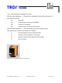
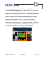
6
Operating and display panel of the AS-i controllerE (UserMenu)
The integrated operating and display panel of the AS-i controllerE is used to display
and operate the connections of the TroxNetCom AS-i system for fire damper systems
described in the preceding chapters. All messages of the individual fire dampers and
smoke detectors can be displayed in detail via the integrated display of the AS-i
controllerE (UserMenu). Stored messages can be acknowledged via the display.
Furthermore, motor-driven fire dampers and smoke detectors can be controlled or
triggered for test purposes via the display. For motor-driven fire dampers a
maintenance run can be initiated via the display. The settings necessary for the
TroxNetCom-Basic-User-Software can also be made via the display. For messages
to be shown via the display of the AS-i controllerE (UserMenu), the program in the
AS-i controllerE must be active (yellow LED PLC RUN permanently lit).
Reset
Figure 6.1: UserMenu display – correct operation
KIE-me/Manual_TNCBUS_V3_44-e
Last updated: 04.09.06
page: 37 of 73
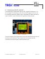
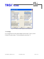
6.1
Standard page of the AS-i controllerE
The standard page is always shown when the AS-i controllerE is switched on. It is
the main page of the internal menu of the AS-i controllerE (page 0). This menu can
be accessed by pressing the “MENU” button. By pressing the “USER” button the socalled “UserMenu” for the TroxNetCom AS-i application can be accessed.
Figure 6.1.1: Standard page
The menu navigation of the internal menu as well as the associated functions are not
described in more detail here. They are presented in the manual of the AS-i
controllerE of ifm electronic gmbh. (www.ifm-electronic.com)
KIE-me/Manual_TNCBUS_V3_44-e
Last updated: 04.09.06
page: 38 of 73
6.2
Pushbutton operation of the UserMenu
The pushbuttons for the control of the display (UserMenu, not in the standard menu)
are programmed so that the next possible message can be shown by briefly pressing
the buttons. If the buttons are pressed longer, the next messages are automatically
displayed one after the other until the buttons are released. So several messages
can be conveniently displayed one after the other and the buttons of the AS-i
controllerE are only subjected to minimum wear.
6.3
Brightness / Contrast adjustment
If the text in the display of the AS-i controllerE (UserMenu) is difficult to read, the
contrast can be adjusted by simultaneously pressing the right button and the “↑“
button (display too bright) or the “↓” button (display too dark).
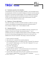
6.4
Language selection
The text in the standard menu and in the UserMenu of the AS-i controllerE can be
displayed in German and in English. By pressing the buttons “↑“ and “↓“
simultaneously, the menu navigation changes between German and English. In order
to protect the selected language against power failure it has to be stored in the
standard menu of the AS-i controllerE. The storage is carried out as follows:
1. Power on the AS-i controllerE.
2. Wait until the AS-i controllerE has completely started up.
3. Is the standard page shown on the display of the AS-i controllerE ("ifm electronic,
AS-i controllerE” (standard page, no. 0) or "Exx AS-iX” displayed)? If “no” go to
point 4, if “yes” go to point 7 à
4. Is the “ESC” field displayed?
If “no” go to point 5, if “yes” go to point 6 à
5. Press the left button and the “↓” button simultaneously for 3 seconds until the
“ESC” field is displayed. (unlocking of the program lock)
6. Press the “ESC” button (right button) of the AS-i controllerE until “ifm electronic,
AS-i controllerE” (standard page, no. 0) or “Exx AS-iX” is displayed.
KIE-me/Manual_TNCBUS_V3_44-e
Last updated: 04.09.06
page: 39 of 73
7. If “ifm electronic, controllerE” (standard page, page 0) or “Exx AS-iX” is displayed,
press the “MENU” button (left button) of the AS-i controllerE in order to access the
internal menu.
8. Select the menu point System Setup using the “↑“ and “↓” buttons of the AS-i
controllerE and acknowledge with “OK” (left button).
9. Select Store System using the “↑“ and “↓” buttons of the AS-i controllerE and
acknowledge with “OK” (left button).
10. Using the “ESC” button (right button) you can return to the main menu.
11. If no button is pressed and if the program is running in the AS-i controllerE (yellow
LED PLC RUN flashes) you automatically return to the fire damper visualisation
after a certain predefined time.
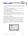
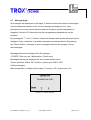
6.5
Main page for menu navigation
Every further page (menu) of the UserMenu can be accessed from this page. You
can scroll through the menu by pressing the buttons “↑“ and “↓“. A page with dark
highlighted text can be selected by pressing the “OK” button. By pressing the “ESC”
button you return to the standard page of the AS-i controllerE. The main page is
automatically loaded by the program several seconds after the program start. If no
button is pressed for a longer time, the message page is automatically loaded (see
chapter 6.7).
Messages
Single control
Maintenance run
OK
↓
ESC
Figure 6.5.1: Menu navigation – top of the list
KIE-me/Manual_TNCBUS_V3_44-e
Last updated: 04.09.06
page: 40 of 73
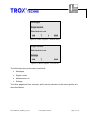
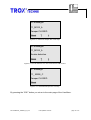
Messages
Single control
Maintenance run
OK
↑
↓
ESC
Figure 6.5.2: Menu navigation – middle of the list
Single control
Maintenance run
Settings
OK
↑
ESC
Figure 6.5.3: Menu navigation – end of the list
The following menu points can be selected:
•
Messages
•
Single control
•
Maintenance run
•
Settings
The other pages and their contents, which can be selected via the menu points, are
described below.
KIE-me/Manual_TNCBUS_V3_44-e
Last updated: 04.09.06
page: 41 of 73
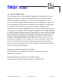
6.6
Locking / Safety function
If no button is pressed on the AS-i controllerE for a longer time, the message page is
automatically loaded. Furthermore, a locking of the display (UserMenu) is activated
and the “ESC” button becomes inactive. By simultaneously pressing the “Reset” and
the “↓” buttons for 3 seconds, the locking can be deactivated. The “ESC” button is
then visible again.
When the display is locked, it is protected against unauthorised manipulation.
System OK
TroxNetCom AS-i
Reset
Figure 6.6.1: Locked display without "ESC" button
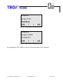
System OK
TroxNetCom AS-i
Reset
ESC
Figure 6.6.2: Unlocked display with "ESC" button
KIE-me/Manual_TNCBUS_V3_44-e
Last updated: 04.09.06
page: 42 of 73
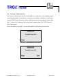
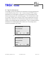
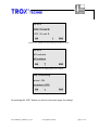
6.7
Message page
All messages are displayed on this page. Furthermore the total amount of messages
and the sequential number of the current message are displayed. For every
participant or for every smoke detector and fire damper a specific designation is
displayed. Section 6.12 describes how the corresponding designations can be
adapted.
By pressing the “↑“ and “↓“ buttons, further fire dampers and smoke detectors can be
displayed. Only a selection of possible messages is presented below. By pressing
the “Reset” button, messages or error messages stored by the program can be
acknowledged.
Messages that can be displayed for fire dampers:
CLOSED, Time out error, Manipulation / Switch error
Messages that can be displayed for duct smoke detectors are:
Smoke detected, Airflow OK, Pollution, System error RM-O-VS-D
Global messages:
Manual operation via higher-level system, Fire alarm, AS-i system error, etc.
System OK
TroxNetCom AS-i
Reset
↑
↓
Figure 6.7.1: Correct operation
KIE-me/Manual_TNCBUS_V3_44-e
Last updated: 04.09.06
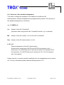
page: 43 of 73
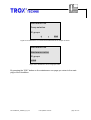
2/4 messages
C1_M1S2_A
Damper CLOSED
Reset
↑
↓
Figure 6.7.2: Closed fire damper with 2 end stops
3/4 messages
C1_M1S5_A
Smoke detection
Reset
↑
↓
Figure 6.7.3: Smoke detection of a duct smoke detector RM-O-VS-D
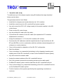
1/1 message
C1_ M2S6_C
Damper CLOSED
Reset
Figure 6.7.4: Closed fire damper with 1 end stop
By pressing the “ESC” button you return to the main page of the UserMenu.
KIE-me/Manual_TNCBUS_V3_44-e
Last updated: 04.09.06
page: 44 of 73
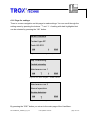
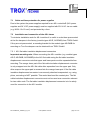
6.8
Page for single control
On this page the status of the individual fire dampers and smoke detectors can be
displayed. Furthermore, motor-driven fire dampers and smoke detectors can be
individually triggered by pressing the “CTRL” button. By pressing the “↑“ and “↓“
buttons, further fire dampers and smoke detectors can be displayed. If a connection
for smoke detectors or motor-driven fire dampers can be triggered, this is indicated
by the visible “CTRL” button. If a motor-driven fire damper is triggered, this is
indicated by means of dark highlighted text (ON). A motor-driven fire damper which is
not triggered is visualised by means of brightly highlighted text (OFF). The system is
in manual operation while the page for single control is active. This means that
the user himself is responsible for opening and closing the motor-driven fire
dampers or testing/triggering the smoke detectors. When this page is left, the
motor-driven fire dampers are moved back to the positions assigned to them by the
program. If smoke detectors have been triggered during single control in manual
operation, the smoke messages must be acknowledged in order to be able to open
the motor-driven fire dampers again.
Messages that can be displayed for fire dampers:
OPEN, CLOSED, NOT CLOSED (or OPEN, NOT OPEN), Time out error,
Manipulation / Switch error
Messages that can be displayed for duct smoke detectors:
Smoke detected, Airflow OK, Pollution, System error RM-O-VS-D
KIE-me/Manual_TNCBUS_V3_44-e
Last updated: 04.09.06
page: 45 of 73
Designation
Damper OPEN
AS-EM/B ON
CTRL
↑
↓
ESC
Figure 6.8.1: Single control of a triggered fire damper
Designation
Damper CLOSED
AS-EM/B OFF
CTRL
↑
↓
ESC
Figure 6.8.2: Single control of an untriggered fire damper
By pressing the “ESC” button you return to the main page of the UserMenu.
KIE-me/Manual_TNCBUS_V3_44-e
Last updated: 04.09.06
page: 46 of 73
6.9
Page for maintenance run
Via this page, a group of fire dampers to be maintained or all groups simultaneously
can be selected by means of the “+” and “-“ buttons. Using the “START” button a
maintenance run can be started. A maintenance run can only be started if all fire
dampers connected to the AS-i controllerE are open. This is indicated by the visible
or non visible “START” button. Using the “STOP” button a maintenance run can be
stopped. If the maintenance run is finished without manual intervention, the display
changes to the message page after a predefined time. There it is indicated whether a
maintenance run has been finished with or without error. This message can be
cancelled by pressing the “ESC” button.
Maintenance run
Group selection
All groups
Start
+
-
ESC
Figure 6.9.1: Maintenance run can be selected for all groups
Maintenance run
Group selection
Group: 2
Start
+
-
ESC
Figure 6.9.2: Maintenance run can be selected for one group
KIE-me/Manual_TNCBUS_V3_44-e
Last updated: 04.09.06
page: 47 of 73
Maintenance run
Group selection
All groups
+
-
ESC
Figure 6.9.3: Maintenance run cannot be activated because fire damper is closed
Maintenance run
Maintenance active
All groups
STOP
Figure 6.9.4: Maintenance run for all groups active
By pressing the “ESC” button on the maintenance run page you return to the main
page of the UserMenu.
KIE-me/Manual_TNCBUS_V3_44-e
Last updated: 04.09.06
page: 48 of 73
6.10 Page for settings
There is a menu navigation on this page to make settings. You can scroll through the
setting menu by pressing the buttons “↑“ and “↓“. A setting with dark highlighted text
can be selected by pressing the “OK” button.
AS-EP / AS-EP4
Contact type EP
Texts AS-EP4
↓
OK
ESC
Figure 6.10.1: Menu navigation – top of the list
Seq. interlocking
Control via relay
Maintenance run 1
OK
↑
↓
ESC
Figure 6.10.2: Menu navigation – middle of the list
Maintenance run 2
Manual operation
Smoke detectors
OK
↑
ESC
Figure 6.10.3: Menu navigation – end of the list
By pressing the “ESC” button you return to the main page of the UserMenu.
KIE-me/Manual_TNCBUS_V3_44-e
Last updated: 04.09.06
page: 49 of 73
The following settings can be made:
•
Module type AS-EP or AS-EP4 (1 or 2 limit switches per fire damper)
•
Contact assignment of AS-EP/AS-EP4 as NC or NO contacts
•
Text selection for AS-EP4: CLOSED, NOT CLOSED or NOT OPEN, OPEN
•
Sequential interlocking ON/OFF
•
Control via a relay contact ON/OFF
•
Maintenance run 1, close or open again the fire damper in case of an error
•
Maintenance run 2, maintain all dampers one after the other or simultaneously
•
Manual operation ON/OFF
•
Activate/deactivate smoke detectors
If a setting is selected using the “OK” button, the current status of the setting is
indicated by means of dark highlighted text. Another setting can be selected using
the “↑“ or “↓“ button. This selection must be acknowledged using the “OK” button.
Exceptions are manual operation and the deactivation of the smoke detectors
(forced opening, ignoring of smoke signals). These can only be activated by
simultaneously pressing the “OK” button and the “↑“ button. The settings can
be deactivated like all other settings. They can be checked by returning to the menu
page for settings by means of the “ESC” button and by reloading the previously
selected menu item. Only some of the possible settings are presented below. The
functions behind these settings are described in detail in chapter 5.
KIE-me/Manual_TNCBUS_V3_44-e
Last updated: 04.09.06
page: 50 of 73
AS-EP4
4 FD / 1 Limit S.
2 FD / 2 Limit S.
↓
OK
ESC
Figure 6.10.4: Selection of the module type AS-EP4 or AS-EP
AS-EP4
NO contacts
NC contacts
OK
↑
ESC
Figure 6.10.5: Setting of NO or NC contacts
Seq. interlocking
active / ON
not active / OFF
OK
↑
ESC
Figure 6.10.6: Setting of sequential interlocking
By pressing the “ESC” button you return to the menu page for settings.
KIE-me/Manual_TNCBUS_V3_44-e
Last updated: 04.09.06
page: 51 of 73
6.11 Structure of the standard designations
To be able to assign the messages in the display to the different AS-i
modules/slaves, standard designations are programmed by default. The structure of
the standard designations is as follows:
e.g. C1_M2S14_A
Cx:
Number of the AS-i ControllerE
(important when using several AS-i ControllerE devices, e.g. in networks)
Mx:
Number of the AS-i master (1 or 2) of the AS-i ControllerE
Sxx: Number of the AS-i slave/module (1 to 31)
A, B, C, D:
Channel designation of the AS-i slave/module
Except for the module types AS-EP and AS-EP4 there always is only 1
channel (A). For AS-EP there are 2 channels (A and B, for 2 dampers with 2
limit switches). For AS-EP4 there are 4 channels (A, B, C, D for 4 dampers
with 1 limit switch).
System-specific or customer-specific modifications to the designations can be carried
out. For more information please read the following section 6.12.
KIE-me/Manual_TNCBUS_V3_44-e
Last updated: 04.09.06
page: 52 of 73
6.12 Adaptation of the designations
The designations for the respective AS-i participants/slaves or for the respective fire
dampers can be freely assigned. This can for example be carried out at the factory to
customer specifications. Furthermore, programming of designations can be made by
a Trox system integrator.
2/3 messages
C1_M2S15_A
Time out error
Reset
↑
↓
Figure 6.12.1: Fire damper message with the standard designation in line 2
2/3 messages
L8 FD E.06
Time out error
Reset
↑
↓
Figure 6.12.2: Fire damper message with a customer-specific designation in line 2
KIE-me/Manual_TNCBUS_V3_44-e
Last updated: 04.09.06
page: 53 of 73
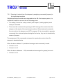
7
Operation and set-up
To enable set-up of a fire damper system using AS-interface the steps described
below must be taken.
The general procedure is as follows:
•
Install the fire dampers and smoke detectors incl. AS-i modules.
•
Install the control boxes for AS-i controllerE and power supplies.
•
Lay and connect the 230 V AC voltage supply for the power supplies in the AS-i
control boxes.
•
Power on the AS-i control boxes.
•
Lay the profiled AS-i cable (AS-i flat cable).
•
Connect the AS-i modules to the AS-i cable (first separate the FC insulation
displacement connectors).
•
Assign the addresses 1 to 31 to the AS-i modules (AS-i slaves).
•
Document the AS-i addresses and the inputs/channels of input modules (for ASEP and AS-EP4) in a list in combination with the ventilation-related designation of
a damper or a smoke detector.
•
Carry out the projection adaptation of the AS-i PLC configuration.
•
Start the software.
•
Carry out settings (e.g. sequential interlocking) via the integrated operating and
display panel of the AS-i controllerE (or later via the Profibus DP master system).
•
Lay and connect the network cable.
•
Assign the network address of the AS-i controllerE devices.
•
Set up the network (activate the terminating resistors at the cable ends!).
•
Profibus DP master system reads the data from the AS-i controllerE devices.
•
Carry out the settings (e.g. sequential interlocking) of the AS-i controllerE devices
via the Profibus DP master system.
•
Test the functions of the system specified by the engineering consultants or
customer.
KIE-me/Manual_TNCBUS_V3_44-e
Last updated: 04.09.06
page: 54 of 73
7.1
Cable and fuse protection for power supplies
Due to the system the power supplies required for an AS-i controllerE (AS-i power
supplies and 24 V DC power supply) must be supplied with 230 V AC via one cable
(e.g. NYM-J 3x1.5 mm²) and protected by a fuse.
7.2
Installation and connection of the AS-i slaves
To minimise installation work for AS-i modules it is useful to order them premounted
at the fire dampers in the factory (module types AS-E, AS-EM/B) from TROX GmbH.
If they are not premounted, a mounting bracket for the module type AS-EM/B for
mounting on Trox fire dampers can be obtained from TROX GmbH.
7.2.1 AS-i flat cable insulation displacement connectors
Important mounting note: When connecting the AS-i modules (e.g. module types
AS-E, AS-EM/B, AS-RM/BD) to the AS-i flat cable using the flat cable insulation
displacement connector note that upper and lower parts must be separated before
mounting. The orange lower part of the flat cable insulation displacement connector
is only snapped onto the AS-i flat cable after separation from the upper part. Only
after snap-on the upper part is screwed into the orange lower part. If the flat cable
insulation displacement connector is erroneously attached unseparated, e.g. using
pliers, contacting is NOT possible. This would also bend the contact pins. The flat
cable insulation displacement connector must not be used as a connection element
for two cable ends. The flat cable insulation displacement connector is to be solely
used for connection to the AS-i module.
KIE-me/Manual_TNCBUS_V3_44-e
Last updated: 04.09.06
page: 55 of 73
Figure 7.2.1.1: AS-i flat cable insulation displacement connector with separated components
7.2.2 Cable branching
As junction box for branching cables a standardised AS-i module lower part with
cover (TNC-A5000 + TNC-A3000), a special AS-i splitter (TNC-70200 when motordriven fire dampers are used) or a common splitter can be used.
Figure 7.2.2.1: AS-i splitter
7.2.3 AS-i module lower parts
AS-i module lower parts can be used as connection elements between the AS-i flat
cable and the AS-i module upper part and as junction box. If the module lower part is
to be used only for cable branching, a cover is mounted instead of the module upper
part (e.g. AS-EP).
KIE-me/Manual_TNCBUS_V3_44-e
Last updated: 04.09.06
page: 56 of 73
Figure 7.2.3.1: Insertion of the AS-i flat cable in the black AS-i module lower part
Important mounting note: To ensure a good contact in the module lower part the
AS-i flat cable is inserted in the module lower part with the profile lug first in a halfround movement. The flat cable back is then pressed into the cradle with your finger.
The electrical contact is established by screwing an AS-i module upper part (e.g. ASEP consisting of 2 orange components) or a cover. When the screws are tightened
the flat cable is pressed into the pins.
Figure 7.2.3.2: Pressing the AS-i flat cable into the yellow cradle
If after removing the AS-i flat cable a yellow flat cable cradle is to be used a second
time for contacting, it has to be brought back to its initial position with a screwdriver.
KIE-me/Manual_TNCBUS_V3_44-e
Last updated: 04.09.06
page: 57 of 73
7.2.4 Connection of input/output modules (e.g. TNC-A2258)
For voltage supply and communication with the AS-i master the terminals A+ and Aof the module must be connected to the corresponding AS-i line (AS-i +, AS-i -).
External command contacts must be supplied via the terminal I+ and connected to
the corresponding input (I1 to I4). Do not connect any of the terminals I-, I+, I1, I2, I3,
I4 to an external potential as they are electrically connected to the AS-i cable. The
voltage supply of sensors or mechanical switches must come from the corresponding
AS-i module to which they are connected.
The output signals are programmed so that OK signals are given via the NO contacts
(e.g. 11/14, 21/24, etc.). Plant sections can thus be switched off easily. Several
output signals can be combined per series connection.
For the assignment of the input and output signals see chapter 1.6.
Figure 7.2.4.1: Wiring of input/output modules
KIE-me/Manual_TNCBUS_V3_44-e
Last updated: 04.09.06
page: 58 of 73
7.2.5 Opening of motor-driven fire dampers by assigning commands (jumpers) to
the input/output modules
If digital input/output modules are integrated into the AS-i fire damper system, it is
imperative to take into account the two following points:
•
The setting "Control via a relay contact" (see chapter 5, setting options) must
always be activated.
•
There must be commands for opening (or NOT closing) of the motor-driven fire
dampers at the inputs of the input/output modules. Without external commands,
the motor-driven fire dampers can NOT be opened. If it is not possible to generate
commands from external systems during the first set-up, they can be simulated by
means of jumpers.
The assignment of the commands or jumpers for opening the motor-driven fire
dampers is described below.
When the slave address 31 (centralised messages and commands) is used:
•
Contact I+ to I2
•
Contact I+ to I3
When the slave addresses 1...30 (commands and messages for groups) are used:
•
Contact I+ to I2
KIE-me/Manual_TNCBUS_V3_44-e
Last updated: 04.09.06
page: 59 of 73
7.3
Addressing of the AS-i slaves / modules
The AS-i slaves can be addressed via the standard menu of the operating and
display panel of the AS-i controllerE or via a handheld addressing unit. For reasons
of flexibility we recommend a handheld addressing unit. The handheld addressing
unit can be connected to the AS-i slaves by means of an addressing plug. It is also
possible to directly connect the AS-i slaves (e.g. AS-E or module upper part of the
AS-EP) to the addressing unit by insertion. The addressing procedure using the
handheld addressing unit is as follows:
1. Read the address (when delivered the address is 0).
2. Set the address to the requested address with the +/- buttons of the unit.
3. Write the address.
4. Read the address again to check it.
Figure 7.3.1: Addressing of an AS-i module via the addressing plug
KIE-me/Manual_TNCBUS_V3_44-e
Last updated: 04.09.06
page: 60 of 73
Figure 7.3.2 Addressing of an AS-i module upper part by direct insertion
7.4
Documentation of the system
Every module which is addressed must be documented in a list with the assigned
AS-i address and the ventilation-related designation of the damper or smoke detector
connected to the AS-i module. Furthermore the assignment of the inputs with regard
to the ventilation-related designation must be documented when using AS-EP (2 fire
dampers with 2 mechanical limit switches each) or AS-EP4 (4 fire dampers with 1
mechanical limit switch each). An example of such a list is given below and can also
be obtained from TROX GmbH.
The following points must be documented:
•
Ventilation-related designation of fire dampers or smoke detectors
•
AS-i controllerE no.
•
AS-i master no.
•
AS-i slave address (AS-i module no.)
•
AS-i line
•
Type of the AS-i slave (AS-i module)
•
Ventilation system
•
Mounting location
•
Note on mounting
KIE-me/Manual_TNCBUS_V3_44-e
Last updated: 04.09.06
page: 61 of 73
7.5
Linking unused inputs for AS-EP and AS-EP4
If for AS-EP modules only one instead of two fire dampers with two end positions is
connected, a jumper must be used for the second channel for the end position OPEN
(jumper between terminal I+ and terminal Ix). The input to be selected depends on
the switch type (NO/NC contacts). If fire dampers with one end position are
connected to AS-EP4 modules, the inputs which are not used for limit switches must
be linked (jumper between terminal I+ and terminal Ix).
7.6
Checking of connected slaves
If all slaves are addressed and connected to the AS-i line, the list of the detected
slaves (LDS) can be indicated via the standard menu of the AS-i controllerE. The
preset and current situation of the AS-i system can thus be easily checked.
KIE-me/Manual_TNCBUS_V3_44-e
Last updated: 04.09.06
page: 62 of 73
The procedure is as follows:
1. Power on the AS-i controllerE.
2. Wait until the AS-i controllerE has completely started up.
3. Is the standard page shown on the display of the AS-i controllerE ("ifm
electronic, AS-i controllerE” (standard page, no. 0) or "Exx AS-iX” displayed)?
If “no” go to point 4, if “yes” go to point 7 -->
4. Is the “ESC” field displayed?
If “no” go to point 5, if “yes” go to point 6 -->
5. Press the left button and the “↓” button simultaneously for 3 seconds until the
“ESC” field is displayed (unlocking of the program lock).
6. Press the “ESC” button (right button) of the AS-i controllerE several times until
“ifm electronic, AS-i controllerE” (standard page, no. 0) or “Exx AS-iX” is
displayed.
7. If “ifm electronic, controllerE” (standard page, page 0) or “Exx AS-iX” is
displayed, press the “MENU” button (left button) of the AS-i controllerE in
order to access the internal menu.
8. Select the menu point Slave lists using the “↑“ and “↓” buttons of the AS-i
controllerE and acknowledge with “OK” (left button).
9. Select the requested AS-i master using the “↑“ and “↓” buttons of the AS-i
controllerE and acknowledge with “OK” (left button).
10. Select the menu point “LDS Master x” using the “↑“ and “↓” buttons of the AS-i
controllerE and acknowledge with “OK” (left button).
11. Existing slaves are indicated by a dot. (S stands for single slaves which
occupy a whole address. A/B stands for slaves with A/B capability which share
an address.) Further slaves of this AS-i master can be displayed using the “↑“
and “↓“ buttons.
12. Using the “ESC” button (right button) you return to the main menu.
13. If no button is pressed and if the program is running in the AS-i controllerE
(yellow LED PLC RUN lights) you automatically return to the fire damper
visualisation after a predefined time.
KIE-me/Manual_TNCBUS_V3_44-e
Last updated: 04.09.06
page: 63 of 73
7.7
Projection adaptation
The projection of the PLC configuration (activated AS-i slaves) must be adapted so
that the AS-i masters of the AS-i controllerE detect the slaves connected to the AS-i
line and can trigger them via the program. The procedure is as follows:
1. Power on the AS-i controllerE.
2. Wait until the AS-i controllerE has completely started up.
3. Is the standard page shown on the display of the AS-i controllerE ("ifm
electronic, AS-i controllerE” (standard page, no. 0) or "Exx AS-iX” displayed)?
If “no” go to point 4, if “yes” go to point 7 -->
4. Is the “ESC” field displayed?
If “no” go to point 5, if “yes” go to point 6 -->
5. Press the left button and the “↓” button simultaneously for 3 seconds until the
“ESC” field is displayed (unlocking of the program lock).
6. Press the “ESC” button (right button) of the AS-i controllerE several times until
“ifm electronic, AS-i controllerE” (standard page, no. 0) or “Exx AS-iX” is
displayed.
7. If “ifm electronic, controllerE” (standard page, page 0) or “Exx AS-iX” is
displayed, press the “MENU” button (left button) of the AS-i controllerE in
order to access the internal menu.
8. Select the menu point Quick Setup using the “↑“ and “↓” buttons of the AS-i
controllerE and acknowledge with “OK” (left button).
9. Select the menu point Config all using the “↑“ and “↓” buttons of the AS-i
controllerE and acknowledge with “OK” (left button).
10. Acknowledge the question on projection adaptation for the AS-i masters 1 and
2 with “OK” and wait for the message WAIT.
11. Using the “ESC” button (right button) you return to the main menu.
12. If no button is pressed and if the program is running in the AS-i controllerE
(yellow LED PLC RUN lights) you automatically return to the fire damper
visualisation after a predefined time.
After a successful projection adaptation via quick setup, no red LED for CONF / PF
and no yellow LED for PROJ are allowed to light.
KIE-me/Manual_TNCBUS_V3_44-e
Last updated: 04.09.06
page: 64 of 73
7.8
Start/Stop of the AS-i controllerE program
To activate or deactivate the program described above the following steps must be
taken:
1. Power on the AS-i controllerE.
2. Wait until the AS-i controllerE has completely started up.
3. Is the standard page shown on the display of the AS-i controllerE ("ifm
electronic, AS-i controllerE” (standard page, no. 0) or "Exx AS-iX” displayed)?
If “no” go to point 4, if “yes” go to point 7 -->
4. Is the “ESC” field displayed?
If “no” go to point 5, if “yes” go to point 6 -->
5. Press the left button and the “↓” button simultaneously for 3 seconds until the
“ESC” field is displayed (unlocking of the program lock).
6. Press the “ESC” button (right button) of the AS-i controllerE several times until
“ifm electronic, AS-i controllerE” (standard page, no. 0) or “Exx AS-iX” is
displayed.
7. If “ifm electronic, controllerE” (standard page, page 0) or “Exx AS-iX” is
displayed, press the “MENU” button (left button) of the AS-i controllerE in
order to access the internal menu.
8. Select the menu point PLC Setup using the “↑“ and “↓” buttons of the AS-i
controllerE and acknowledge with “OK” (left button).
9. Select either Run or Stop using the “↑“ and “↓” buttons of the AS-i controllerE
and acknowledge with “OK” (left button).
10. Using the “ESC” button (right button) you return to the main menu.
11. If no button is pressed and if the program is running in the AS-i controllerE
(yellow LED PLC RUN lights) you automatically return to the fire damper
visualisation after a certain predefined time.
If the yellow LED PLC RUN does not light although the instructions have been
carried out correctly, it must be assumed that no program has been loaded to the
AS -i controllerE or that it has been deleted manually.
KIE-me/Manual_TNCBUS_V3_44-e
Last updated: 04.09.06
page: 65 of 73
7.9
Settings
For a complete set-up of the system settings must be made. To do so, use the
operating and display panel of the AS-i controllerE.
The following settings can be made:
•
Module type AS-EP or AS-EP4 (1 or 2 limit switches per fire damper)
•
Contact assignment of AS-EP/AS-EP4 as NC or NO contacts
•
Text selection for AS-EP4: CLOSED, NOT CLOSED or NOT OPEN, OPEN
•
Sequential interlocking ON/OFF
•
Control via a relay contact ON/OFF
•
Maintenance run 1, close or open again the fire damper in case of an error
•
Maintenance run 2, maintain all dampers one after the other or simultaneously
•
Manual operation ON/OFF
•
Activate/deactivate smoke detector
For further general details concerning the functionalities assigned to the settings see
chapter 5 of this manual.
For further details concerning settings via the UserMenu (operating and display panel
of the AS-i controllerE) please refer to section 6.10 of this manual.
KIE-me/Manual_TNCBUS_V3_44-e
Last updated: 04.09.06
page: 66 of 73
7.10 Setting the network address
If AS-i controllerE devices are used in a Profibus DP network, every AS-i controllerE
must be assigned a network address. Every network address is allowed only once.
Addresses from "003" to "126" can be set. For Profibus DP PLC masters the
addresses "001" and "002" are reserved for the master and the network.
The procedure for setting the network address is as follows:
1. Power on the AS-i controllerE.
2. Wait until the AS-i controllerE has completely started up.
3. Is the standard page shown on the display of the AS-i controllerE ("ifm
electronic, AS-i controllerE” (standard page, no. 0) or "Exx AS-iX” displayed)?
If “no” go to point 4, if “yes” go to point 7 -->
4. Is the “ESC” field displayed?
5. If “no” go to point 5, if “yes” go to point 6 -->
6. Press the left button and the “↓” button simultaneously for 3 seconds until the
“ESC” field is displayed (unlocking of the program lock).
7. Press the “ESC” button (right button) of the AS-i controllerE several times until
“ifm electronic, AS-i controllerE” (standard page, no. 0) or “Exx AS-iX” is
displayed.
8. If “ifm electronic, controllerE” (standard page, page 0) or “Exx AS-iX” is
displayed, press the “MENU” button (left button) of the AS-i controllerE in
order to access the internal menu.
9. Select the menu point Fieldbus Setup using the “↑“ and “↓” buttons of the
AS - i controllerE and acknowledge with “OK” (left button).
10. Select the address using the “↑“ and “↓” buttons of the AS-i controllerE and
acknowledge with “OK” (left button).
11. Using the “ESC” button (right button) you return to the main menu.
12. If no button is pressed and if the program is running in the AS-i controllerE
(yellow LED PLC RUN lights) you automatically return to the fire damper
visualisation after a predefined time.
The network address can also be assigned via the Profibus DP master system.
KIE-me/Manual_TNCBUS_V3_44-e
Last updated: 04.09.06
page: 67 of 73
7.11 Network cable
The network cable for networking the AS-i controllerE devices via Profibus DP with a
Profibus DP master system must be a Profibus DP cable which complies with the
Profibus standard, e.g. concerning the wave resistance. ON NO ACCOUNT must for
example a screened telephone cable be used. The cable type LEONI "L45467-G16C145“ for example can be used. Suitable network plugs are Phoenix Contact,
"Subcon-Plus-Profib/SC art.: 27 44 584" (plugs with terminating resistors that can be
activated and 2 cable entries).
7.12 Structure of a Profibus DP network
The network cable for Profibus DP systems must be "passed through" from
participant to participant (AS-i controllerE or Profibus DP master system). Spurs are
NOT allowed! Laying the network cable via terminals other than the integrated
terminal is NOT allowed either! The Profibus DP master system can be positioned at
any point in the network.
Figure 7.12.1: Structure of a Profibus DP network system
7.12.1 PIN connection
The pins A and B of the AS-i controllerE interfaces or the pins A and B of the
Profibus DP master system must be passed through from participant to participant
via the network plugs.
KIE-me/Manual_TNCBUS_V3_44-e
Last updated: 04.09.06
page: 68 of 73
7.12.2 Terminating resistors
Terminating resistors must be activated via a slide switch at the beginning and end of
the network cable.
7.12.3 Screen of the network cable
The screen of the network cable should be connected to all network participants.
Figure 7.12.3.1: Structure of a Profibus DP network system
KIE-me/Manual_TNCBUS_V3_44-e
Last updated: 04.09.06
page: 69 of 73
7.13 Set-up of the DP slave via the GSD file in the DP master
To ensure that the Profibus DP master system detects the AS-i controllerE devices
as Profibus DP slaves they must be set up in the master system via a so-called GSD
file. The procedure is as follows:
Via the GSD file "ifm_04D8.GSD“ the AS-i controllerE is set up as a slave in the
Profibus DP master. To do so, the following fields must be transferred from the "ID
list" in the Profibus configuration ("current configuration") if only the data used by the
AS-i controllerE program is read or written via the Profibus DP master.
Configuration details:
Field 1:
No (A)Slaves AS-i Master 1
Field 2:
No (A)Slaves AS-i Master 2
Field 3:
No B-Slaves AS-i Master 1
Field 4:
No B-Slaves AS-i Master 2
Field 5:
No AS-i Analog MUX IN
Field 6:
No AS-i Analog MUX OUT
Field 7:
No AS-i command channel
Field 8:
32-word PLC IN for AS-i controllerE with 1 AS-i master or
64-word PLC IN for AS-i controllerE with 2 AS-i masters or
Field 9:
32-word PLC IN for AS-i controllerE with 1 AS-i master or
64-word PLC IN for AS-i controllerE with 2 AS-i masters or
Field 10:
No Analog IN
Field 11:
No Analog OUT
KIE-me/Manual_TNCBUS_V3_44-e
Last updated: 04.09.06
page: 70 of 73
Figure 7.13.1: Profibus DP master configuration window with GSD data
7.14 Settings
For a complete set-up of the system settings must be made. To do so, use the
Profibus DP master system. For the settings also see section 7.9.
KIE-me/Manual_TNCBUS_V3_44-e
Last updated: 04.09.06
page: 71 of 73
8
Functional test
Once all of the steps described above have been completed it is necessary for the
user/commissioning engineer to perform a functional test of the system.
The user/commissioning engineer is personally responsible for the safe and reliable
functioning of the whole system.
Please ensure you have read and observe the important note given at the end of this
manual.
General notes
The TroxNetCom Basic-User-Software user manuals are detailed training manuals
and may be used as operating instructions.
Technical support and instruction by telephone for the TroxNetCom Basic-UserSoftware is therefore not provided free of charge.
We reserve the right to make technical alterations without prior notice!
No manual can be entirely free of errors.
Some mistakes may have been overlooked despite repeated proof reading. We
therefore welcome your comments concerning any errors you may notice in these
manuals.
KIE-me/Manual_TNCBUS_V3_44-e
Last updated: 04.09.06
page: 72 of 73
Important note
The software purchased with this system may only be used in combination with the
TroxNetCom system.
Any other use, especially in combination with products of other manufacturers is not
allowed and results in a loss of all warranty claims.
Every user has to ensure by qualified personnel that the required safe functionality of
the system according to the operating instructions is guaranteed.
Only qualified companies expressly authorised by TROX GmbH are allowed to make
the required software adaptation.
Reproduction with and without changes of the program as well as the documentation
is not allowed and will be prosecuted.
May 2006
TROX GmbH
&
ifm electronic gmbh
KIE-me/Manual_TNCBUS_V3_44-e
Last updated: 04.09.06
page: 73 of 73