1
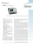
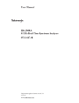
2967iss13.qxd
01/Dec/2004
10:09
Page 1
Wireless
2967 GSM 900/1800/1900 Radio Test Set
High Performance GSM 900/1800/1900 and analog test solution with digital test incorporating
Dual Band functionality. This product can be used in conjunction with PhoneTest software
•
Supports GSM 900/1800/1900 (GSM)
and Phase 2 GSM measurements
•
Available with PhoneTest software suite
•
Power and phase profile plots for normal
and access bursts to aid diagnostics
•
Full range of BER/RBER/FER measurements for receiver testing
•
Dual band functionality
•
Manual, GO/NO GO and fully programmable testing
•
Supports AMPS, TACS, NMT and MPT
1327 trunking
•
Full range of analog instrumentation
The 2967 Radio Test Set supports all the protocols required to perform measurements on
GSM 900/1800/1900 MHz systems. In addition,
it supports analog cellular standards TACS,
AMPS, NMT and the world-wide trunking systems based on MPT 1327.
Based on ETSI GSM11.10 recommendations,
the 2967 tests all the essential RF, audio and DC
parameters quickly and easily in both Service
and Production environments.
Unlike GSM only radio test sets, the 2967
includes a host of RF instrumentation and analog/digital facilities which are invaluable for performing diagnostics, radio alignment and parametric tests.
High-speed testing is ensured by use of pre-programmed test
sequences, fully user configurable for depth of test, running on a
multi-processor test platform. Further speed enhancements are
obtained by performing simultaneous TX or RX measurements over
a specified number of bursts using remote control commands.
GSM 900 Phase two testing is fully supported in the 2967.
Extensive GSM Functionality
The 2967 emulates a GSM 900/1800/1900 base station allowing
mobiles to be tested in the same way that they operate on a real system without user knowledge of manufacturer specific test modes.
Network simulation is especially useful when checking for configuration problems on mobiles. Transmitter tests measure power, peak
and RMS phase error, frequency error and timing error, all as specified in GSM11.10. Graphical displays, with fast update rates, show
power profile and phase profile against the relevant GSM masks, for
both shortened and normal bursts, to aid radio alignment. Receiver
testing covers all classes of BER, RBER and FER readings, and automatic sensitivity measurement is also provided.
New system features have been added to test additional terminal
facilities, IMSI detach, Cell Barring and Minimum RF level for
Access.
The 2967 covers the Phase 2 frequency plan (E-GSM) and supports
the lower power levels (PL16-PL19).
Dual Band Functionality
Multi-band capability has been added to the test functions of the
2967, allowing full testing of multi-band mobiles in manual test,
autorun and remote, including PhoneTest applications. Registration
and calls to and from the mobile can be tested in the GSM 900 and
1800/1900 bands with handoff carried out from band to band.
For the very latest specifications visit
www.aeroflex.com
2967iss13.qxd
01/Dec/2004
10:09
Page 2
Spectrum Analysis
The inbuilt RF spectrum analyzer allows fast, high resolution analysis of signals applied either directly to the RF ports or off-air via an
antenna. It carries many features only usually found on stand-alone
analyzers, such as full span, selectable resolution bandwidth filters
and two steerable markers.
The 2967 produces print outs at the touch of a key, providing the terminal information and test results in a concise form. ‘Brief Test’, for
example, gives a three channel summary in a single page. The
pass/fail count is given at the bottom of the page so good radios can
be verified quickly and bad ones can be identified.
The 2967 print-outs also include the instrument serial number as
well as time/date stamping, and can also be annotated with the
Company name and User name for quality control. Printouts can be
stored to a standard PCMCIA2 memory card.
Manual and Automatic Operation
The 2967 User Interface offers ready access to many sophisticated
functions. The instrument extends the original test set interface
established by the 2955 into the world of digital communications.
The large bright, high resolution screen and the 22 associated softkeys on the front panel have significant benefits in terms of user comfort, and hence efficiency in Manual test modes.
The tracking generator facility (with offset tracking) is provided for
RF module characterization. With a useable frequency range of 100
kHz to 1 GHz and 1.3 GHz to 2.2 GHz, the spectrum analyzer supports IQ modulator alignment and the testing of internal local oscillators and IF systems. IQ alignment tests are recommended on most
popular GSM terminals.
Advanced GSM Measurements
The 2967 performs advanced GSM measurements for detailed fault
diagnosis in production and advanced service centre environments.
For radios that refuse to register or go into conversation, the 2967’s
capability to analyze the access (RACH) bursts is invaluable. All
transmitter measurements are automatically triggered on these
bursts to help the user isolate problems.
An advanced Mobile Tuning Range Test Capability (Warping) is also
available. With this facility (Option 22) the BCCH (Broadcast
Control Channel) frequency and data rate can be varied in controlled
steps, enabling mobiles with poor reference oscillators to be identified in Manual and Automatic modes of operation.
For complete versatility, the 2967 can be used to transmit or receive at
any frequency within the 10 MHz to 1 GHz band, 1.709 to 1.991 GHz
Rx and 1.709 to 1.991 GHz Tx frequencies and radios can be tested
in test modes, without signaling and synchronization.
For automatic testing, the 2967 includes four built-in test programs
ranging from simple call processing to comprehensive performance
testing. These test programs are easy to configure – individual tests
can be turned on and off, limits changed and averaging periods optimized. For complete flexibility, the 2967 can be programmed through
MI-BASIC.
PhoneTest
The 2967 can be enhanced by using PhoneTest, which is a PC based
solution running on Windows 95/98 or Windows NT, for GSM
900/1800/1900 testing. PhoneTest brings a new dimension to Radio
Test Set applications by introducing more than just the ability to test
digital cellular handsets. The PhoneTest suite of programs comprises four component parts, a control driver package, PhoneTest-Repair,
PhoneTest-Manager and PhoneTest-Exchange, providing a complete
service workshop logistics solution.
Proven Analog Cellular Testing
For analog cellular testing IFR is established as the de facto industry
standard. The 2967 provides the fundamental measurements
required (e.g. broadband power, FM deviation, SINAD) and a range
of advanced diagnostic facilities, such as the unique 40 kHz FFT
analyzer and 500 kHz oscilloscope.
TACS, AMPS and NMT come as options which support most country variants.
Test Program Generation Made Easy
The internal MI-BASIC controller allows users to write programs
using the internal automatic test routines and the standard instrument functions and measurements. Conventional BASIC functions
are supported such as mathematical operations, branching and looping.
Display of Mobile Reports
The 2967 reports equipment and subscriber details during registration and call placement. The IMSI and IMEI are displayed, as are
power-class, revision (Phase 1 or Phase 2), and encryption capability
(A5/1 or A5/2), frequency and short message service capabilities.
Programs can be written using a standard PC text editor and downloaded, via RS-232, to the test set. The program then remains in the
instrument even after switch off. A program loaded into the instrument can be copied onto a memory card and then transferred quickly and easily to another unit.
2967iss13.qxd
01/Dec/2004
10:09
Page 3
APPLICATIONS
audio analyzer aid rapid fault diagnosis.
Production
Go/No Go Testing
For the production environment the 2967 can be controlled fully over
GPIB or RS-232. These interfaces come as standard. Versatility is
paramount; all of the internal test sequences can be modified easily
by the user – particular tests can be selected/deselected, parameters
and limits can be adjusted to suit.
Go/No Go testing is essential to maintain quality in production, distribution and service. In this application, test speed and ease-of-use
are key; the 2967 delivers on both counts.
For GSM 900/1800/1900, commands are available to perform and read
back the results of either all the TX tests or all the RX tests simultaneously giving a significant time saving.
For more involved testing the unit is fully programmable via the internal MI-BASIC interpreter, allowing the user to write custom test programs. Via this programming language the user has access to all of the
internal tests and more: RS-232 read/write can be used to control a
radio in test modes and read or write calibration data; four logic controls on the rear of the instrument can be used to drive mechanical
actuators. Programs downloaded into the instrument can be copied
onto the memory card then quickly and easily transferred to other
units.
SPECIFICATION
GENERAL INFORMATION
Certain characteristics are shown as typical. These provide additional
information for use in applying the instrument but they are unwarranted.
(Applies to version 7.00 and above)
RF SIGNAL GENERATOR
DIGITAL SIGNAL GENERATOR
FREQUENCY
Range
800 MHz to 1 GHz
Alignment
Most modern cellular phones, whether analog or digital, contain few
if any mechanical trimmers – most calibration, or ‘phasing’, is carried
out electrically via the keypad or a local PC.
For calibration, the 2967 shows all of the fundamental measurements
on the screen at the same time. Rapid update rates simplify alignment. Calibrating the radio for power, frequency and modulation
accuracy is straight-forward using the instrument’s bar charts and
graphical displays.
1709 MHz to 1991 MHz
Resolution
1 Hz to 1 GHz
2 Hz to 1991 MHz
Indication
10 digit display
Setting
Keyboard entry, delta increment/decrement function and rotary variable
control
Accuracy
As frequency standard
OUTPUT LEVEL
Range
One-port Dx modes:
MI-BASIC provides full access to the RS-232 port and all measurement functions, making the standard instrument suitable for closedloop alignment applications.
N-Type socket:
–135 dBm to –45 dBm
TNC socket:
–135 dBm to –25 dBm
Two-port Dx modes:
N-Type socket:
–135 dBm to –35 dBm
TNC socket:
–135 dBm to –15 dBm
Resolution
Service
In the field, many faults are simple connector, antenna or battery
problems. These can often be identified visually. To locate more complex faults, e.g. unable to register, those that result from component
or solder joint failure, sophisticated test tools are required. The 2967
TCH mode allows phones to be tested in test modes. Under Manual
mode the instrument behaves as a signal generator and, at the same
time, a ‘free-running’ receiver. No synchronization between the
uplink and downlink is required.
Standard features, not available on GSM specific test sets, such as
the spectrum analyzer, oscilloscope, multimeter and the unique FFT
For the very latest specifications visit
0.1 dB
Indication
4 digits plus sign (dBm, dB µV, µV, mV PD/EMF)
Accuracy
N-Type socket single port duplex
±1.5 dB
±1.0 dB over the temperature range 15 to 35°C
www.aeroflex.com
2967iss13.qxd
01/Dec/2004
10:09
Page 4
Sub Harmonics
1709 to 1991 MHz <-40 dBc
GMSK MODULATION – INTERNAL
Frequency Range
800 MHz to 1 GHz, useable to 1.15 GHz
1.805 to 1.88 GHz (GSM 1800)
1.930 to 1.99 GHz (GSM 1900)
Bt
0.3
Phase Error (in useful part of burst)
Dynamic Range
0 dBm to +47 dBm
Power Profile Dynamic Range
44 dB
Power Reading
Average power over useful part of burst
Burst Type
Normal/Access
Indication Units
dBm
<1° RMS
Resolution
<4° peak
0.1 dB
BER METER
Indication
3 digits and bar chart with peak hold
Types
BER Class I
BER Class II
RBER Class Ib
RBER Class II
FER
Range
0 to 99%
Resolution
0.001%
Indication
4 digits and bar chart with peak hold
Features
Adjustable Sample Size
Duration Indication
% Settled Indication
Power profile against GSM11.10 template
Normal/Access bursts
Full burst
Useful Part
Ramps
Accuracy
±0.6 dB for temperatures in the range 15 to 35°C
See also under Environmental/User Calibration
GMSK MODULATION
Frequency Range
800 MHz to 1 GHz
1709 MHz to 1991 MHz
Phase Error Range
10° RMS
±30° peak
Burst Type
Normal/Access
Resolution
0.1°
Indication
3 digits and bar chart with peak hold
Phase profile
Accuracy
Better than 0.3° RMS at 5°
Better than 4° peak
RF POWER METER (BURST)
Frequency Range
800 MHz to 1 GHz
1.709 GHz to 1.991 GHz
BURST TIMING METER
Burst Type
Normal/Access
Range
–128 to +127 bits
2967iss13.qxd
01/Dec/2004
10:09
Page 5
Resolution
Resolution
0.01 bits
0.1 dB
Indication
Indication
4 digits plus sign (dBm, dB µV, µV, mV PD/EMF)
5 digits
Accuracy
Accuracy
N-Type socket:
±0.1 bits
±1.2 dB up to 575 MHz for levels above -120 dBm
GENERAL FEATURES (SYSTEMS)
±1.75 dB up to 1 GHz for levels above –120 dBm
Test Modes
±1.3 dB up to 1 GHz over the temperature range 15 to 35°C
Manual Test/Auto Test
Carrier On/Off
Auto Test Programs
Keyboard operation, reduces signal generator output to less than
–120 dBm
Call Processing Only
Call and RF Testing
Brief Testing
Comprehensive Testing
User Defined Test
Digital Parametric Auto Test Routines
Tx Timing
Tx Power Level
Tx Power Profile
Tx Frequency Error
Tx RMS Phase Error
Tx Peak Phase Error
Rx BER Class I
Rx BER Class II
Rx RBER Class Ib
Rx RBER Class II
Rx Frame Erasure
Rx Sensitivity
Rx RSSI Report
Dual band handoff
Reverse Power Protection
N-Type socket: With instrument switched on 150 W. Overload indicated
by visual and audible warning.
TNC socket: Protection up to 10 W. Reset available on removal of RF
power. Excess power indicated by visual and audible warnings.
Output Impedance
50 Ω nominal
VSWR
N-Type socket:
better than 1.2 up to 500 MHz;
better than 1.3 up to 1 GHz (typically 1.2),
better than 1.4 up to 1991 MHz (typically 1.3)
TNC socket: typically 1.3 at 900 MHz, typically <1.5 at 1991 MHz
SPECTRAL PURITY
ANALOG SIGNAL GENERATOR
Residual FM (CCITT weighted)
FREQUENCY
15 to 35°C
Range
Less than 6 Hz RMS up to 575 MHz
Less than 12 Hz RMS up to 1 GHz
Less than 24 Hz RMS up to 1991 MHz
100 kHz to 1 GHz, useable 90 kHz to 1.15 GHz
Resolution
Residual AM (CCITT weighted)
1 Hz
Less than 0.05% RMS
Indication
Harmonics
10 digit display
Better than –30 dBc for levels up to +4 dBm (TNC)
Setting
Keyboard entry, delta increment/decrement function and rotary variable
control
Accuracy
Better than –30 dBc for levels up to –16 dBm (N-Type)
Spurious Signals
Better than –45 dBc for carrier frequencies from 100 kHz to 36 MHz;
As frequency standard
OUTPUT LEVEL
Range
Better than –50 dBc for carrier frequencies 36 MHz to 1 GHz.
SSB Phase Noise (20 kHz offset)
Better than –114 dBc/Hz up to 575 MHz
One-port Dx modes:
N-Type socket: –135 dBm to –40 dBm
TNC socket: –115 dBm to –20 dBm
Rx Test and two-port Dx modes:
N-Type socket: –135 dBm to –10 dBm (–20 dBm with AM)
TNC socket: –115 dBm to + 10 dBm (0 dBm with AM)
For the very latest specifications visit
Better than –108 dBc/Hz up to 1 GHz.
Better than –102 dBc/Hz up to 1991 MHz
RF Carrier Leakage
Less than 0.5 µV PD generated at the carrier frequency, up to 1 GHz,
across a 50 Ω load by a 2-turn 25 mm loop, 25 mm from the surface
of the instrument with the output level at <-60 dBm and terminated in
a 50 Ω sealed load.
www.aeroflex.com
2967iss13.qxd
01/Dec/2004
10:09
Page 6
Less than 1.0 µV PD generated at the carrier frequency, from 1 GHz to
2 GHz, across a 50 Ω load by a 2-turn 25 mm loop, 25 mm from the
surface of the instrument with the output level at <-60 dBm and terminated in a 50 Ω sealed load.
AMPLITUDE MODULATION – INTERNAL
Frequency Range
100 kHz to 400 MHz, useable to 1.15 GHz
AM Depth Range
0 to 99%
Resolution
0.1%
Indication
3 digits
Setting
Keyboard entry, delta increment/decrement function and rotary variable
control
Accuracy(1) (up to 85% AM)
±4% of setting ±1 digit for modulation frequency 1 kHz.
±6% of setting ±1 digit for modulation frequencies from 30 Hz to
10 kHz.
±8% of setting ±1 digit for modulation frequencies from 10 kHz to
20 kHz.
Distortion
Less than 1% at 1 kHz for modulation depths up to 30%, CCITT
weighted.
Less than 2% for modulation frequencies from 100 Hz to 20 kHz and
depths up to 85%.
Modulation Frequency
Accuracy
(1)
±3% ±1 digit at 1 kHz over the range 15 to 35°C (0.1% per °C outside this range)
Typically ±3% ±1 digit for modulation frequencies from 20 Hz to
5 kHz.
Typically ±7% ±1 digit for modulation frequencies from 5 kHz to
20 kHz.
Typically ±10% ±1 digit for modulation frequencies from 20 kHz to
75 kHz.
Distortion(1)
Less than 0.5% for modulation frequencies from 250 Hz to 5 kHz (for
deviation 1 kHz to 800 kHz).
Less than 1% for modulation frequencies from 50 Hz to 20 kHz (for
deviation 1 kHz to 800 kHz).
Modulation Frequency Range(6)
20 Hz to 20 kHz Mod generators 1, 2, 3 or
20 Hz to 100 kHz Mod generator 4
Resolution
0.1 Hz
FREQUENCY MODULATION – EXTERNAL
Input Impedance
Nominally 1 MΩ in parallel with 100 pF
Frequency Range
As internal FM
Modulation Frequency Range
DC to 100 kHz (DC coupled)
10 Hz to 100 kHz (AC coupled)
Range: 20 Hz to 15 kHz for carrier frequencies up to 36 MHz; 20 Hz
to 20 kHz for carrier frequencies up to 400 MHz.
Input Sensitivity
Resolution: 0.1 Hz below 10 kHz; 1 Hz below 20 kHz.
Accuracy
AMPLITUDE MODULATION – EXTERNAL
Input Impedance
Nominally 1 MΩ in parallel with 100 pF
Frequency Range
As internal AM
Modulation Frequency Range
As internal AM with AC or DC coupling
Accuracy
As internal ±2%
Input Sensitivity
1 VRMS for indicated modulation depth
FREQUENCY MODULATION – INTERNAL
Frequency Range
100 kHz to 1 GHz, useable 90 kHz to 1.15 GHz
Indication
4 digits
Setting
Keyboard entry, delta increment/decrement function and rotary variable
control
2.828 V pk-pk for indicated deviation
As internal ±2% for frequencies up to 20 kHz
PHASE MODULATION – INTERNAL
Frequency Range
100 kHz to 1 GHz, useable to 1.15 GHz
Indication
4 digits
Setting
Keyboard entry, delta increment/decrement function and rotary variable
control
Accuracy
±5% ±1 digit for modulation frequencies from 250 Hz to 3.4 kHz,
over the range 15 to 35°C (0.1% per °C outside this range)
Distortion(1)
Less than 1% for modulation frequencies from 250 Hz to 5 kHz (for
deviation 1 rad to 160 rads).
Modulation Frequency
Range: 250 Hz to 5 kHz
Resolution
0.1 Hz
2967iss13.qxd
01/Dec/2004
10:09
Page 7
PHASE MODULATION – EXTERNAL
1 Hz from 5 kHz to 50 kHz
Input Impedance
10 Hz from 50 kHz to 500 kHz
Nominally 1 MΩ in parallel with 100 pF
Indication
6 digits
Frequency Range
As internal phase modulation
Accuracy
As frequency standard ±1 digit ± resolution
Modulation Frequency Range
250 Hz to 5 kHz
Sensitivity
On barchart greater than 25% FSD (DC coupled)
Input Sensitivity
2.828 V pk-pk for indicated deviation
AUDIO SINAD METER
Accuracy
Frequency
As internal ±2%
1 kHz default. User selectable up to 20 kHz
INTERNAL MODULATION AND AUDIO SOURCES
Up to 6 tone sources can be assigned as 3 modulation generators and
3 audio tone generators.
Modulation Modes
SINAD Range
5 to 50 dB
Resolution
Internal generators may be assigned to AM, FM, ΦM.
0.1 dB for readings less than 20 dB
0.2 dB for readings less than 25 dB
AUDIO VOLTMETER
Indication
3 digits and barchart with peak hold
Input Impedance
Nominally 1 MΩ in parallel with 100 pF
Accuracy (Bandpass filter selected)
±0.5 dB ± resolution
Frequency Range
DC and 20 Hz to 500 kHz
Sensitivity
100 mV for 46 dB SINAD
AC only 20 Hz to 500 kHz
Polarized DC less than 10 Hz
AUDIO DISTORTION METER
Level Ranges and Resolution
0-10, 0-30, 0-100 mV,
0-300 mV,
0-1 V
0-3 V
0-10 V
0-30 V
resolution
resolution
resolution
resolution
resolution
resolution
Frequency
0.1 mV
0.3 mV
1 mV
3 mV
10 mV
30 mV
1 kHz default. User selectable up to 20 kHz
Distortion Range
0 to 30%
Resolution
All RMS reading, autoranging or fixed
0.1% distortion for readings greater than 1%
0.2% distortion for readings less than 1%
Level Indication
4 digits and barchart with peak hold
Indication
Level Accuracy (DC Coupled)(3) (5)
3 digits and bar chart with peak hold
+2% of reading +1 mV + resolution, DC and 100 Hz to 20 kHz.
+4% of reading +1 mV + resolution, 40 Hz to 100 kHz.
Level Accuracy (AC Coupled)
(3)
±2% of reading ±1 mV, ± resolution 150 Hz to 20 kHz.
±4% of reading ±1 mV, ± resolution 100 Hz to 100 kHz.
Residual Noise
100 µV RMS CCITT weighted
Accuracy
±5% of reading ± resolution (bandpass filter selected)
Sensitivity
100 mV for 0.5% distortion
AUDIO S/N METER
S/N Range
0 to 100 dB
AUDIO FREQUENCY METER
Range
10 Hz to 500 kHz
Resolution
0.1 dB for readings less than 50 dB
0.2 dB for readings less than 70 dB
Indication
Resolution
0.1 Hz from 10 Hz to 5 kHz
For the very latest specifications visit
3 digits and bar chart with peak hold
www.aeroflex.com
2967iss13.qxd
01/Dec/2004
10:09
Page 8
Accuracy
±0.5 dB ± resolution
Sensitivity
2 V for 60 dB, 200 mV for 40 dB
Marker Indication
Level: M1, M2, δM
Frequency: M1, M2, ∆M
AUDIO BAR CHARTS
AUDIO OSCILLOSCOPE
Displays: AF voltage, SINAD, Distortion, S/N.
Operating Modes
Vertical Resolution: 1% of full scale.
Single or Repetitive sweep
Frequency Range
DC to 500 kHz
10 Hz to 500 kHz (AC coupled)
Glitch Catching
1 µs minimum
Voltage Ranges
2 mV/div to 20 V/div in a 1, 2, 5 sequence
Voltage Accuracy
±5% of full scale
Timebase
5 µs/div to 10 s/div in a 1, 2, 5 sequence
Timebase Accuracy
As frequency standard
Trigger Mode
Auto trigger
Marker Indication
Level: M1, M2, δM
Time: M1, M2, ∆M
Graticule
10 Horizontal by 8 Vertical divisions, can be magnified to full screen
AUDIO FFT ANALYZER
Span Widths
50 Hz to 50 kHz in a 5, 10, 25 sequence
Above 40 kHz signals are attenuated by 80 dB/octave
Graticule
10 Horizontal by 8 Vertical divisions, can be magnified to full screen
Level Reference (top of screen)
10 mV to 20 V, in a 1, 2, 5 sequence
Level Accuracy
±0.3 dB 100 Hz to 15 kHz; typically ±1 dB 40 Hz to 40 kHz
Vertical Scaling
1, 2, 5, 10 dB/div
Dynamic Range
60 dB
Max hold facility
Audio Sweep facility
DC to 20 kHz
Ranging: Autoranging, range hold or manual selection (up/down), 1, 3,
10 sequence with hysteresis.
With peak hold facility.
AUDIO AND MODULATION FILTERS
300 Hz Lowpass (±0.1 dB less than 150 Hz, ±0.2 dB, 150-200 Hz
relative to 100 Hz).
300 Hz to 3.4 kHz Bandpass (±0.4 dB, 400 to 2100 Hz relative to
1 kHz).
5 kHz Lowpass (±0.3 dB at <3 kHz relative to 1 kHz).
20 kHz Lowpass ±0.3 dB at <12 kHz, typically –0.9 dB at <15 kHz
and –3 dB at 20 kHz relative to 1 kHz.
CCITT Psophometric
C-MESSAGE
See also under Environmental/User Calibration
MULTIMETER
Input Terminals
3 x 4 mm, ‘Volt/Ohm’, ‘Current’ and ‘Common’
Maximum Input Voltage
300 V (CAT II) with respect to instrument chassis
Accuracy specifications apply with a maximum common mode voltage of 25 V
VOLTMETER
Voltage Range
0 to 300 V, 0 to 30 V, 0 to 3 V, 0 to 300 mV, Terminals, ‘Volt/Ohm’
and ‘Common’, maximum crest factor 3:1 at range full scale
Frequency Range
Polarized DC or 40 Hz to 1 kHz
Input Impedance
Nominally 6 MΩ in parallel with 100 pF
Resolution
0.1% of FSD
Accuracy (5)
DC: ±3% of reading ±2 mV ±1 digit
AC + DC: ±3% of reading ±3 mV ± 1 digit
See also under Environmental/User Calibration
Indication
3 digits and bar chart with peak hold
AMMETER
Current Range
0 to 1 A and 0 to 10 A
2967iss13.qxd
01/Dec/2004
10:09
Page 9
Frequency Range
Polarized DC or 40 Hz to 1 kHz
Dynamic Range (Auto tuned)
As RF Power Meter (broadband)
Frequency Range (Auto tuned)
Resolution
1 mA below 1 A; 10 mA below 10 A
10 MHz to 999.9 MHz
Sensitivity
Accuracy
DC: ±5% of reading ±50 mA ±1 digit
AC + DC: ±5% of reading ±150 mA ±1 digit
Manual tuned: –100 dBm (TNC) dependent on receiver bandwidth in off
air test mode
Offset Frequency Range
Indication
3 digits and bar chart with peak hold
RESISTANCE METER
Resistance Ranges
100 Ω, 1 kΩ, 10 kΩ, 100 kΩ, 1 MΩ
Resolution
±1 MHz dependent on receiver bandwidth
RF POWER METER (BROADBAND)
Frequency Range
100 kHz to 1 GHz
Dynamic Range (Auto tuned)
1 Ω below 1 kΩ or 3 digits
Accuracy(5)
10 mW to 150 W (N-Type), 100 µW to 0.5 W (TNC)
Power Reading
±5% of reading ±1 Ω ±1 digit
Continuity Test
Continuous tone if reading is less than 10 Ω
Indication
True mean power
Indication Units
Watts
Resolution
4 digits and bar chart with peak hold
RF FREQUENCY ERROR METER
Frequency Range
800 MHz to 1 GHz
1.709 GHz to 1.991 GHz
Frequency Error Range
±5 kHz
Better than 1%
Indication
3 digits and barchart with peak hold
Accuracy(5)
100 kHz to 500 MHz:
±7.5% (0.3 dB), 0.1 W to 50 W (N-Type)
±10% (0.4 dB), 20 mW to 150 W (N-Type)
±12% (0.5 dB), 200 µW to 50 mW (TNC)
500 MHz to 1 GHz:
Burst Type
Normal/Access
Resolution
±12% (0.5 dB), 20 mW to 150 W (N-Type)
±15% (0.6 dB), 200 µW to 50 mW (TNC)
100 kHz to 1 GHz:
0.1 Hz.
±7.5% (0.3 dB), 0.1 W to 50 W (N-Type)
±10% (0.4 dB) 1 mW to 50 mW (TNC)
Indication
3 digits and bar chart with peak hold
Accuracy
For ambient temperatures in the range 15 to 35°C.
See also under Environmental/User Calibration
±30 Hz
Maximum Safe Continuous Rating
RF FREQUENCY METER
N-Type: 50 W
TNC: 0.5 W; overload protected to 10 W
Range
100 kHz to 1 GHz
Resolution
1 Hz or 10 Hz selectable
Indication
Up to 10 digits
Intermittent Rating
N-Type: 150 W for limited periods, typically 2 minutes at 20°C. Typical
off to on ratio is 6:1. Overload indicated by audible and visual warning
RF POWER METER (SELECTIVE)
Frequency Range
100 kHz to 1 GHz
Accuracy
As Frequency Standard ±2 Hz ± resolution
IF Bandwidth
300 Hz to 30 kHz in a 1, 3, 10 sequence and 110 kHz, 280 kHz and
3 MHz
For the very latest specifications visit
www.aeroflex.com
2967iss13.qxd
01/Dec/2004
10:09
Page 10
Dynamic Range (Manually tune)
0 dBm to +50 dBm (110 kHz IF bandwidth) (N-Type)
–90 dBm to +20 dBm (110 kHz IF bandwidth) (TNC)
Power Reading
Average
Indication Units
dBm
Resolution
0.1 dB
Indication
3 digits + barchart with peak hold
Accuracy(5)
Typically ±2.5 dB N-Type and TNC
See also under Environmental/User Calibration
RF SPECTRUM ANALYZER
Frequency
Expanded Mode
Can be made to occupy full screen for high definition
Markers
M1 and M2
Indication
Level: M1, M2, δM
Frequency: M1, M2, ∆M
TRACKING GENERATOR
Available in RF TEST mode
Frequency Range
100 kHz to 1 GHz
Level Range
–135 dBm to +10 dBm
Offset Tracking
Allows testing of mixers, IFs, fundamental and 2nd harmonic analysis
(up, down, x2, ÷2)
MODULATION ANALYZER
Range: 100 kHz to 1 GHz, useable from 30 kHz to 1.05 GHz
1.71 GHz to 1.991 GHz, useable from 1.3 GHz to 2.2 GHz
Spans
500 Hz/div to 100 MHz/div, in a 1, 2, 5 sequence up to 1 GHz
1 MHz/div max, 1.7 GHz to 1.99 GHz
50 kHz/div max 1.3 GHz to 2.2 GHz
Resolution Bandwidth
300 Hz to 300 kHz in a 1, 3, 10 sequence and 3 MHz (automatically
selected according to span and manually selectable).
Video bandwidth, auto selection 100 Hz, 1 kHz and 3 kHz.
Filter Shape
Nominally 3 dB/60 dB, 1:11 (300 Hz to 30 kHz bandwidth)
Reference Level (top of screen)
–100 dBm to +70 dBm
On Screen Dynamic Range
80 dB
Vertical Resolution
0.5 dB on 10 dB/div, 0.05 dB on 1 dB/div
Level Accuracy(5)
Typically ±2.5 dB
See also under Environmental/User Calibration
Sweep Speeds
Optimum sweep speed selected according to span and resolution
bandwidth
Modes
Single sweep and continuous
Graticule
10 horizontal by 8 vertical divisions
Dynamic Range (Auto tuned)
As RF Power Meter (Broadband)
Sensitivity (Manual tuned)
N-Type –30 dBm (110 kHz IF bandwidth).
TNC –50 dBm (110 kHz IF bandwidth).
TNC (off-air test mode) –101 dBm (2 µV 10 dB SINAD in 30 kHz IF
bandwidth and CCITT weighting).
Demodulation
Accuracy maintained on signals greater than –60 dBm
Receiver Bandwidths
300 Hz to 30 kHz in a 1, 3, 10 sequence and 110 kHz, 280 kHz and
3 MHz.
Demodulation Filters
As audio analyzer plus 5 kHz lowpass (±0.3 dB at less than 3.4 kHz
relative to 1 kHz)
Audio Output
Available in to an internal loudspeaker, demodulated output or accessory socket for external loudspeaker or headphones.
Demodulated Output
Nominal output impedance less than 10 Ω. Output voltage is range
dependent (2 V peak at top of range)
Switching Speed
Nominally less than 1 ms channel to channel up to 50 MHz apart,
settling to within 1 kHz of final frequency
Squelch
A manual squelch control is provided with a variable threshold.
AMPLITUDE MODULATION
Frequency Range
100 kHz to 1 GHz
2967iss13.qxd
01/Dec/2004
10:09
Page 11
Indication
Modulation Frequency Range
3 digits and bar chart with peak hold.
20 Hz to 20 kHz
Accuracy(1) (3) (5)
AM Depth Range
0 to 99.9%
±5% ± resolution, 2 to 20 rads
Resolution
Demodulation Distortion(1)
0.1% AM
Less than 0.5% at 1 kHz, CCITT weighted.
Indication
AUDIO GENERATORS
3 digits and bar chart with peak hold.
See section on modulation generators for interaction of audio and
modulation generators
Accuracy (up to 85% AM)(1)(5)
±3% of reading, ±1% AM, 250 Hz to 5 kHz.
FREQUENCY
Typically ±5% of reading, ±1% AM, 50 Hz to 15 kHz.
Range(6)
Demodulation Distortion(1)
1 Hz to 20 kHz AF Gens 1, 2 and 3 or
Less than 1% at 1 kHz, CCITT weighted
1 Hz to 100 kHz AF Gen 4
Residual AM
Setting
Less than 0.1% AM, CCITT weighted
Keyboard entry, delta increment/decrement function and rotary control.
FREQUENCY MODULATION
Indication
Frequency Range
6 digits
1 MHz to 1 GHz
Resolution
Modulation Frequency Range
0.1 Hz
20 Hz to 20 kHz
Accuracy
20 Hz to 100 kHz when Option 08 fitted
As frequency standard
Deviation Range
LEVEL
0 to 100 kHz
Range
Resolution
0.1 mV to 5 V RMS (maximum AF output 7 V peak, all generators
combined)
10 Hz below 10 kHz deviation; 100 Hz below 100 kHz deviation
Setting
Indication
Keyboard entry, delta increment/decrement function and rotary control
3 digits and bar chart with peak hold.
Indication
Accuracy(1) (3) (5)
4 digits
±3% ± resolution for modulation frequency of 1 kHz.
±5% ± resolution for modulation frequencies from 100 Hz to 15 kHz.
±10% ± resolution for modulation frequency 15 kHz to 100 kHz opt
08 only.
Demodulation Distortion(1)
Less than 0.5% at 1 kHz, CCITT weighted.
Residual FM
Less than 25 Hz RMS CCITT weighted.
PHASE MODULATION
Frequency Range
1 MHz to 1 GHz
Modulation Frequency Range
250 Hz to 5 kHz
Deviation Range
0 to 20 rads
Resolution
Resolution
0.1 mV
Accuracy
±3% ±1 digit, 250 Hz to 5 kHz
±5% ±1 digit, 10 Hz to 20 kHz
±10% ±1 digit, 20 kHz to 75 kHz
Output Impedance
Nominally 5 Ω
Protection
Maximum applied voltage 50 V
SIGNAL PURITY
Distortion(2)
Less than 0.5% at 1 kHz measured in a 30 kHz bandwidth
Less than 1% from 20 Hz to 20 kHz measured in an 80 kHz bandwidth
Typically 0.1% for levels greater than 100 mV
0.01 rads
For the very latest specifications visit
www.aeroflex.com
2967iss13.qxd
01/Dec/2004
10:09
Page 12
Sideband Selection
Residual Noise
Less than 50 µV RMS (CCITT weighted)
– LSB, USB, CW
SSB Rx
DC Offset
Less than 10 mV
SIGNALING ENCODER/DECODER
Sequential tones functions
Sideband Generator
– as RF Gen (AM mode)
Offset measurement
– to 0.1 Hz resolution
SINAD
– as SINAD meter
Distortion
– as Distortion meter
Note: No audio is available in SSB option.
Encodes and decodes up to 40 tones.
CCIR, ZVEI, DZVEI, EEA, EIA or user defined.
GENERAL FEATURES
Any of the tones may be extended.
INTERFACES
Continuous, burst and single step modes available.
Keyboard and Display
Logical color coded keyboard with bright high resolution CRT
User defined tones
Up to three frequency plans may be defined and stored within the
2967 for sequential tones.
Any of the standard tone frequency plans may be copied to user
defined and modified.
Tone length 10 ms to 1 s.
GPIB
Full control of all major instrument functions via the GPIB interface.
Flexibility is further enhanced by IFR Ltd’s implementation of IEEE488.2.
Capability
Extended tone length 100 ms to 10 s.
Complies with the following subsets as defined in IEEE-488.1-1978:SH1, AH1, T6, TE0, L4, LE0, SR1, RL1, PP0, DC1, DT1, C1, E1.
CTCSS tones mode
Standard tone frequencies may be selected from a menu
Serial
DTMF Encoder/Decode
Generation and decode of DTMF tones, displaying Hi/Lo frequencies,
frequency error, timing information and twist
Serial interface is provided for connection of RS-232 for instrument
remote control. 9 Way socket.
Parallel
DCS Encode/Decode
Generation and decoding of digitally coded squelch
POCSAG generator
Connector 25 way female D-Type. Provision made for graphics screen
dump. A selection of printer drivers are included.
Accessory Socket
Generation of POCSAG code CCIR No.1
Rec 584. Bit rates from 400 to 9600 bit/s
Allows the connection of various optional accessories.
With suitable adapters is compatible with most 2955 series accessories.
AUDIO MONITOR
Audio and demodulation signals may be monitored via the internal
loudspeaker or via the accessory socket output or BNC socket on the
rear panel.
Memory Card
Meets PCMCIA2/JEIDA – 4 standard. The memory card facility allows
the storage of results, set ups and MI-BASIC programs.
Video Output
SSB OPTION
Color, compatible with most VGA monitors.
SSB Tx
15 way Sub Miniature D Type.
Frequency, range and
meter accuracy
– as RF frequency
Power, level and
accuracy
– as Broadband power meter
Detection Range
– 100 µV to 150 W
AF Demod range
– 10 Hz to 5 kHz
Demod distortion
– <2% @ 1 kHz CCITT
weighted
FREQUENCY STANDARD
Carrier and Alternate
s/band suppression
– Better than –50 dBc
Sideband/CW Analyzer
– max 5 kHz full span
frequency range
Spectrum Analyzer
– as RF spectrum analyzer
Audio Generator
– two – as audio generator
Internal Frequency Standard Output
Frequencies
10 MHz and 13 MHz
Level
Nominally 2 V pk-pk
Output Impedance
Nominally 50 Ω
Temperature Stability
Better than 5 in 108, 5 to 50°C.
2967iss13.qxd
01/Dec/2004
10:09
Page 13
Audio Analyzer & Modulation Filters
Ageing Rate
Better than 1 in 107 per year, after 1 month continuous use
Warm Up Time
Less than 10 minutes to within 2 in 10 at 20°C
Multimeter:
7
External Frequency Standard Input
Frequencies
Audio Voltage
0.4%
Demod depth & deviation
0.4%
Voltage
0.5%
Current
0.5%
Storage and Transport
1, 2, 5, 10 and 13 MHz
Temperature
–40 to +70°C
Level
Greater than 2 V pk-pk, less than 5 Vpk-pk
Altitude
Up to 2500 m (pressurised freight at 27 kPa differential)
Input Impedance
Nominally 100 Ω
INTERNAL TEST SOFTWARE
POWER REQUIREMENTS
OPTION 10 NMT CELLULAR SOFTWARE
NMT450
Benelux
Austria
Malaysia
Saudi 1
Thailand
Tunisia
Poland
Czech
Slovenia
AC supply
Voltage
100 - 240 V~ (Limit 88 - 264 V~)
Supply frequency
50 - 60 Hz (Limit 45 - 66 Hz)
Power
Nominally 135 W, 260 W maximum, for future options
NMT900
NMTF
Spain
Indonesia
Saudi 2
Oman
Hungary
Russia
Bulgaria
Turkey
USER DEFINED NMT
CALIBRATION INTERVAL
OPTION 11 AMPS CELLULAR SOFTWARE
2 years
E-AMPS
ELECTROMAGNETIC COMPATIBILITY
Conforms with the protection requirements of the EEC Council Directive
89/336/EEC. Conforms with the limits specified in the following standards:
IEC/EN61326-1 : 1997, RF Emission Class B, Immunity Table 1,
Performance Criteria B
SAFETY
Conforms with the requirements of EEC Council Directive 73/23/EEC
(as amended) and the product safety standard IEC / EN 61010-1 :
2001 + C1 : 2002 + C2 : 2003 for Class 1 portable equipment, for
use in a Pollution Degree 2 environment. The instrument is designed to
be operated from an Installation Category 2 supply.
ENVIRONMENTAL
Rated Range Of Use
USER DEFINED AMPS
OPTION 12 TACS CELLULAR SOFTWARE
E-TACS
C-TACS I
J-TACS
USER DEFINED TACS
TACS-2
C-TACS II
N-TACS
OPTION 13 MPT 1327 TRUNKING SOFTWARE
Band III
UK Water
Autonet
Madeira
NZ MPT1327
USER DEFINED MPT
JRC
Hong Kong
AMT
NL-TRAXYS
PH-INDO
OPTION 14 PMRTEST SOFTWARE
0 to 50°C and up to 95% relative humidity at 40°C.
USER DEFINED PMR for FM radios
User Calibration
Analog Parametric Auto Test Routines
User calibrations are provided to maintain high accuracy for any ambient temperature (e.g. in ATE racks or in field measurements). Having
allowed the instrument to stabilize, running the user calibrations optimizes the performance at that temperature.
A change in temperature of 5°C from the calibration temperature
affects readings as below. These figures are provided as a guide to typical performance. Typical variations are as follows for a 5°C change in
temperature.
Power Meter:
N-AMPS
Burst
0.5 dB
Broadband
2%
Selective
0.5 dB
Spectrum Analyzer Level
AF Frequency
FM Deviation
Rx Distortion
Rx Sensitivity
Rx S/N
Tx Distortion
Tx Level
Tx Limiting
Tx Noise
Tx S/N
SAT Frequency
ST Frequency
Data Deviation
AF Level
Mod Frequency
Rx Expansion
Rx SINAD
Tx Compression
Tx Frequency
Tx Power Level
Tx Mod Level
Tx SINAD
SAT Deviation
ST Duration
ST Deviation
DSAT Deviation
0.5 dB
For the very latest specifications visit
www.aeroflex.com
2967iss13.qxd
01/Dec/2004
10:09
Page 14
Signalling Auto Test Routines
Registration / Roaming Update
Place Call
Clear From Mobile
Page Mobile
Handoff
Clear From Land
Speech Quality
Hook Flash
DTMF Decode
Data Performance
PTT On
PTT Off
Auto Test Pause Modes
Pause Manual Only
Pause On Failure
Pause Always
DIMENSIONS AND WEIGHT
Excluding handle, feet and covers.
Height
Width
177 mm
370 mm
(6.9 in)
(14.5 in)
Including handle, feet and covers.
Depth
540 mm
(21.2 in)
Height
203 mm
(7.9 in)
Depth
600 mm
(23.6 in)
Width
420 mm
(16.5 in)
Weight
Less than 20.5 kg (45.1 lb)
NOTES
(1)
At low modulation levels the residual AM/FM may become significant.
(2)
At low audio levels the residual noise may become significant.
(3)
Audio and Modulation filter passband errors not included.
(4)
Typical performance figures are non-warranted.
(5)
Refer to USER CALIBRATION section.
(6)
Either 3 modulation plus 3 audio generators up to 20 kHz or 1 modulation or 1
audio generator to 100 kHz.
2967iss13.qxd
01/Dec/2004
10:09
Page 15
VERSIONS AND ACCESSORIES
When ordering please quote the full ordering number information.
Ordering Numbers
Accessories
Versions
54421/001
BNC Telescopic antenna
54431/023
20 dB AF attenuator (BNC)
54112/158
Hard Transit Case
54112/157
Soft Carrying Case
54127/310
Rack Mounting Kit
59000/189
Memory Card (128 K)
54411/052
600 Ω interface and 20dB AF attenuator (requires
46884/645 Accessory socket adapter)
46884/645
Accessory socket adapter (for use with 2955 accessories)
46884/646
Accessory Socket ‘Y’ adapter
46884/560
Parallel Printer Interface Cable
46884/649
Serial port to PC Cable (25 way)
46884/650
Serial port to PC Cable (9 way)
43129/189
GPIB Cable
43130/596
Coaxial cable N-Type(m) to TNC(m) (double
screened)
AC Supply lead
54311/095
Coaxial cable N-Type(m) to N-Type(m) (1 metre)
Operating Manual
54212/001
GSM Phase 2 Plug-In TEST SIM
Multimeter Lead Kit (Two 4 mm leads to test points)
54212/002
GSM Phase 2 Full Size TEST SIM
PhoneTest Options
54311/071
TNC(m) to BNC(f) adapter
81506
PhoneTest for 2967
54311/092
N-Type(m) to BNC(f) adapter
81510
PhoneTest Bundle includes
81506/81507/81508/81509
52388/900
1 GHz Active Probe
54441/012
Power supply for probe 52388/900
81507
PhoneTest-Repair
46880/080
Service Manual
81508
PhoneTest-Manager
81509
PhoneTest-Exchange
The 2967 is now supplied with a 2 year warranty as standard
81504
PhoneTest and enabled options, site licence software
upgrade
W3
81505
PhoneLib
2967
Radio Test Set
Options
Option 01
French Language Version
Option 02
Spanish Language Version
Option 03
German Language Version
Option 09
SSB receiver option
Option 10
NMT Cellular Radio option
Option 11
AMPS Cellular Radio option (including N-AMPS)
Option 12
TACS Cellular Radio option (including N-TACS)
Option 13
MPT 1327/MPT 1343 Trunked Radio option
Option 14
PMRTEST for FM radios.
Option 16
GSM 1800
Option 17
GSM 1900
Option 22
Mobile Tuning Range Test
Contact your local Sales Outlet for details of availability of options
Supplied with
For the very latest specifications visit
Service Support
Third year warranty
Contact your local Sales Outlet for availability of these and other service plans
www.aeroflex.com
2967iss13.qxd
01/Dec/2004
10:09
Page 16
CHINA Beijing
Tel: [+86] (10) 6467 2761 2716
Fax: [+86] (10) 6467 2821
GERMANY
Tel: [+49] 8131 2926-0
Fax: [+49] 8131 2926-130
SCANDINAVIA
Tel: [+45] 9614 0045
Fax: [+45] 9614 0047
CHINA Shanghai
Tel: [+86] (21) 6282 8001
Fax: [+86] (21) 62828 8002
HONG KONG
Tel: [+852] 2832 7988
Fax: [+852] 2834 5364
SPAIN
Tel: [+34] (91) 640 11 34
Fax: [+34] (91) 640 06 40
FINLAND
Tel: [+358] (9) 2709 5541
Fax: [+358] (9) 804 2441
INDIA
Tel: [+91] 80 5115 4501
Fax: [+91] 80 5115 4502
UK Burnham
Tel: [+44] (0) 1682 604455
Fax: [+44] (0) 1682 662017
FRANCE
Tel: [+33] 1 60 79 96 00
Fax: [+33] 1 60 77 69 22
KOREA
Tel: [+82] (2) 3424 2719
Fax: [+82] (2) 3424 8620
As we are always seeking to improve our products,
the information in this document gives only a general
indication of the product capacity, performance and
suitability, none of which shall form part of any contract. We reserve the right to make design changes
without notice. All trademarks are acknowledged.
Parent company Aeroflex, Inc. ©Aeroflex 2004.
UK Stevenage
Tel: [+44] (0) 1438 742200
Fax: [+44] (0) 1438 727601
Freephone: 0800 282388
USA
Tel: [+1] (316) 522 4981
Fax: [+1] (316) 522 1360
Toll Free: 800 835 2352
w w w.aeroflex.com
[email protected]
Our passion for performance is defined by three
attributes represented by these three icons:
solution-minded, performance-driven and customer-focused.
Part No. 46891/021, Issue 13, 03/04