1
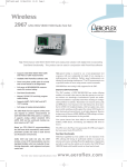
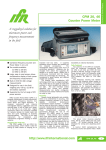
Wireless
2968 TETRA Radio Test Set
The 2968 TETRA Radio Test Set for comprehensive terminal and base station testing
•
TETRA terminal and base station test
options
•
Trunked Mode and optional Direct Mode
control a TETRA radio and then make measurements of key transmitter and receiver RF and audio parameters. Measurements are
performed accurately with speed and ease.
•
Simplex and Duplex operation
TETRA Measurements
•
Group, Individual, Phone and Emergency
call types
•
Direct or Hook signalling
•
TIPv3 compliant
•
ETSI EN 300 394-1 transmitter and
receiver measurements
•
TETRA Test (TT) registration and TT loopback BER testing
•
TI test signal generation and T1 loopback
and BER testing
•
Auto-test mode for fast terminal testing
•
Audio loopback testing for voice or tones
•
Multi-standard platform
•
Optional TETRALOG protocol analysis
•
Full span spectrum analyzer and tracking
generator
•
Audio FFT analysis
The IFR 2968 TETRA Radio Test Set is a single
box solution for testing TETRA radio terminals
and / or base stations and has been designed to
offer maximum flexibility to satisfy applications in
design, manufacturing and radio maintenance.
The test set provides all the necessary signalling to
Transmitter measurements performed on terminals and base stations include burst power, power profile, frame alignment (burst
timing error), frequency error, modulation accuracy (EVM) and
residual carrier. All are performed in accordance with ETSI EN 300
394-1. These parameters are measured for each of the different
TETRA burst types and displayed numerically on a summary screen
as well as a graphical bar chart. Individual parameters are supported by dedicated graphical displays to aid design engineering or fault
diagnosis. Demodulated symbol data for captured bursts can be displayed or output for offline storage or analysis.
The IFR 2968 is able to perform TETRA receiver sensitivity measurements by various means depending upon the capability of the
radio under test. TETRA terminals supporting TT loopback can be
automatically tested by allowing the 2968 to control test mode registration and RF loopback during which BER, MER and RBER parameters can be measured. Terminals supporting T1 test mode can be
tested for BER using T1 loopback; MER and BER may be measured
by the terminal under test using the T1 signals generated by the
2968. The T1 signal types supported include TCH/7.2 type 1,
TCH/2.4 type 4 and SCH/F type 2. Receiver sensitivity (SINAD,
Distortion) may also be tested by recovering and analyzing audio signals from the terminal using the array of standard audio analysis features of the tester. The 2968 provides the necessary RF stimulus
modulated with a digitized encoded audio tone, silence or 'talkback'.
For base station testing the 2968 supports synchronization either to
the downlink signal generated by the base station or to a synchronization pulse output from the base station. The RF T1 Test signal
For the very latest specifications visit
www.aeroflex.com
generated in the test set (TCH/7.2 type 7) stimulates the base station
receiver to enable internal BER measurement.
Network Simulation
The IFR 2968 is highly configurable to enable it to emulate a wide
variety of different TETRA networks, such that a terminal under test
recognizes the IFR 2968 as the network for which it is configured.
Functional tests provide an essential check for terminals before they
are deployed into a TETRA network or when returning to active service after repair.
•
The various TETRA RF channel plans are all supported
together with user defined or NO PLAN options making
the 2968 suitable for use wherever TETRA systems are
deployed.
•
TX slot selection and RF power control modes are made
user definable to improve versatility.
•
Group attachment, detachment and modification functions
are supported for up to 40 different groups. Displayed
GSSI information makes it simple for users to verify that
terminals are correctly configured for the target user.
•
SDS-TL text messages (up to 120 characters) can be sent
or received by the test set using either TETRA or GSM
message coding schemes. Sent messages can be time
stamped and received messages can be displayed with
destination SSI and ESN. When requested the tester provides a message received response to the terminal.
Call Processing Functions
The 2968 supports all the necessary call processing functions
required for terminal testing. These include registration, de-registration to / from a network, mobile originated and mobile terminated
call set-up and clear down. Supported call types include individual,
group, telephone, emergency and user defined. An audio loopback
(talk-back) feature is provided to enable simple end to end testing. In
talkback received audio from the terminal microphone is received,
time delayed, then re-transmitted to the terminal from the 2968 and
output from the terminal loudspeaker.
Auto-test
Pre-defined auto-test sequences are provided to enable fast and simple testing of terminals in repair organizations. Test sequences can
be selected to perform comprehensive signalling and RF measurement or protocol only tests to verify functionality only. User defined
test sequences can be configured via the front panel in which up to 6
different call setup and clear down scenarios can be specified. This
allows terminals supporting different modes of operation to be fully
tested. TT loopback can also be incorporated within an automated
test program enabling simple and repeatable Go / No Go testing of
terminals.
TIP V3 Compatibility
Call processing functions are performed in accordance with the
TETRA MoU TETRA Interoperability Profile version 3. This
ensures that the IFR 2968 is able to test all similarly conforming
TETRA terminals.
Direct Mode Operation (DMO) option 32
DMO functionality includes signalling verification as well as trans-
mitter measurement capability. The 2968 displays the mobile's ITSI
as well as other call setup parameters such as call type and encryption
status in much the same way as for normal Mobile Test trunked mode
operation (option 30).
Operation
The IFR 2968 can be manually operated or incorporated into an automated test system and controlled via RS-232 or GPIB. Manual control
is via front panel hard and soft-keys used in conjunction with a monochrome CRT. A VGA compatible monitor may be connected in which
case display information is presented in color. RF input/output ports
to the test set are selectable as either single port or dual port duplex.
The two RF inputs provide the flexibility to connect the 2968 directly to high power signal sources up to 150 W or to low level signals during off air analysis. Single port operation is ideal for terminal testing
whereas dual port configuration is ideal for base station testing where
the TX and RX ports are independent.
TETRALOG (Refer to separate data sheet 46891/117 for
detail)
As an optional accessory to the 2968, a software application can be
provided for use in conjunction with a PC operating in WindowsTM.
This application captures and displays decoded protocol messages
that are exchanged between the radio test set and the TETRA terminal to aid the testing of the terminal protocol during development or
interoperability testing. These messages can be displayed with varying degrees of detail from LMAC (layer 2.1) to CMCE and MM (layer
3.2).
Standard Features
The basic 2968 platform is provided with a comprehensive range of
standard features including.
•
Fully featured full span spectrum analyzer and variable
level offset tracking generator for signal measurement,
alignment, filter / amplifier and mixer response measurements.
•
FFT analyzer for fast and high resolution audio measurements.
•
Variable frequency SINAD and distortion measurement for
customized applications.
•
Wide range of audio filters for versatile audio characterization.
•
Comprehensive audio generator with up to 6 sources
enabling complex signalling.
•
Broad band and selective power meters to enable measurement of total transmitted power or channel power.
•
Built in multi-meter.
Options
The 2968 may be configured with any combination of available system
options. All supported standards can co-exist on the same platform.
This makes the 2968 ideal for repair workshops where mixed product
is supported.
In addition to the various TETRA terminal and base station radio
options, MPT1327/1343 trunking, GSM, TACS, AMPS, NMT and
SSB system options are also available.
Accuracy
GSM (900 MHz) Option 21
This option, compatible with GSM Phase 2, allows control and measurement of GSM 900 MHz mobile terminals. The option is designed
to enable radio alignment and test during radio repair.
For more information on other system options refer to product specification literature 2965, 2967 available from www.ifrsys.com
Support
N-Type socket:
±1 dB (TETRA modulation) over the temperature range 15 to 35°C
Otherwise
±1.2 dB up to 575 MHz
±1.75 dB up to 1 GHz for levels above –120 dBm.
±1.3 dB up to 1 GHz over the temperature range 15 to 35°C
Carrier On/Off
Keyboard operation, reduces signal generator output to <-120 dBm
The 2968 is supplied with a standard 2 year warranty with an optional extension to 3 years and a recommended calibration interval of 2
years.
Upgrade of functionality is through software download which can be
performed in the field by Aeroflex support personnel or at any of
Aeroflex's approved service centers.
The 2968 is supported by a component level service manual which is
backed up by factory run training courses arranged on demand. Onsite service training or user training can be supplied by arrangement.
Reverse Power Protection
N-Type socket: With instrument switched on 150 W
Overload indicated by visual and audible warning
TNC socket: Protection up to 10 W. Reset available on removal of RF
power. Excess power indicated by visual and audible warnings.
Output Impedance
50 Ω nominal
VSWR
N-Type socket: better than 1.2 up to 500 MHz; better than 1.3 up to
1 GHz (typically 1.2)
SPECIFICATION
TNC socket: typically 1.3 at 900 MHz
GENERAL INFORMATION
RF Carrier Leakage
Certain characteristics are shown as typical. These provide additional
information for use in applying the instrument but they are unwarranted.
Less than 0.5 µV PD generated at the carrier frequency in a 50 Ω load
by a 2 turn loop 25 mm or more from the case with output level set to
below -60 dBm and terminated in a sealed 50 Ω load
TETRA SIGNAL GENERATOR
TETRA MODULATION
FREQUENCY
Modulation Type
π/4 DQPSK
Range
Modulation Rate
10 MHz to 1 GHz, useable to 1.15 GHz
18 k symbols/sec
Resolution
Modulation Filter
1 Hz
Root Nyquist, α =0.35
Indication
Vector Error
4 digit display (channel number) in SYSTEMS mode
<3% RMS
10 digit display (Hz) in Duplex mode
<6% peak
Setting
SYSTEMS mode: Channel number and frequency plan or direct entry in
MHz
Residual Carrier Power
Other modes: Keyboard entry (Hz), delta increment/ decrement function and rotary variable control
Data
Accuracy
As frequency standard
OUTPUT LEVEL
Range
One-port Dx modes:
N-Type socket: -135 dBm to -50 dBm
TNC socket: -135 dBm to -30 dBm
Rx Test and two-port Dx modes:
N-Type socket: -135 dBm to -40 dBm
TNC socket: -135 dBm to -20 dBm
Resolution
0.1 dB
Indication
4 digits plus sign (dBm)
For the very latest specifications visit
<-35 dBc
T1 test signals (in accordance with ETS 300 394-1)
T1 type 1 (TCH/7.2 downlink)
T1 type 2 (SCH/F downlink)
T1 type 4 (TCH/2.4 downlink)
T1 type 7 (TCH/7.2 uplink)
Control Channel (MCCH)
TETRA RECEIVER MEASUREMENTS
BER Testing
T1 type 1 (TCH/7.2) BER
TCH/S Class 0 BER
TCH/S Class 1 BER
TCH/S Class 2 BER
TCH/S Class 0 RBER
TCH/S Class 1 RBER
TCH/S MER
www.aeroflex.com
Traffic Channel (TCH/S):
Talkback
Silence
1 kHz test tone
0.153 PRBS
TETRA TRANSMITTER MEASUREMENTS
Frequency Range
10 MHz to 1 GHz
Dynamic Range
0 dBm to +52 dBm
Burst Types Measured - Base Station Test
NDB - Normal Down Link (cont.) using TS1 or TS2
SB - Synchronization Burst (cont.)
NDB - Normal Down Link (discont.) using TS1 or TS2
SB - Synchronization Burst (discont.)
Burst Types Measured - Direct Mode Mobile Test
DNB - Direct mode Normal Burst using TS1 or TS2
DSB - Direct mode Synchronization Burst
DSB - Direct mode Synchronization Burst (cont.)
Burst Types Measured - Mobile Test
CB - Control Burst (Half Slot discont.)
NUB - Normal Uplink Burst (discont.) TS1 or TS2
NUB - Normal Uplink Burst (cont.) TS1 or TS2
RF RELATIVE FREQUENCY ERROR METER
Mobiles test mode only
Frequency Error Range
±500 Hz
Burst Types Measured
CB, NUB (discont.), NUB (cont.)
Resolution
10 Hz
Indication
3 digits and bar chart with peak hold
Accuracy
±15 Hz
RF ABSOLUTE FREQUENCY ERROR METER
Base Station and Direct Mode test modes only
Frequency Error Range
±500 Hz
Resolution
0.1 Hz
Indication
3 digits and bar chart with peak hold
Accuracy
±15 Hz + frequency standard accuracy
TETRA RF POWER METER
Power Measurement
Average power during one burst measured at the symbol points
measured through a TETRA filter (Root Nyquist α = 0.35) averaged
over n bursts (selectable between n = 1 to n = 250)
Indication Units
dBm / Watts
Resolution
0.1 dB
Indication
3 digits and bar chart with peak hold
Accuracy
±0.6 dB for temperatures in the range 15 to 35°C
See also under Environmental - User Calibration
BURST TIMING ERROR
Range
±510 symbols
Resolution
0.01 symbols
Indication
5 digits
Accuracy
±0.05 symbols
TETRA MODULATION ANALYZER
Modulation Error Range
20% RMS Vector error
40% Peak Vector error
20% Residual Carrier
Resolution
0.25%
Indication
4 digits and bar chart with peak hold
Vector Error profile
Accuracy
±0.5% at 10% error
GRAPHICAL DISPLAYS
RF POWER PROFILE
Vertical Scale
10 dB/div or 3 dB/div
Burst Type (Selectable)
BS, MS and DM-MS (Discontinuous only)
Power Measurement
Measured through TETRA filter
Referenced (0 dB) to average power
Power Profile Dynamic Range
50 dB
Indication
Power profile against TETRA template
Display
Complete Burst
Ramp Up/Ramp Down
Harmonics
Accuracy
Better than -30 dBc for levels up to +7 dBm (TNC)
Better than -30 dBc for levels up to -13 dBm (N-Type)
±0.6 dB at symbol points for levels greater than -10 dB
CONSTELLATION DIAGRAM
Amplitude and phase at the symbol point measured over all symbols of
the burst (SN0 ~ SNmax) measured through TETRA filter
Display Features
Better than -114 dBc/Hz up to 575 MHz
Better than -108 dBc/Hz up to 1 GHz
Display Mode
AMPLITUDE MODULATION – INTERNAL
Single/Continuous
Refresh/Persistence/Accumulate
Frequency Range
PHASE TRAJECTORY DIAGRAM
100 kHz to 400 MHz, useable to 1.15 GHz
Amplitude and phase continuously measured over all symbols of the
burst (SN0 ~ SNmax) through TETRA filter
Display Features
Indication
Single/Continuous
3 digits
Refresh/Accumulate
Setting
VECTOR ANALYSIS DISPLAYS
Vector error, magnitude error and phase error displays
Amplitude error and Phase error Continuous
measured over all symbols of the burst (SN0 ~ SNmax) through TETRA
filter
Single/Continuous
RF ANALOG SIGNAL GENERATOR
AS TETRA GENERATOR EXCEPT FOR:
Frequency Range
100 kHz to 1 GHz, useable 90 kHz to 1.15 GHz
OUTPUT LEVEL
Range
One-port Dx modes:
N-Type socket: -135 dBm -40 dBm
TNC socket: -115 dBm -20 dBm
Rx Test and two-port Dx modes:
N-Type socket: -135 dBm -10 dBm (-20 dBm with AM)
TNC socket: -115 dBm +10 dBm (0 dBm with AM)
Indication
4 digits plus sign (dBm, dBµ V, µ V, µ V PD/EMF)
SPECTRAL PURITY
Residual FM (CCITT weighted)
15 to 35°C
Less than 6 Hz RMS up to 575 MHz
Less than 12 Hz RMS up to 1 GHz
Residual AM (CCITT weighted)
Less than 0.05% RMS
For the very latest specifications visit
0 to 99%
0.1%
Display Mode
Normal/Expanded
AM Depth Range
Resolution
Normal/Expanded
Display Mode
Better than -45 dBc for carrier frequencies from 100 kHz to 36 MHz
Better than -50 dBc for carrier frequencies above 36 MHz
SSB Phase Noise (20 kHz offset)
Normal/Expanded
Display Features
Spurious signals
Keyboard entry, delta increment/decrement function and rotary variable
control
Accuracy (1) (up to 85% AM)
±4% of setting ±1 digit for modulation frequency 1 kHz
±6% of setting ±1 digit for modulation frequencies from 30 Hz to 10
kHz
±8% of setting ±1 digit for modulation frequencies from 10 kHz to 20
kHz
Distortion
Less than 1% at 1 kHz for modulation depths up to 30%, CCITT
weighted
Less than 2% for modulation frequencies from 100 Hz to 20 kHz and
depths up to 85%
Modulation Frequency
Range: 20 Hz to 15 kHz for carrier frequencies up to 36 MHz; 20 Hz
to 20 kHz for carrier frequencies up to 400 MHz
Resolution: 0.1 Hz below 10 kHz; 1 Hz below 20 kHz
AMPLITUDE MODULATION – EXTERNAL
Input impedance
Nominally 1 MΩ in parallel with 100 pF
Frequency Range
As internal AM
Modulation Frequency Range
As internal AM with AC or DC coupling
Accuracy
As internal ±2%
Input Sensitivity
1 VRMS for indicated modulation depth
FREQUENCY MODULATION – INTERNAL
Frequency Range
100 kHz to 1 GHz, useable 90 kHz to 1.15 GHz
www.aeroflex.com
Maximum Deviation
Input Sensitivity
2.828 V pk-pk for indicated deviation
Accuracy
As internal ±2% for frequencies up to 20 kHz
PHASE MODULATION – INTERNAL
Frequency Range
100 kHz to 1 GHz, useable to 1.15 GHz
Indication
4 digits
Setting
Indication
Keyboard entry, delta increment/decrement function and rotary variable
control
4 digits
Setting
Keyboard entry, delta increment/decrement function and rotary variable
control
Accuracy
(1)
±3% ±1 digit at 1 kHz over the range 15 to 35°C (0.1% per °C outside this range)
±3% ±1 digit (typ) for mod frequencies from 20 Hz to 5 kHz
±7% ±1 digit (typ) for mod frequencies from 5 kHz to 20 kHz
±10% ±1 digit (typ) for mod frequencies from 20 kHz to 75 kHz
Distortion
±5% ±1 digit for modulation frequencies from 250 Hz to 3.4 kHz,
over the range 15 to 35°C
(0.1% per °C outside this range)
Distortion
(1)
Less than 1% for modulation frequencies from 250 Hz to 5 kHz (for
deviation 1 rad to 160 rads)
Modulation Frequency
Range: 250 Hz to 5 kHz
Resolution
(1)
Less than 0.5% for modulation frequencies from 250 Hz to 5 kHz (for
deviation 1 kHz to 800 kHz)
Less than 1% for modulation frequencies from 50 Hz to 20 kHz (for
deviation 1 kHz to 800 kHz)
Modulation Frequency Range
Accuracy
(6)
20 Hz to 20 kHz Mod generators 1, 2, 3 or 20 Hz to 100 kHz Mod
generator 4
Resolution
0.1 Hz
FREQUENCY MODULATION – EXTERNAL
Input Impedance
Nominally 1 MΩ in parallel with 100 pF
Frequency Range
As internal FM
Maximum Deviation
0.1 Hz
PHASE MODULATION – EXTERNAL
Input Impedance
Nominally 1 MΩ in parallel with 100 pF
Frequency Range
As internal phase modulation
Modulation Frequency Range
250 Hz to 5 kHz
Input Sensitivity
2.828 V pk-pk for indicated deviation
Accuracy
As internal ±2%
INTERNAL MODULATION AND AUDIO SOURCES
Up to 6 tone sources can be assigned as 3 modulation generators and
3 audio tone generators.
Modulation Modes
Internal generators may be assigned to AM, FM,Φ M.
AUDIO VOLTMETER
Input Impedance
Nominally 1 MΩ in parallel with 100 pF
Frequency Range
Modulation Frequency Range
DC to 100 kHz (DC coupled)
10 Hz to 100 kHz (AC coupled)
DC and 20 Hz to 500 kHz
AC only 20 Hz to 500 kHz
Polarized DC less than 10 Hz
Resolution
Level Ranges
0 to 10, 0 to 30, 0 to 100, 0 to 300 mV, 0 to 1, 0 to 3, 0 to 10, 0
to 30 V RMS reading (auto-ranging or fixed)
Indication
Level Indication
4 digits and barchart with peak hold
Level Accuracy (DC Coupled)
(3) (5)
±2% of reading ±1 mV ± resolution, DC and 100 Hz to 20 kHz
±4% of reading ±1 mV ±resolution, 40 Hz to 100 kHz
Level Accuracy (AC Coupled)
0.1% distortion for readings greater than 1%
0.2% distortion for readings less than 1%
(3)
±2% of reading ±1 mV, ± resolution 150 Hz to 20 kHz
±4% of reading ±1 mV, ± resolution 100 Hz to 100 kHz
Residual Noise
100 µV RMS CCITT weighted
AUDIO FREQUENCY METER
3 digits and bar chart with peak hold
Accuracy
±5% of reading ± resolution (bandpass filter selected)
Sensitivity
100 mV for 0.5% distortion
AUDIO S/N METER
S/N Range
0 to 100 dB
Resolution
0.1 dB for readings less than 50 dB
0.2 dB for readings less than 70 dB
Range
10 Hz to 500 kHz
Resolution
Indication
3 digits and bar chart with peak hold
0.1 Hz from 10 Hz to 5 kHz
1 Hz from 5 kHz to 50 kHz
10 Hz from 50 kHz to 500 kHz
Indication
Accuracy
±0.5 dB ± resolution
Sensitivity
6 digits
2 V for 60 dB, 200 mV for 40 dB
Accuracy
As frequency standard ±1 digit ± resolution
AUDIO OSCILLOSCOPE
Operating Modes
Sensitivity
On barchart greater than 25% FSD (DC coupled)
Single or Repetitive sweep
Frequency Range
AUDIO SINAD METER
Frequency
1 kHz default. User selectable up to 20 kHz
DC to 500 kHz
10 Hz to 500 kHz (AC coupled)
Glitch Catching
SINAD Range
1 µs minimum
5 to 50 dB
Voltage Ranges
2 mV/div to 20 V/div in a 1, 2, 5 sequence
Resolution
0.1 dB for readings less than 20 dB
0.2 dB for readings less than 25 dB
Indication
Voltage Accuracy
±5% of full scale
Timebase
3 digits and barchart with peak hold
Accuracy (bandpass filter selected)
±0.5 dB ± resolution
Sensitivity
5 µs/div to 10 s/div in a 1, 2, 5 sequence
Timebase Accuracy
As frequency standard
Trigger Mode
100 mV for 46 dB SINAD
AUDIO DISTORTION METER
Auto-trigger
Marker Indication
Level: M1-M2, M2-M1
Time: M1-M2, M2-M1
Frequency
1 kHz default. User selectable up to 20 kHz
Distortion Range
0 to 100%
For the very latest specifications visit
Graticule
10 Horizontal by 8 Vertical divisions
Can be magnified to full screen
www.aeroflex.com
AUDIO FFT ANALYZER
Span Widths
50 Hz to 50 kHz in a 5, 10, 25 sequence
Above 40 kHz signals are attenuated by 80 dB/octave.
Graticule
10 Horizontal by 8 Vertical divisions
Can be magnified to full screen
Level Reference (top of screen)
10 mV to 20 V in a 1, 2, 5 sequence
Level Accuracy
±0.3 dB 100 Hz to 15 kHz; typically ±1 dB 40 Hz to 40 kHz
Vertical Scaling
1, 2, 5, 10 dB/div
Dynamic Range
60 dB
Max hold facility
Audio Sweep facility
DC to 20 kHz
Marker Indication
Level: M1, M2, M1-M2
Frequency: M1, M2, M1-M2
AUDIO BAR CHARTS
Displays: AF voltage, SINAD, Distortion, S/N
Vertical Resolution: 1% of full scale
Ranging: Auto-ranging, range hold or manual selection (up/down), 1,
3, 10 sequence with hysteresis
With peak hold facility.
Frequency Range
Polarized DC or 40 Hz to 1 kHz
Input Impedance
Nominally 6 MΩ in parallel with 100 pF
Resolution
0.1% of FSD
Accuracy
(5)
DC: ±3% of reading ±2 mV ±1 digit
AC + DC: ±3% of reading ±3 mV ± 1 digit
See also under Environmental/User Calibration.
Indication
3 digits and barchart with peak hold
AMMETER
Current Range
0 to 1 A and 0 to 10 A
Frequency Range
Polarized DC or 40 Hz to 1 kHz
Resolution
1 mA below 1 A; 10 mA below 10 A
Accuracy
DC: ±5% of reading ±50 mA ±1 digit
AC + DC: ±5% of reading ±150 mA ±1 digit
Indication
3 digits and barchart with peak hold
RESISTANCE METER
Resistance Ranges
AUDIO AND MODULATION FILTERS
300 Hz Lowpass (±0.1 dB less than 150 Hz, ±0.2 dB, 150-200 Hz
relative to 100 Hz)
300 Hz to 3.4 kHz Bandpass (±0.4 dB, 400-2100 Hz relative to 1
kHz)
5 kHz Lowpass (±0.3 dB at <3 kHz relative to 1 kHz)
20 kHz Lowpass (±0.3 dB at <12 kHz, typically -0.9 dB at <15 kHz
and -3 dB at 20 kHz relative to 1 kHz)
CCITT Psophometric
C-MESSAGE
100 Ω, 1 kΩ, 10 kΩ, 100 kΩ, 1 MΩ
Resolution
1 Ω below 1 kΩ or 3 digits
Accuracy
(5)
±5% of reading ±1 Ω ±1 digit
Continuity Test continuous tone if reading is less than 10 Ω
Indication
4 digits and bar chart with peak hold
See also under Environmental - User Calibration.
RF FREQUENCY METER
MULTIMETER
Input Terminals
3 x 4 mm, ‘Volt/Ohm’, ‘Current’ and ‘Common’
Maximum Input Voltage
300 V (CAT II) with respect to instrument chassis
Accuracy specifications apply with a maximum common mode voltage of 25 V
VOLTMETER
Voltage Range
0 to 300 V, 0 to 30 V, 0 to 3 V, 0 to 300 mV, Terminals, ‘Volt/Ohm’
and ‘Common’, maximum crest factor 3:1 at range full scale
Range
100 kHz to 1 GHz
Resolution
1 Hz or 10 Hz selectable
Indication
Up to 10 digits
Accuracy
As Frequency Standard ±2 Hz ± resolution
Dynamic Range (Auto-tuned)
As RF Power Meter (broadband)
Power Reading
Frequency Range (Auto-tuned)
Average
10 MHz to 999.9 MHz
Indication Units
Sensitivity
Manual tuned: -100 dBm (TNC) dependent on receiver bandwidth in
off air test mode
Offset Frequency Range
dBm
Resolution
0.1 dB
±1 MHz dependent on receiver bandwidth
Indication
3 digits + barchart with peak hold
RF POWER METER (BROADBAND)
Accuracy
Frequency Range
(5)
±2.5 dB N-Type & TNC (typical)
See also under Environmental - User Calibration.
100 kHz to 1 GHz
Dynamic Range (Auto-tuned)
RF SPECTRUM ANALYZER
10 mW to 150 W (N-Type), 100 µW to 0.5 W (TNC)
Power Reading
Frequency Range:
True mean power
100 kHz to 1 GHz, useable from 30 kHz to 1.05 GHz
Indication Units
Spans
Watts
500 Hz/div to 100 MHz/div, in a 1, 2, 5 sequence
Resolution
Resolution Bandwidth
Better than 1%
300 Hz to 300 kHz in a 1, 3, 10 sequence and 3 MHz (automatically
selected according to span and manually selectable)
Video bandwidth – fixed at 3 kHz
Indication
3 digits and barchart with peak hold
Accuracy
Filter Shape
(5)
Nominally 3 dB/60 dB, 1:11 (300 Hz to 30 kHz bandwidth)
100 kHz to 500 MHz:
±7.5% (0.3 dB), 0.1 W to 50 W (N-Type)
±10% (0.4 dB), 20 mW to 150 W (N-Type)
±12% (0.5 dB), 200 µW to 50 mW (TNC)
Reference Level (top of screen)
-100 dBm to +70 dBm
On Screen Dynamic Range
500 MHz to 1 GHz:
±12% (0.5 dB), 20 mW to 150 W (N-Type)
±15% (0.6 dB), 200 µW to 50 mW (TNC)
80 dB
Vertical Resolution
100 kHz to 1 GHz:
±7.5% (0.3 dB), 0.1 W to 50 W (N-Type) ±10% (0.4 dB)
1 mW to 50 mW (TNC) for ambient temperatures in the range 15°C to
35°C
See also under Environmental - User Calibration.
±2.5 dB (typical)
See also under Environmental-User Calibration.
Phase Noise (typically)
Intermittent Rating
N-Type: 150 W for limited periods, typically 2 minutes at 20°C Typical
off to on ratio is 6:1. Overload indicated by audible and visual warning.
-70 dBc /
-75 dBc /
-75 dBc /
-85 dBc /
-100 dBc
Hz at ±100 Hz from signal
Hz at ±1 kHz from signal
Hz at ±10 kHz from signal
Hz at ±20 kHz from signal
/ Hz at ±100 kHz from signal
Sweep Speeds
RF POWER METER (SELECTIVE)
Optimum sweep speed selected according to span and resolution
bandwidth
Frequency Range
100 kHz to 1 GHz
Modes
IF Bandwidth
Single sweep and continuous
300 Hz to 30 kHz in a 1, 3, 10 sequence and 110 kHz, 280 kHz and
3 MHz
For the very latest specifications visit
(5)
Less than 80 dB for 2 signals on screen at reference level
N-Type: 50 W
TNC: 0.5 W; overload protected to 10 W
0 dBm to +50 dBm (110 kHz IF bandwidth) (N-Type)
-90 dBm to +20 dBm (110 kHz IF bandwidth) (TNC)
Level Accuracy
Intermodulation Distortion
Maximum Safe Continuous Rating
Dynamic Range (Manually tuned)
0.5 dB on 10 dB/div, 0.05 dB on 1 dB/div
Graticule
10 horizontal by 8 vertical divisions
Display Features
Normal/Expanded
www.aeroflex.com
Markers
M1 and M2
Indication
Level: M1, M2, M1-M2
Frequency: M1, M2, M1-M2
TRACKING GENERATOR
Available in RF TEST mode
Frequency Range
100 kHz to 1 GHz
Level Range
-135 dBm to +13 dBm
Offset Tracking
Allows testing of mixers, IFs, fundamental and 2nd harmonic analysis
(up, down, ×2, ÷2)
MODULATION ANALYZER
Resolution
0.1% AM
Indication
3 digits and bar chart with peak hold
Accuracy (up to 85% AM)
(1) (5)
±3% of reading, ±1% AM, 250 Hz to 5 kHz
Typically ±5% of reading, ±1% AM, 50 Hz to 15 kHz
Demodulation Distortion
(1)
Less than 1% at 1 kHz, CCITT weighted
Residual AM
Less than 0.1% AM, CCITT weighted
FREQUENCY MODULATION
Frequency Range
1 MHz to 1 GHz
Modulation Frequency Range
20 Hz to 20 kHz
Dynamic Range (Auto-tuned)
As RF Power Meter (Broadband)
Sensitivity (Manual tuned)
N-Type -30 dBm (110 kHz IF bandwidth)
TNC -50 dBm (110 kHz IF bandwidth)
TNC (off-air test mode) -101 dBm (2 µV 10 dB SINAD in 30 kHz IF
bandwidth and CCITT weighting)
Demodulation
Accuracy maintained on signals greater than -60 dBm
Receiver Bandwidths
300 Hz to 30 kHz in a 1, 3, 10 sequence and 110 kHz, 280 kHz and
3 MHz
Demodulation Filters
As audio analyzer plus 5 kHz lowpass (±0.3 dB at less than 3.4 kHz
relative to 1 kHz)
Audio Output
Available in to an internal loudspeaker, demodulated output or accessory socket for external loudspeaker or headphones
Switching Speed
Nominally less than 1 ms channel to channel up to 50 MHz apart, settling to within 1 kHz of final frequency
Demodulated Output
Nominal output impedance less than 10 Ω. Output voltage is range
dependent (2 V peak at top of range).
Squelch
A manual squelch control is provided with a variable threshold.
AMPLITUDE MODULATION
Frequency Range
100 kHz to 1 GHz
Modulation Frequency Range
20 Hz to 20 kHz
AM Depth Range
0 to 99.9%
Deviation Range
0 to 100 kHz
Resolution
10 Hz below 10 kHz deviation; 100 Hz below 100 kHz deviation
Indication
3 digits and bar chart with peak hold
Accuracy (1) (3) (5)
±3% ± resolution for mod frequency of 1 kHz
±5% ± resolution for mod frequencies from 100 Hz to 15 kHz
Demodulation Distortion
(1)
Less than 0.5% at 1 kHz, CCITT weighted
Residual FM
Less than 25 Hz RMS CCITT weighted
PHASE MODULATION
Frequency Range
1 MHz to 1 GHz
Modulation Frequency Range
250 Hz to 5 kHz
Deviation Range
0 to 20 rads
Resolution
0.01 rads
Indication
3 digits and bar chart with peak hold
Accuracy
(1) (3) (5)
±5% ± resolution
Demodulation Distortion
(1)
Less than 0.5% at 1 kHz, CCITT weighted
User defined tones
AUDIO GENERATORS
See section on modulation generators for interaction of audio and
modulation generators.
FREQUENCY
Range
(6)
1 Hz to 20 kHz AF Gens 1, 2 & 3 or 1 Hz to 100 kHz AF Gen 4
CTCSS tones mode
Setting
Standard tone frequencies may be selected from a menu.
Keyboard entry, delta increment/decrement function and rotary control
Indication
DTMF Encoder/Decode
Generation and decode of DTMF tones, displaying Hi/Lo frequencies,
frequency error, timing information and twist
6 digits
DCS Encode/Decode
Resolution
Generation and decoding of digitally coded squelch
0.1 Hz
POCSAG generator
Accuracy
Generation of POCSAG code CCIR No.1
Rec 584. Bit rates from 400 to 9600 bit/s.
As frequency standard
LEVEL
AUDIO MONITOR
Range
0.1 mV to 5 V RMS (maximum AF output 7 V peak, all generators
combined)
Setting
Keyboard entry, delta increment/decrement function and rotary control
Indication
Audio and demodulation signals may be monitored via the internal
loudspeaker or via the accessory socket output or BNC socket on the
rear panel.
GENERAL FEATURES
INTERFACES
4 digits
Keyboard and Display
Logical color coded keyboard with bright high resolution CRT
Resolution
0.1 mV
GPIB
Accuracy
Full control of all major instrument functions via the GPIB interface
Flexibility is further enhanced by Aeroflex’s implementation of IEEE488.2.
±3% ±1 digit, 250 Hz to 5 kHz
±5% ±1 digit, 10 Hz to 20 kHz
±10% ±1 digit, 20 kHz to 75 kHz
Capability
Output Impedance
Complies with the following subsets as defined in
IEEE-488.1-1978:- SH1, AH1, T5, TE0, L4, LE0, SR1, RL1, PP0,
DC1, DT1, C1, E1
Nominally 5 Ω
Protection
Serial
Maximum applied voltage 50 V
Serial interface is provided for connection of RS-232 for instrument
remote control. 9 Way socket. Control language is based on IEEE
P1174.
SIGNAL PURITY
Distortion
Up to three frequency plans may be defined and stored within the
2968 for sequential tones.
Any of the standard tone frequency plans may be copied to user
defined and modified.
Tone length 10 ms to 1 s
Extended tone length 100 ms to 10 s
(2)
Less than 0.5% at 1 kHz measured in a 30 kHz bandwidth
Less than 1% from 20 Hz to 20 kHz measured in an 80 kHz bandwidth
Typically 0.1% for levels greater than 100 mV
Residual Noise
Less than 50 µV RMS (CCITT weighted)
DC Offset
Less than 10 mV
SIGNALING ENCODER/DECODER
Sequential tones functions
Encodes and decodes up to 40 tones
CCIR, ZVEI, DZVEI, EEA, EIA or user defined
Any of the tones may be extended
Continuous, burst and single step modes available
For the very latest specifications visit
Parallel
Connector 25 way female D-Type. Provides graphics screen dump. A
selection of printer drivers are included.
Accessory Socket
Allows the connection of various optional accessories.
With suitable adapters is compatible with most 2955 series accessories.
Memory Card
Meets PCMCIA2/JEIDA – 4 standard. The memory card facility allows
the storage of test results and set-ups.
Video Output
Color, compatible with most VGA monitors. 15 way Sub Miniature D
Type.
www.aeroflex.com
FREQUENCY STANDARD
Internal Frequency Standard Output
Frequency
10 MHz
Level
Nominally 2 V pk-pk
Output Impedance
Nominally 50 Ω
Temperature Stability
Better than 5 in 108, 5 to 50°C
Ageing Rate
Better than 1 in 107 per year, after 1 month continuous use
Warm-Up Time
Less than 10 minutes to within 2 in 107 at 20°C
External Frequency Standard Input
Frequencies
1, 2, 5 and 10 MHz
Level
Greater than 2 V pk-pk
User Calibration
User calibrations are provided to maintain high accuracy for any ambient temperature (e.g. in ATE racks or in field measurements). Having
allowed the instrument to stabilize, running the user calibrations optimizes the performance at that temperature.
A change in temperature of 5°C from the calibration temperature
affects readings as below. These figures are provided as a guide to typical performance. Typical variations are as follows for a 5°C change in
temperature.
Power Meter:
Burst
0.5 dB
Broadband
2%
Selective
0.5 dB
Spectrum Analyzer Level:
0.5 dB
Audio Analyzer & Modulation Filters:
Audio Voltage
Demod depth & deviation
Multimeter:
Voltage
Current
0.4%
0.4%
0.5%
0.5%
STORAGE AND TRANSPORT
Temperature
-40 to +70°C
Altitude
Up to 2500 m (pressurized freight at 27 kPa differential)
INTERNAL TEST SOFTWARE
Input Impedance
Nominally 1 MΩ in parallel with 40 pF
OPTION 10 NMT CELLULAR SOFTWARE
NMT450
POWER REQUIREMENTS
AC supply
Voltage
100 - 240 V~ (Limit 88 - 264 V~)
Supply frequency
50 - 60 Hz (Limit 45 - 66 Hz)
Power
Nominally 135 W, 260 W maximum
CALIBRATION INTERVAL
2 years
ELECTROMAGNETIC COMPATIBILITY
Conforms with the protection requirements of the EEC Council Directive
89/336/EEC. Conforms with the limits specified in the following standards:
IEC/EN61326-1 : 1997, RF Emission Class B, Immunity Table 1,
Performance Criteria B
SAFETY
Conforms with the requirements of EEC Council Directive 73/23/EEC
(as amended) and the product safety standard IEC / EN 61010-1 :
2001 + C1 : 2002 + C2 : 2003 for Class 1 portable equipment, for
use in a Pollution Degree 2 environment. The instrument is designed to
be operated from an Installation Category 2 supply.
ENVIRONMENTAL
Rated Range Of Use
0 to 50°C and up to 95% relative humidity at 40°C
Benelux
Austria
Malaysia
Saudi 1
Thailand
Tunisia
Poland
Czech
Slovenia
NMT900
NMTF
Spain
Indonesia
Saudi 2
Oman
Hungary
Russia
Bulgaria
Turkey
USER DEFINED NMT
OPTION 11 AMPS CELLULAR SOFTWARE
E-AMPS
N-AMPS
USER DEFINED AMPS
OPTION 12 TACS CELLULAR SOFTWARE
E-TACS
TACS-2
C-TACS I
C-TACS II
J-TACS
N-TACS
USER DEFINED TACS
OPTION 13 MPT1327 TRUNKING SOFTWARE
Band III
JRC
UK Water
Hong Kong
Auto-net
AMT
Madeira
NL-TRAXYS
NZ MPT1327
PH-INDO
USER DEFINED MPT
OPTION 14 PMRTEST SOFTWARE
USER DEFINED PMR for FM radios
OPTION 21 GSM (900 MHz) DIGITAL CELLULAR SOFTWARE
GSM Phase 1 and 2
TETRA OPTIONS
OPTION 30 TETRA MOBILE OPTION
OPTION 31 TETRA BASE STATION OPTION
OPTION 32 TETRA DIRECT MODE OPTION
GENERAL FEATURES (SYSTEMS)
Channel Plans:
TETRA 380 (0 Hz or 12.5 kHz offset)
TETRA 410 (0 Hz, -6.25 kHz or 12.5 kHz offset)
TETRA 450 (0 Hz or 12.5 kHz offset)
TETRA 800 (0 Hz or 12.5 kHz offset)
TETRA 870 (0 Hz or 12.5 kHz offset)
USER DEFINED TETRA
No plan
Test Modes
Manual Test/Auto Test
Manual Test Signalling Functions (TETRA Mobile)
Registration (Location Update, all types)
SSI, ITSI
Test Mode Registration
TEI, Power Class, Reciever Class
De-Registration
Individual call (private call)
Mobile Originated (MO) and Mobile Terminated (MT)
Simplex and Duplex
Hook Signalling and Direct Setup
Calling Party SSI (MT)
Called Party SSI (MO)
Priority
Modification by Called Party (MT)
Rejection by Called Party (MT)
Transmit Request and Transmission ceased
Cleardown from Mobile or from Test Set
Group Attachment
Selected Group
No Group
Multiple Groups (up to 40 with Class of Usage)
Command Registration with Group Report
Group Call
Mobile Originated (MO) and Mobile Terminated (MT)
Priority
Calling Party SSI (MT)
Called GSSI (MO)
Transmit Request and Transmission ceased
Cleardown from Mobile or from Test Set
Automatic cleardown on hang timer expiry
Phone Call
Mobile Originated (MO) and Mobile Terminated (MT)
Priority
Calling Party SSI (MT) / Called Party SSI (MO)
Calling Party ESN (MT) / Called Party ESN (MO)
CLIP/CLIR
DTMF Overdial
Cleardown from Mobile or from Test Set
Calling Party SSI (MT) / Called Party SSI (MO)
Clear from Mobile or Test Set
User Defined Call (MT)
Group/Individual
Simplex/Duplex
Hook Signalling/Direct Setup
Priority
Calling Party SSI
Calling Party ESN
CLIP/CLIR
Cell-Reselection
(7)
Undeclared
Unannounced
Announced Type 3
Announced Type 2
Call Restoration
Neighbor Cell Broadcast
Short Data Service
Mobile Originated and Mobile Terminated
SDS Types 1,2,3,4
SDS-TL Text Messages 7-bit & 8-bit coding Time stamp
SDS-TL Short Reports
SDS-TL User Applications (hex data)
Status (Acknowledged)
Destination SSI & ESN (MO)
Call Control (simplex calls)
Message Trunking
Transmission Trunking
Transmision by 2968:
Timed
Contiuous
No transmission
Power Control
Open Loop
Closed Loop
RF Loopback Control
TT Loopback (BER)
TT Loopback (RBER/MER)
T1 Loopback (BER)
Manual Test Signalling Function
(TETRA DIRECT MODE)
Group Call
Mobile Originated (MO)
Priority
Calling Party ITSI
Called GSSI
Power Class
Power Control Flag
Clear from Mobile
Auto-Test Programs
Call Processing Only
Call and RF Testing
Brief Testing
Comprehensive Testing
User Defined Test
TETRA MS
√
−
−
√
√
GSM
√
√
√
√
√
Emergency Call
Group/Individual
Simplex/Duplex
Hook Signalling/Direct Setup
For the very latest specifications visit
www.aeroflex.com
Analog
√
√
√
√
√
Digital Parametric Auto-Test Routines
TETRA MS
Tx Timing
√
Tx Power Level
√
Tx Power Profile
√
Tx Frequency
√
Tx RMS Vector/Phase Error
√
Tx Peak Vector/Phase Error
√
Tx Residual carrier
√
Rx BER Class 0/1/2
√
Rx RBER Class 0/1
√
Rx BER Class I/II
−
Rx RBER Class Ib/II
−
Rx Frame/Message Erasure
√
Rx Sensitivity
−
Rx RSSI Report
−
GSM
√
√
√
√
√
√
−
−
−
√
√
√
√
√
VERSIONS AND ACCESSORIES
When ordering please quote the full ordering number information.
Ordering
Numbers
Versions
2968
TETRA Radio Test Set
Must be ordered with Option 30, 31 or 32
TETRA Options
Option 30
TETRA Mobile Option
Option 31
TETRA Base Station Option
Option 32
TETRA Direct Mode Option
Option 09
SSB Receiver Option
Option 10
NMT Cellular Radio Option
Option 11
AMPS Cellular Radio Option (including N-AMPS)
Option 12
TACS Cellular Radio Option (including N-TACS)
Option 13
MPT 1327/MPT 1343 Trunked Radio Option
Option 14
PMRTEST for AM/FM/ΦM radios
Option 21
GSM (900 MHz) Digital Cellular
Option 22
Mobile Tuning Range Test
Analog Parametric Auto-Test Routines
AF Frequency
FM Deviation
Rx Distortion
Rx Sensitivity
Rx S/N
Tx Distortion
Tx Level
Tx Limiting
Tx Noise
Tx S/N
SAT Frequency
ST Frequency
Data Deviation
System Options
AF Level
Mod Frequency
Rx Expansion
Rx SINAD
Tx Compression
Tx Frequency
Tx Power Level
Tx Mod Level
Tx SINAD
SAT Deviation
ST Duration
ST Deviation
DSAT Deviation
Signalling Auto-Test Routines
Registration/Roaming Update
Test Mode registration (TETRA)
Place Call
Clear From Mobile- TETRA has six configurable call setup and cleardown tests -MO/MT/GROUP/PRIVATE/PHONE
Page/Call Mobile-Handoff (Not TETRA)
Clear From Land
Speech Quality
Hook Flash (Not GSM/TETRA)
DTMF Decode (Not GSM/TETRA)
Data Performance (Not GSM/TETRA)
PTT On
PTT Off
Auto-Test Pause Modes
Pause Manual Only
Pause On Failure
Pause Always
Language Options
Option 01
French Language Version
Option 02
Spanish Language Version
Option 03
German Language Version
Note:
Default language selection is English.
TETRA system Options 30, 31 and 32 are available in English only.
General Options
W3 3 year warranty
Supplied with
Dimensions and Weight
AC supply lead
Excluding handle, feet and covers:
Height
Width
177 mm
370 mm
(6.9 in)
(14.5 in)
Including handle, feet and covers:
Depth
540 mm
(21.2 in)
Height
203 mm
(7.9 in)
Depth
600 mm
(23.6 in)
Width
420 mm
(16.5 in)
Weight
Less than 19.5 kg (42.9 lb)
Operating and programming manuals
Multimeter test lead kit
TETRA Applications
81514
TETRALOG MS Protocol Analyzer
Refer to datasheet 46891/117 (requires Option 30)
Accessories
54421/001
BNC Telescopic antenna
54431/023
20 dB AF attenuator (BNC)
54112/157
Soft Carrying Case
54212/001
GSM Phase 2 Plug-In TEST SIM
54212/002
GSM Phase 2 Full Size TEST SIM
54127/310
Rack Mounting Kit
59000/189
Memory Card (128 K)
54411/052
600 Ω interface and 20 dB AF attenuator (Note 1)
46884/645
Accessory socket adapter (for use with 2955 accessories)
46884/646
Accessory Socket ‘Y’ adapter
46884/560
Parallel Printer Interface Cable
46884/649
Serial port to PC Cable (25 way)
46884/650
Serial port to PC Cable (9 way)
43129/189
GPIB Cable
43130/596
Coaxial cable N-Type(m) to TNC(m) (double
screened)
54311/095
Coaxial cable N-Type(m) to N-Type(m) (1 meter)
54311/071
TNC(m) to BNC(f) Adapter
54311/092
N-Type(m) to BNC(f) Adapter
52388/900
1 GHz Active Probe
54441/012
Power supply for probe 52388-900
46880/080
Service Manual
Note 1 – requires 46884-645 Accessory socket adapter
NOTES
(1)
At low modulation levels the residual AM/FM may become significant.
(2)
At low audio levels the residual noise may become significant.
(3)
(4)
Audio and Modulation filter passband errors not included.
Typical performance figures are non-warranted.
(5)
Refer to USER CALIBRATION section.
(6)
Either 3 modulation plus 3 audio generators up to 20 kHz or 1 modulation or 1
audio generator to 100 kHz.
(7)
Cell re-selection functions require two test sets and a power splitter.
For the very latest specifications visit
www.aeroflex.com
CHINA Beijing
Tel: [+86] (10) 6539 1166
Fax: [+86] (10) 6539 1778
GERMANY
Tel: [+49] 8131 2926-0
Fax: [+49] 8131 2926-130
SCANDINAVIA
Tel: [+45] 9614 0045
Fax: [+45] 9614 0047
CHINA Shanghai
Tel: [+86] (21) 5109 5128
Fax: [+86] (21) 5150 6112
HONG KONG
Tel: [+852] 2832 7988
Fax: [+852] 2834 5364
SPAIN
Tel: [+34] (91) 640 11 34
Fax: [+34] (91) 640 06 40
FINLAND
Tel: [+358] (9) 2709 5541
Fax: [+358] (9) 804 2441
INDIA
Tel: [+91] 80 5115 4501
Fax: [+91] 80 5115 4502
UK Burnham
Tel: [+44] (0) 1628 604455
Fax: [+44] (0) 1628 662017
FRANCE
Tel: [+33] 1 60 79 96 00
Fax: [+33] 1 60 77 69 22
KOREA
Tel: [+82] (2) 3424 2719
Fax: [+82] (2) 3424 8620
UK Cambridge
Tel: [+44] (0) 1763 262277
Fax: [+44] (0) 1763 285353
As we are always seeking to improve our products,
the information in this document gives only a general
indication of the product capacity, performance and
suitability, none of which shall form part of any contract. We reserve the right to make design changes
without notice. All trademarks are acknowledged.
Parent company Aeroflex, Inc. ©Aeroflex 2006.
UK Stevenage
Tel: [+44] (0) 1438 742200
Fax: [+44] (0) 1438 727601
Freephone: 0800 282388
USA
Tel: [+1] (316) 522 4981
Fax: [+1] (316) 522 1360
Toll Free: 800 835 2352
w w w.aeroflex.com
[email protected]
Our passion for performance is defined by three
attributes represented by these three icons:
solution-minded, performance-driven and customer-focused.
Part No. 46891/022, Issue 13, 03/04