1
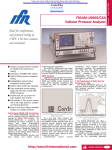
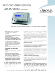
Telecommunications
Digital Communications Analyzer 2841
2 Mbit/s Transmission Analyzer 2840A
Hand-held, high
capability testing for
2 Mbit/s and data line
systems and equipment
Handheld, battery operated, data
and PCM rate tester
Framed and unframed operation at
2 Mbit/s including n x 64 kbit/s
Data test interfaces:
(2841) RS-232, X.21, V.35,
RS-449 (V.36), codirectional,
contradirectional
G.821, G.826, M.2100 analysis
Histograms for error distribution
and alarms
Print from up to 10 results stores
Analog channel generation and
measurement
Measurements include propagation
delay, output level attenuation,
frequency deviation, frequency and
level measurement, and CAS
generated and received to enable a range
of tests on framing, alarms and signaling.
GENERAL
The 2840A 2 Mbit/s Transmission Analyzer is a hand-held analyzer for installation
and maintenance measurements on digital
2 Mbit/s lines and equipment. The 2841
Digital Communications Analyzer adds data
interface testing to this 2 Mbit/s capability.
The
comprehensive
measurement
capability is contained in a compact,
battery operated package, combined with a
large graphics based LCD for ease of set up
and results retrieval.
Modes
Both synchronous and asynchronous
modes as possible with a wide range of
standard and user programmable data
rates, so that traditional data interface
testing can be addressed together with
modern digital data services at 64 kbit/s, n
x 64 kbit/s and other rates.
FRAMING SYSTEMS
2 Mbit/s framing systems with 30 and
31 channels, with and without CRC4, are
56 kbit/s and 64 kbit/s Channel
Testing
Individual channels can be tested at 64
or 56 kbit/s, assisting in testing and fault
location within digital data networks and
cross connect switches.
n x 64 kbit/s Channel Testing
n × 64 kbit/s channels can be tested
where they are carried within 2 Mbit/s
digital signals. Full flexibility is provided
with both contiguous and non-contiguous
channel selection.
DATA INTERFACE TESTING (2841)
All commonly used data interfaces are
available to give a comprehensive data test
capability together with 2 Mbit/s testing.
Thus 2 Mbit/s and data circuits and
equipment can be tested in a hand-held,
fully integrated test instrument. Data test
interfaces provided are RS-232, X.21,
V.35, RS-449 (V.36), codirectional and
contradirectional.
DATA MULTIPLEX TESTING (2841)
Independent transmitter and receiver
enable connection to data and 2 Mbit/s
interfaces simultaneously.
This allows
testing across a data multiplex to ensure
integrity of data card to 2 Mbit/s path.
COMPREHENSIVE ERROR AND ALARM
MEASUREMENTS
The 2840A and 2841 can detect
simultaneously, Code, Framing, Pattern
and CRC Errors. Further measurements
are then made on a selected error type,
including G.821, G.826, M.2100 and error
distribution.
Error Distribution and Alarm
Histograms
The error results and alarms are displayed in the form of a histogram with
accumulation up to 7 days, and resolution
up to 1 second.
This provides a
comprehensive record of long term
measurements to assist in fault localisation. A permanent record of these results
can be obtained by printing a text
equivalent or a facsimile of the histograms
subsequent to the test.
Full Results Printing - Print from RAM
The instrument can be programmed to
Autoprint selected parameters from the full
set, on event or on timed intervals.
These include errors, performance
parameters, and alarms.
Alternatively up to 4000 print events per
results store can be stored in memory
(Print from RAM) for subsequent printing.
This also removes the necessity of real
time printing where subsequent analysis
via a PC may prove this to be unnecessary.
G.821, G.826 and M.2100
Measurements
The usual ITU-T recommendation of
G.821 for 64 kbit/s error performance
measurement is applied. In addition the
newer Recommendation G.826 extends
measurements to 2 Mbit/s, while M.2100
http://www.ifrinternational.com
2841/2840A
1
2841/2840A
MULTIPLE TEST STORAGE
Up to 8 full sets of results can be stored
for later on screen analysis or printing.
Again this can avoid real time printing.
RESIDUAL BIT ERROR RATE
Assessment of background error performance is useful in systems subject to
degraded error performance, such as radio
or satellite systems. RBER is long term
mean error rate ignoring Severely Errored
Seconds.
HIGH TOLERANCE TO BURST ERRORS
2840A and 2841 are particularly suited
to measurements on systems subject to
high error rates and burst errors, with the
ability to ride through rapid fades as
experienced on digital radio systems.
PROGRAMMABLE ERROR GATING
In addition to long term mean error
ratio, a current error ratio is available with
fixed gating periods of 1, 2, 5 or 10
seconds. Flexibility of application is thus
assured, for example fade margin
adjustment on digital radios.
IN-SERVICE AND OUT-OF-SERVICE
MEASUREMENTS
The instrument is equally suited to
installation and maintenance measurements. Interfaces are provided to enable
the receiver to be connected to a number
of network points at varying impedances
and sensitivities. Automatic line equalization (automatic line build out, ALBO) is also
provided to enable connection to signals
attenuated by long sections of line.
IN-SERVICE CHANNEL ACCESS
Access is provided to receive timeslots
for both analog and digital signals.
Voice Channels
Voice channels within a 2048 kbit/s
signal can be monitored in-service and
routed to an internal loudspeaker or a
headphone socket for a first level check of
analog level and quality.
Data Channels
64 kbit/s data channels can be routed
to a V.11 interface for external measurement, for example connection of common
channel signaling to a protocol analyzer.
Drop and Insert
Selected 64 or n x 64 kbit/s channels
within an in-service 2048 kbit/s signal can
be tested with minimum disruption of
service to other in-traffic channels.
NETWORK EQUIPMENT TESTING
Comprehensive facilities enable the
range of applications to be extended
beyond digital link error performance
testing to checking the functionality of
various types of network equipment such
as multiplexes and cross connect switches.
Multiplex Equipment
2840A and 2841 are able to simulate
and detect alarm conditions associated
with the various 2048 kbit/s frame
structures, including full frame alignment
strategy testing to G.706.
In addition the input level margin of the
multiplex can be checked using the output
2
2841/2840A
level attenuation capability whilst
frequency margin can be checked using
the output frequency offset capability.
Cross Connect Switches
Cross Connect switches can be checked
for switch path integrity using the 64 kbit/s
channel test capability (or n × 64 kbit/s for
new generation switches).
ANALOG CHANNEL MEASUREMENTS
Analog measurements are made on
selected 2 Mbit/s channels including
frequency response and linearity. The
transmitter can generate sine waves across
the full audio band with frequency and level
resolution of 1 Hz and 0.1 dB respectively.
Measurements are made of peak code,
RMS level and frequency.
PROPAGATION DELAY MEASUREMENT
Delay measurements can be made on
2048 kbit/s digital circuits to a high level of
accuracy. This is particularly important on
satellite links where high values of delay
are experienced and need to be measured,
or for characterising networks to assist in
finding unwanted loopbacks.
Where data circuits are extended from
2048 kbit/s bearers out to subscribers, the
overall network to subscriber loop delay
can be measured at 64 or n x 64 kbit/s
from within the 2048 kbit/s signal.
CHANNEL ASSOCIATED SIGNALING
The 4 bit word associated with a
selected channel can be controlled on the
transmitter.
On the receiver all 30
channels can be monitored simultaneously.
In addition for a selected channel the last
16 signaling word changes can be stored
for later analysis.
DIGITAL SIGNAL LEVEL AND
FREQUENCY MEASUREMENT
The frequency and amplitude of the
incoming digital signal are displayed to
enable early warning of degradation of the
signal, or to check the loss of in-station
cabling to ensure it conforms to limits.
BIT SLIP DETECTION
Single, uncontrolled bit slips can be
detected within framed or unframed test
patterns.
This allows inter and intra
network clocking problems to be isolated.
OCTET SLIP DETECTION
Octet slips can be detected at the
64 kbit/s channel level of a 2048 kbit/s
signal, which allows the effects of frame
slips introduced by network buffers to be
assessed.
EASE OF USE
The instrument is set up quickly and
easily using graphics based menu selection
on a large LCD, with key pad and soft keys.
Commonly used instrument configurations
can be stored in memory further ensuring
ease of use.
RS-232 REMOTE OPERATION
Remote unattended operation can be
accomplished via an RS-232 port, which
can also be used for local printing.
Keyboard functions can be duplicated via
RS-232 commands enabling complete
remote configuration and reporting of
results.
POWER OPTIONS
Internal batteries give five hours
operation when both transmitter and
receiver are being used. Battery life is
extended in monitoring applications where
the transmitter can be switched off. Fast
charge circuits coupled with an AC power
adaptor enable recharge in only three
hours.
For extended operation the AC power
adaptor can be used with the batteries as
standby in the event of power failure.
Specification
2 Mbit/s Transmit Interface
FRAMING AND BIT RATES
Signals can be transmitted unframed or with the
frame structure indicated.
2048 kbit/s - G.704
2048 kbit/s - G.704 no multiframe
2048 kbit/s - G.704 with CRC
2048 kbit/s - G.704 with CRC, no multiframe
2048 kbit/s - 32 frame multiframe (Option 02,
French)
CLOCK SOURCE
Internal, external or derived from the received signal
Internal
Accuracy
±1 ppm from 0° C to 55° C
±1 ppm / year
Frequency Offset
Small
Steps of ±5 and ±50 ppm to ±150 ppm
Large
Steps of ±2 and ±10 kbit/s to ±30 kbit/s
External
TTL
Sine wave
G.703 Figure 21
LINE CODES
AMI (50% duty cycle)
HDB3
TEST PATTERNS
Insertion
Single Channel
Selected 56 kbit/s or 64 kbit/s channel of framed
signal
Channel Broadcast
All 56 kbit/s or 64 kbit/s channels of framed signal
n × 64 kbit/s Channel
Selected n × 56 kbit/s or n × 64 kbit/s channels of
framed signal
Channel distribution can be contiguous or noncontiguous
Unframed
Unframed signal
PRBS
26-1
29-1
211-1
215-1
220-1
223-1
Sense
True or Inverted
Mode (framed only)
8 bit
PRBS data fills all 8 bits in an octet, ie
64 kbit/s per channel
7 + 1 bit First 7 bits are PRBS and last bit is a 1,
ie 56 kbit/s per channel
32 bit word
User programmable sequence of 32 bits
(16 bit word for Option 02, French)
http://www.ifrinternational.com
Variable Sine Wave
(option 04 on 2840A)
Frequency Range
1 to 3999 Hz
Resolution
1 Hz
Level
+3 to -55 dBm0
Resolution
0.1 dB maximum.
Coding
A-Law
Signaling multiframe alignment strategy.
Set x in 2 consecutive multiframe words in error,
single shot or continuously
FILL PATTERNS
For 64 or n × 64 kbit/s operation the following
patterns are used to fill all other channels
ACCESS TO STRUCTURE BITS
Change unassigned, distant, distant multiframe and
alarm bits.
Time Slot 16 (Signaling).
Set to AIS (All 1s).
Set to All 0s.
2 Mbit/s Receive Interface
PRBS
215-1
8 bit word
User programmable sequence of 8 bits
DROP & INSERT
For framed operation the received signal is looped to
the transmitter
Note that for CRC frame structures the CRC is
recalculated before transmission
56 kbit/s or 64 kbit/s
A selected 56 kbit/s or 64 kbit/s channel is
replaced by a test pattern.
n × 56 kbit/s or n × 64 kbit/s
A selected n × 56 kbit/s or n × 64 kbit/s channel is
replaced by a test pattern. The channel selection
can be contiguous or non-contiguous.
REGENERATOR LINE CURRENT LOOPTHROUGH
Line current on balanced lines can be looped
through from receiver to transmitter of the
instrument.
ERROR INJECTION
Target
Test Pattern Only
Framing Only
CRC Only
All
FRAMING AND BIT RATES
Signals can be received unframed or with the frame
structure indicated.
As Transmitter.
Frequency Tolerance
2048 kbit/s
±50 ppm
LINE CODES
As Transmitter.
Indication of HDB3 signal present
AUTOCONFIGURE
The receiver can be set to autoconfigure to:
2 Mbit/s framed test pattern or unframed test
pattern.
64 kbit/s channel test pattern (channel search or
known channel).
n × 64 kbit/s channel test pattern (known channel).
INPUT MODES AND SENSITIVITY
Modes
Terminated
Bridging
Terminates the line.
Taps onto a terminated line or
unprotected monitor point.
Connects to a protected monitor
point.
Monitoring
Error Type
Binary
Bits are inverted before coding.
Code
Code errors are injected by changing ±1 to 0 and
0 to ±1 where the polarity of the inserted mark is
the same as the polarity of the last mark
transmitted.
Injection Mode
Singly
By keypress
Fixed rate
Rate M x 10-N, where M is 1 to 9 and N is 2 to 7
MAIN OUTPUTS
BALANCED
Impedance
Normal
ALBO
120 Ω
3 V ±0.3 V
0 V ±0.3 V
Unbalanced
Impedance
Peak Voltage
Space Voltage
75 Ω
2.37 V ± 0.237 V
0V ± 0.237 V
Impedance
ALBO
Output Level Attenuation
Attenuation
6 and 10 dB
Accuracy
±0.5 dB
SIGNALING BIT CONTROL
For framing systems with Channel Associated
Signaling capability the signaling bits can be
changed.
Selected Channel
Set 4 bit word.
All Other Channels
Set 4 bit word.
C-BIT FRAMING
(Option 02, French)
Generation of C-Bit Frame for French TRANSMIC-2G
System.
Control of C-Bit Frame message bits.
FRAMING TESTS
The following tests are available, depending on the
framing system selected:
Frame alignment strategy
Set x in 4 consecutive frame words in error, single
shot or continuously
Set x in 3 consecutive frame bits in error, single shot
or continuously
Set x in 4 consecutive CRC multiframe words in
error, single shot or continuously
Set x in 1000 CRC blocks in error continuously
(default value is 915).
Bridging
>1000 Ω
3V
3V
+2 to -6 dB +2 to -6 dB
3V
+2 to -30 dB
Monitor
120 Ω
(3000 Ω)
3V
-15 to -36 dB
UNBALANCED
Normal
Balanced
Impedance
Peak Voltage
Space Voltage
Terminated
120 Ω
Terminated
75 Ω
Bridging
>1000 Ω
2.37 V
2.37 V
+2 to -6 dB +2 to -6 dB
2.37 V
+2 to -30 dB
Monitor
75 Ω
(2400 Ω)
2.37 V
-15 to -36 dB
TEST PATTERNS:
Source
Selected single, contiguous, non-contiguous
channels of framed signal.
Unframed signal.
PRBS
26-1
29-1
211-1
215-1
220-1
223-1
Sense
True or Inverted
Mode (framed only)
8 bit
PRBS data fills all 8 bits in an octet, ie
64 kbit/s per channel
7 + 1 bit First 7 bits are PRBS and last bit is a 1, ie
56 kbit/s per channel
Repetitive Word
Any word which repeats over a 32 bit sequence.
(16 bit sequence for Option 02, French)
PATTERN SYNCHRONIZATION
Loss Criterion
PRBS error rate greater than 1 in 5 for each of 10
consecutive desciseconds.
CHANNEL EXTRACT
For framed single channel operation a selected
64 kbit/s channel is extracted from the received
signal:
Channel selection by increment and decrement keys
Voice frequency signals are routed to the internal
loudspeaker, audio output socket, or headphone
socket.
64 kbit/s data signals are output via a V.11
socket.
AUDIO CHANNEL MEASUREMENT
(option 04 on 2840A)
Frequency, Level, Peak code
Frequency
Range
1 to 3999 Hz
Resolution
1 Hz
RMS Level
Range
+6 to -60 dBm0
Resolution
0.1 dB maximum
Peak code
Positive and negative values
are displayed.
Decoding
A-Law
Telecommunications
2841/2840A
VOICE FREQUENCY OUTPUT
(opt 04 on 2840A)
Range
0.3 to 3400 Hz
Decoding
A-Law
Impedance
600 Ω balanced
STATUS INDICATORS
LEDs indicate frame structure alarm conditions
Display modes
CURRENT ALARMS
Red LEDs illuminate to indicate alarm presence
and extinguish when the condition clears. LEDs
respond to alarm conditions with a resolution of
one second.
HISTORY
When ALARM HISTORY is pressed the CURRENT
ALARM LEDs indicate alarms which have
illuminated since the last time the history reset
button was pressed. RESET resets the ALARM
HISTORY.
SIGNAL GOOD
Green LED illuminates to show absence of
combination of LINE, AIS, FRAME, MF, CRC and
PATTERN alarms.
LINE
Red LED ON indicates signal loss.
AIS
Red LED ON indicates signal is all 1’s. All 1’s is
defined as signal with less than three zeros in two
frame periods.
FRAME
Red LED ON indicates a loss of frame alignment.
CRC MF
Red LED ON indicates loss of CRC multiframe
alignment.
CAS MF
Red LED ON indicates loss of signaling multiframe
alignment.
DISTANT
Red LED ON indicates DISTANT alarm.
DMR
Red LED ON indicates Distant Multiframe Alarm.
PATTERN
Red LED ON indicates loss of pattern
synchronisation.
ERROR RATE
Red LED ON indicates that the error rate of the
major error type is greater than a threshold set by
the user. Threshold is 1 x 10-N where N is 2 to 9.
ERRORS
Red LED ON indicates major errors detected.
Additional Display Indicators
(Auxiliary Alarms Page)
HDB3 SIGNAL
Present or Not Present
TS16 AIS
Present or Not Present
UNASSIGNED FRAMING BITS
The state of the unassigned bits is displayed.
Data Test Interfaces (2841)
X.21, RS-449 (V.36), V.35, RS-232,
Co/Contradirectional and TTL
X.21, RS-449 (V.36), V.35, RS-232 and
Co/Contradirectional
X.21 (V.11), RS-449 (V.11), V.35, RS-232 and
Co/Contradirectional are presented to a common
connector. DTE/DCE interfaces are provided by
adaptor cables which provide the appropriate
connector and electrical interface. The DTE/DCE
switching is internal.
Universal Connector
68 way type PCR female.
http://www.ifrinternational.com
2841/2840A
3
2841/2840A
Adaptor Cable Connectors
X.21
15 way D-Type, ISO 4903 female.
RS-449 (V.36)
37 way D-Type, ISO 4902 female.
V.35
34 way MRAC, ISO 2593 female.
RS-232
25 way D-Type, ISO 2110 female.
Co/Contradirectional
15 way D-Type, ISO 4903 female.
Codirectional
CF x 2 female.
IMPLEMENTATION
X.21, RS-449 (V.36), V.35, RS-232
DTE.
DCE.
Cable recognition
Automatic recognition of the cable type plugged in.
TTL
Code
Connector
NRZ
Miscellaneous 25 way D-Type
CONTROL LINES
X.21
DTE
I (Indication)
C (Control)
RS-449 (V.36)
DTE
CS (Clear to
send)
RS (Request to
send)
DTR (Data
terminal ready)
DSR (Data set
ready)
DCE
C (Control)
I (Indication)
DCE
RS (Request
to send)
CS (Clear to
send)
DSR (Data set
ready)
DTR (Data
terminal ready)
DCD (Data
Carrier Detect)
DCD (Data
Carrier Detect)
V.35
DTE
CS (Clear to
send)
RS (Request to
send)
DTR (Data
terminal ready)
DSR (Data set
ready)
RTS (Request
to send)
DTR (Data
terminal ready)
Displayed as 1, 0
Settable to 1, 0
Settable to 1, 0
Displayed as 1, 0.
Settable to 1, 0.
Displayed as 1, 0.
DCE
RS (Request
to send)
CS (Clear to
send)
DSR (Data set
ready)
DTR (Data
terminal ready)
DCD (Data
Carrier Detect)
DCD (Data
Carrier Detect)
RS-232
DTE
CTS (Clear to
send)
DSR (Data set
ready)
RLSD (Receive
line signal detect)
TM (Test mode)
Displayed as 1, 0.
Settable to 1, 0
Displayed as 1, 0.
Settable to 1, 0
Settable to 1, 0.
Displayed as 1, 0.
Settable to 1, 0.
Displayed as 1, 0.
DCE
RTS (Request
to send)
DTR (Data
terminal ready)
LL (Local loop)
RL (Remote
loop)
CTS (Clear to
send)
DSR (Data set
ready)
RLSD (Receive
line signal
detect)
TM (Test mode)
LL (Local loop)
RL (Remote loop)
Displayed as 1, 0.
Displayed as 1, 0.
Displayed as 1, 0.
Displayed as 1, 0.
Settable to 1, 0
Settable to 1, 0
Settable to 1, 0.
Settable to 1, 0.
Set to 1 for V.54
selected
Set to 0 for V.54
deselected
Set to 1 for V.54
selected
Set to 0 for V.54
deselected
MODE
Synchronous
X.21, RS-449 (V.36), V.35, RS-232, TTL
Asynchronous
RS-449 (V.36), RS-232
loop 3
loop 3
loop 2
loop 2
Electrical
X.21
V.11 (balanced)
RS-449 (V.36)
V.11 (balanced)
V.35
V.35 (data and timing)
V.28 (control lines)
RS-232
V.28
Input Impedance
X.21, RS-449 (V.36)
V.11 Terminated
120 Ω
V.11 Unterminated
>3000 Ω
V.35
100 Ω
Data Rate
X.21, RS-449 (V.11) (Sync)
50 bit/s to 2.5 Mbit/s
V.35 (Sync)
50 bit/s to 2.5 Mbit/s.
RS-232 (Sync)
50 bits/ to 80 kbit/s
RS-232, RS-449 (Async)
50 bit/s to 38.4 kbit/s
TTL
50 bit/s to 2.5 Mbit/s
Timing
Synchronous
Transmit - DTE
From DCE
DCE input timing.
Internal
1 bit/s steps.
Receiver
Receiver clock (assumes receiver is data interface,
not 2048 kbit/s, and same rate as transmitter)
External
TTL input.
Transmit - DCE
Internal
1 bit/s steps.
Receiver
Receiver clock
External
TTL input.
Receive - DTE
From DCE
DCE input timing
External
TTL input.
Signal
Extracted from receive signal
Receive - DCE
From Transmitter
Transmit clock (assumes transmitter is data
interface, not 2048 kbit/s, and same rate as
receiver)
External
TTL input.
Signal
Extracted from receive signal.
DTE
From DTE
Transmit - TTL
Internal
1 bit/s steps.
Receiver
Receiver clock (assumes receiver is TTL interface,
not 2048 kbit/s, and same rate as transmitter).
External
TTL input.
Receive - TTL
External
TTL input.
Signal
Extracted from receive signal.
From Transmitter
Transmit clock.
All input and output timing signals can be inverted in
polarity.
Asynchronous
Transmit
Internal
50, 75, 100, 110, 134.5, 200, 600, 1200,
1800, 2000, 2400, 3600, 4800, 7200, 9600,
14400, 19200, 38400 bit/s.
Receive
Receive signal.
Async coding
Data bits
7, 8.
Stop bits
1, 2.
Parity
Odd, even, mark, space, none.
Async character rate
Transmitter
Selectable: low medium, high, (10, 50 and 100%
maximum character rate).
Receiver
Up to 1000 character/sec.
TEST PATTERNS
Sync and async
PRBS
26-1
29-1
211-1
215-1
220-1
223-1
Sense
True or inverted
Sync
32 bit word
User programmable sequence of 32 bits
Async
Fox message
3 messages to ITU-T
Recommendation R.52.
Fox 1
International alphabet 2.
Fox 2
International alphabet 5, 96
character set
Fox 3
International alphabet 5, 64
character set.
User message 1 to 64 characters.
ERROR INJECTION
Singly
By keypress
Fixed rate
Rate 9 × 10⁻² to 1 × 10⁻⁷ (sync only)
ALARMS
Line
Errors
Pattern
No transmit clock
PROPAGATION DELAY (sync only)
Measured using a PRBS test pattern
Range
Up to 2 seconds
Resolution
1 bit period
Update rate Typically 2 seconds. Can be longer
at low data rates.
TIMING MEASUREMENT (DTE only)
Time intervals between changes of control lines
X.21
C and I
RS-449 (V.36) RS and CS
V.35
RTS and CTS
Range
0 to 10s
Resolution
1 ms
BIT RATE MEASUREMENT
(Transmitter and Receiver)
Measurement of transmitter bit rate confirms DCE
clock rate when DTE, or external clock rate.
Sync
The bit rate is measured every second displayed to
nearest 1 Hz.
Async
The character rate is measured every second
displayed to nearest 1 Hz.
Accuracy
±1 ppm.
Sense
4
2841/2840A
http://www.ifrinternational.com
Line signal coding and level
Bit Rate
Format
Transmit Timing
DTE
DCE
Receive Timing
DTE
DCE
Pinouts
1, 9
3, 11
5, 13
7, 15
4, 12
6, 14
8
Residual Bit Error ratio
(Background Error Rate)
Long Term Mean Error Ratio excluding Severely
Errored Seconds.
Codirectional
To ITU-T Rec. G.703
64 kbit/s
Unstructured
Contradirectional
To ITU-T Rec. G.703
64 kbit/s
Unstructured
Receiver (from DCE)
Internal
External 2048 kbit/s
Internal (to DTE)
External 2048 kbit/s
From DCE
Internal
Receiver External 2048 kbit/s
Internal (to DTE)
External 2048 kbit/s
Extracted from receiver signal (from DCE)
Extracted from receiver signal (from DTE)
Extracted from receiver signal
Internal (to DTE) External 2048 kbit/s
Transmit Data
Receive Data
Transmit Data
Receive Data
Transmit Clock In (from DCE)
Receive Clock In (from DCE)
Transmit Clock Out (to DTE)
Receive Clock Out (to DTE)
Earth
Earth
X.21 -DTE/DCE
Pins
4,11
6, 13
5, 12
7, 14
Pins
2, 9
3, 10
8
From DTE (To DCE)
Transmit
Control
Ground
Circuit
T
C
Pins
4,22
17,35
19
7,25
12,30
From DTE (To DCE)
SD Send Data
TT Tx Timing
Signal Ground
RS (Request To Send)
DTR (Data Terminal Ready)
Pins
P,S
U,W
B
C
H
From DTE (To DCE)
Transmit Data
Transmit Timing
Signal Ground
Request to send
DTR (Data Terminal Ready)
105
108/2
Pins
2
24
4
20
18
21
7,1
From DTE (To DCE)
Transmit data
Transmit timing
Request to send
Data terminal ready
Local loop
Remote loop
Ground
RS-232 - DTE/DCE
Circuit
Pins
103
3
113
17
105
15
108
5
141
6
140
8
25
Pins
1
2
3
4
5
6
7, 19
8, 20
9
TTL (Miscellaneous connector)
Pins
Power Feed Loopthrough A
10, 22
64 kHz clock out (V.11)
Power Feed Loopthrough B
11, 23
64 kHz data out (V.11)
Receive 2 Mbit/s or Data clock out
12, 13
Audio out (600 Ω)
Transmit 2 Mbit/s or Data clock out
14
Receive 2 Mbit/s or Data clock in
Transmit 2 Mbit/s or Data clock out
15
Transmit 2 Mbit/s or Data data in
Transmit external clock in
16, 17, 18
Earth
8 kHz frame clock out (V.11)
21, 24, 25
Earth
Octet market out (V.11)
N/C
RS-449 (V.36) - DTE/DCE
Circuit
Pins
103
6,24
113
8,26
5,23
105
9,27
108/2
11,29
13, 31
Circuit
103
113
V.35 - DTE/DCE
Pins
R,T
V,X
Y,AA
D
E
F
Measurements
ERROR TYPES
Line Code (Bipolar Violations)
Frame Bit
Frame Word
Pattern
CRC
(Pattern errors only for data test interfaces)
Main parameters:
Made if the framing system and Test Mode allow.
Number of Errors.
Long Term Mean Error Ratio (LTMER).
Total Test Time.
Number of Loss of Signal (LOS) seconds.
Number of AIS seconds.
Number of No Frame Alignment seconds.
Number of No Pattern Sync seconds.
Number of No CRC Sync seconds.
To DTE (From DCE)
Receive
Timing
Indication
Byte Timing
Circuit
R
S
I
B
To DTE (From DCE)
RD Receive Data
RT Rx Timing
ST Send Timing
CS (CTS)
DSR (Data Set Ready)
DCD (Data Carrier Detect)
Circuit
104
115
114
106
107
109
To DTE (From DCE)
Receive data
Receive timing
Transmit timing
Clear to send
DSR (Data Set Ready)
DCD (Data Carrier Detect)
Circuit
104
115
114
106
107
109
To DTE (From DCE)
Receive data
Receive timing
Transmit timing
Clear to send
Data set to ready
Receive line signal
Test mode
Circuit
104
115
114
106
107
109
142
OCTET SLIPS
Octet Slips are detected for single channel pattern
measurements:
Number of positive and negative slips.
Time of last slip.
Time between last two slips.
BIT SLIPS
Single bit slips are detected within a 64 or
n × 64 kbit/s test pattern within a 2 Mbit/s signal,
an unframed 2 Mbit/s test pattern, or an unframed
test pattern via one of the data test interfaces.
Positive and negative bit slips are counted.
(Bit Slips and Octet Slips are mutually exclusive).
ADDITIONAL PARAMETERS
Current Error Ratio
Gating
1, 2, 5 or 10 seconds.
G.821 ERROR PERFORMANCE MEASUREMENTS
64 kbit/s channel availability measurements are
made to ITU-T Recommendation G.821, while for
higher rates a channel performance to G.821 Annex
D is applied.
Parameters
% Available Time.
Number of Errored Seconds.
% Error Free Seconds.
Number of Severely Errored Seconds (SES).
% Non SES.
Number of Degraded Minutes (DM).
% Non DM.
Number of Breaks.
The inverse % parameters are also available.
User programmable thresholds for %ES (%Errored
Seconds), %SES (%Severely Errored Seconds), %DM
(%Degraded Minutes) and %US (%Unavailable
Seconds). Exceeding the threshold during a test
causes message. Threshold activation settable for
each parameter YES/NO.
Parameter
%ES
%SES
%DM
%US
Limit
XX.XXXX
XX.XXXX
XX.XXXX
XX.XXXX
Telecommunications
2841/2840A
Message
%ES > limit
%SES > limit
%DM > limit
%US > limit
X=1 to 9
M.2100
Implementation of Interpretation for the Receive and
Send Direction columns in Table B2/M.2100 for 2
Mbit/s signal (non CRC4) and 2 Mbit/s (CRC4).
User programmable thresholds S1 and S2 for ES
(Errored Seconds), SES (Severely Errored Seconds)
and US (Unavailable Seconds). Exceeding the
threshold during a test causes message. Threshold
activation settable for each parameter YES/NO.
Parameter S1
Limit
ES
XXXX
S2
Limit
XXXX
SES
XXXX
XXXX
US
XXXX
XXXX
Message
ES >S1 limit or
ES > S2 limit
SES > S1 limit or
SES > S2 limit
US > S1 limit or
US > S2 limit
X=1 to 9
G.826
Parameters
Number of Errored Blocks (EB).
Number of Errored Seconds (ES).
Number of Severely Errored Seconds (SES).
Number of Background Block Errors (BBE).
Errored Second Ratio (ESR).
Severely Errored Seconds Ratio (SESR).
Background Block Error Ratio (BBER).
Unavailable Seconds (US).
% Unavailable Seconds (%US).
% Available Seconds (%AS).
Number of Breaks.
User programmable thresholds for ESR (Errored
Seconds Ratio), SESR (Severely Errored Second
Ratio), BBER (Background Block Error Ratio) and
%US (% Unavailable Seconds). Exceeding the
threshold during a test causes message. Threshold
activation settable for each parameter YES/NO.
Parameter
ESR
SESR
BBER
%US
Limit
X.XE-Y
X.XE-Y
X.XE-Y
X.XXXX
Message
ESR > limit
SESR > limit
BBER > limit
%US > limit
X=1 to 9, Y=2 to 8
PROPAGATION DELAY
Measured using a PRBS test pattern.
Mode
2048 kbit/s unframed.
64 kbit/s channel within 2048 kbit/s signal.
n × 64 kbit/s channel within 2048 kbit/s signal.
Range
Up to 2 seconds
http://www.ifrinternational.com
2841/2840A
5
2841/2840A
C-BIT FRAMING
Resolution
1 µs or 1 bit whichever is the greater
(Option 02, French)
Monitoring of C-Bit Frame for French TRANSMIC-2G
System.
Display of C-Bit Frame message bits.
Update rate
Typically 2 seconds.
STORED RESULTS
Storage Capacity
Up to 4,000 events per results store including errors
and alarms stored with a time and date stamp to a
resolution of 1 second.
Multiple Tests
8 full sets of results stored.
Results Retrieval
Print to external printer.
Selected results histograms.
Mark portion of histogram and print selection of
errors, alarms and periodic results between marks.
Error and Alarm Distribution Histograms
Any one of the following parameters can be selected
as the histogram display:
Parameters
Major Errors
Errored Seconds
Severely Errored Seconds
Degraded Minutes
Unavailability
Breaks
Loss of Signal
AIS
Loss of Frame Alignment
Loss of Pattern Synchronisation
Range
+3 to -10 dB
±1 dB
-10 to -20 dB
±2 dB
-20 to -36 dB
±3 dB
SET UP
Copy facility from Transmitter to Receiver and
Receiver to Transmitter.
Histogram page width
7 or more days with a resolution of 1 day.
30 hours with a resolution of 1 hour.
30 minutes with a resolution of 1 minute.
30 seconds with a resolution of 1 second.
The display is selectable from anywhere within the N
days.
Display
The stored results are displayed as a histogram. A
cursor is moved to point at any day, hour, minute or
second. The number of events for the parameter
selected for that interval are displayed together with
the date and time.
Histogram Baseline Alarms
Alarms history is shown by histogram baselines.
Totals for each alarm can be determined by
displaying as the main histogram with cursor
scrolling and reading of alarm totals for each
interval.
signal
Frame Alignment
Pattern Synchronization
Power (not available on the main histogram)
TEST TIMING
Start time
YYYY, MM, DD, HH, MM (year, month, day, hour,
minute).
By keypress
Stop time
YYYY, MM, DD, HH, MM (year, month, day, hour,
minute).
By keypress.
Duration
DD, HH, MM (days, hours, minutes)
Indefinite.
SIGNALING ANALYSIS
Channel associated signaling analysis for selected
channel.
Display:
Decimal and binary equivalent of current and
previous
16 signaling codes.
Signaling code for all 30 channels simultaneously,
with programmable IDLE and BUSY display.
2841/2840A
DIGITAL SIGNAL VOLTAGE MEASUREMENT
The amplitude of the incoming digital signal is
measured and displayed in Volts base-to-peak
and dB relative to nominal.
General Characteristics
Accumulation time
Typically 7 days or better
6
Accuracy
±1 ppm.
OPERATOR INTERFACE
The instrument is controlled via a keyboard
containing a data entry keypad. The 24 line 42
character (plus graphics capability) LCD and
keyboard are fully interactive providing menu and
soft-key operation.
Resolution
1 second, 1 Minute, 1 Hour, 1 Day
Alarms
Loss of
AIS
Loss of
Loss of
Loss of
BIT RATE MEASUREMENT
The received bit rate is measured every second
displayed to nearest 1 Hz.
DISPLAYS
Transmit parameters
Receive parameters
Measurement results
RS-232C port parameters
Printer type selection
Measurement definition
Autoprint definition
Setup conditions (Stored Parameters)
Current status
Zoom
Selected results can be displayed in zoom mode
with large character size.
AUDIBLE ALARM
Mode
When on alarm sounds on detection of:
A signal alarm.
An errored second.
LOUDSPEAKER
Selected 64 kbit/s channels can be routed to the
loudspeaker. There is a volume control.
SETUP CONDITIONS (STORAGE FACILITY)
A variety of information can be stored in non-volatile
memory (battery backed-up).
Setup Conditions
6 sets of transmitter/receiver/test definition
parameters can be selected for storage. Each set
can be recalled whenever required, and can be
identified with a 12 character label. In addition 13
non-alterable standard setups are available:
Unframed Transmitter and Receiver
30 Channel n × 64 kbit/s
31 Channel n × 64 kbit/s
30 Channel n × 64 kbit/s with CRC4.
31 Channel n × 64 kbit/s with CRC4.
30 Channel n × 64 kbit/s, Drop and Insert
31 Channel n × 64 kbit/s, Drop and Insert
30 Channel n × 64 kbit/s with CRC4, Drop and
Insert
31 Channel n × 64 kbit/s with CRC4, Drop and
Insert
30 Channel Monitor Live Traffic.
31 Channel Monitor Live Traffic.
30 Channel with CRC4 Monitor Live Traffic.
31 Channel with CRC4 Monitor Live Traffic.
KEYBOARD LOCKOUT
The keyboard can be disabled whilst a test is
running.
PRINTER OPERATION
The RS-232 port is used for printer operations and
remote control
Printers
40 column minimum, RS-232 interface
Page Printing
Page printouts are initiated by the PRINT key and
cause the whole of the current page to be printed.
Graphics display pages can be printed in a text
equivalent or a facsimile to a suitable printer.
Autoprinting
The printer can be set to print automatically on the
occurrence of any of the following (where
applicable), each event printed with its date and
time and two digit identity number. A twelve
character label is also printed where appropriate:
Test start and stop.
Loss and restoration of signal.
Loss and restoration of alignment.
Loss and restoration of pattern sync.
Detection of errors (ES).
Detection of alarms.
Detection of octet slips.
Detection of short term (current) error ratio, for the
selected major error type, crossing a user set
threshold.
Detection of change of signaling code.
Cumulative printout at user selectable intervals,
with a resolution of 15 minutes.
All stored results may be included in the interval
print.
User selectable.
Loss and restoration of power.
REMOTE CONTROL
The RS-232 port is used for Remote configuration
and collection of results.
RS-232 PORT
The RS-232 port is used for printer operations and
remote control.
Type
Asynchronous
DTE
Full Duplex
Bit Rates
300, 600, 1200, 2400, 4800 and 9600 bit/s.
Code
ASCII
Code bits. Parity/Stop bits
7/Odd/1, 7 /Even/1, 7/Odd/2, 7/Even/2, 8/None/1,
8/None/2
Terminator
None, CR, LF, CR \ LF.
Handshake
Hardware
DTR, RTS, CTS and DSR.
Software
XON and XOFF.
Lines used
Tx DATA
RTS
DTR
Rx DATA
CTS
DSR
Signal Ground
Pin
Pin
Pin
Pin
Pin
Pin
Pin
3
7
4
2
8
6
5
Connector
9 way female D-type
Electrical
To RS-232C / V.28
DISPLAY LANGUAGES
English, French
LIMIT RANGE OF OPERATION
REAL TIME CLOCK
Displays date and time.
Temperature
0 to 55°C (Display specified to 50°C)
Resolution
One second
Safety
Complies with IEC 1010-1, BS EN61010-1 for class
3 hand-held equipment and is for use in a pollution
degree 2 environment. The instrument is designed
to operate from an installation category 1 supply.
Accuracy
±1 minute per week.
http://www.ifrinternational.com
CONDITIONS OF STORAGE AND TRANSPORT
Versions and Accessories
Temperature
-40 to +70°C
When ordering please quote full ordering number
information.
Humidity
Up to 90% relative humidity (non condensing)
Ordering
Numbers
2841
2840A
Altitude
Up to 2500 m (pressurized freight at 27 kPa
differential)
ELECTROMAGNETIC COMPATIBILITY
Conforms to the protection requirements of Council
Directive 89/336/EEC.
Complies with the limits specified in the following
standards.
BS EN55011 Class B CISPR 11.
BS EN55082-1.
IEC 801-2, 3, 4.
POWER REQUIREMENTS
The instrument is powered by internal batteries
which give a nominal 5 hours operation. This is
extended in receive only mode.
UNIVERSAL AC POWER ADAPTOR
The AC power adapter is capable of powering the
instrument and at the same time recharging the
batteries in 3 hours.
AC Voltage
90 to 264 V.
46662/561
54311/190
54311/191
54311/209
Consumption
20 VA maximum.
DIMENSIONS AND WEIGHT
Height
77 mm
57mm
46882/290
46882/227
46662/560
54311/192
54311/193
54311/194
Frequency
45 to 440 Hz
2841
2840A
Option 01
Option 02
Option 04
Width
206 mm
206mm
Depth
170 mm
170mm
Weight
1.5 kg
1.3kg
54311/211
54311/212
54311/213
54311/214
54311/215
46880/075
54311/190
54311/191
54311/192
54311/193
54311/194
54311/209
54311/211
54311/212
54311/213
54311/214
54311/215
54311/121
54311/122
54311/147
54311/148
54311/130
46662/562
54717/039
54311/217
46662/620
46883/805
54311/210
46662/387
46662/388
46662/564
Versions
Digital Communications Analyzer.
2Mbit/s Transmission Analyzer.
Options
1.6/5.6 connectors.
French key panel, C-Bit frame.
Analog generation and measurement
(2840A only - standard on 2841).
Supplied Accessories
Operating Manual 2841.
Operating Manual 2840A.
Universal AC Power Adapter
(90 - 264V).
Carrying Pouch. One adaptor lead from the
list below selected at time of order (2841).
Adaptor Leads (2841)
One specified lead supplied at no charge.
Additional leads can be ordered from the
list below.
X.21 (V.11) Adaptor Lead, 0.2m, female.
RS-449 (V.11) Adaptor Lead, 0.2m,
female.
V.35 Adaptor Lead, 0.2m, female
RS-232 Adaptor Lead, 0.2m, female.
Co/Contradirectional Adaptor Lead - 15 way
D-Type, 0.2m, female
Codirectional Adaptor Lead - CF
connectors, 0.2m, male.
X.21 (V.11) Adaptor Lead, 2m, male.
RS-449 (V.11) Adaptor Lead, 2m, male.
V.35 Adaptor Lead, 2m, male.
RS-232 Adaptor Lead, 2m, male.
Co/Contradirectional Adaptor Lead - 15 way
D-Type, 2m, male.
Optional Accessories
Service Manual.
X.21 (V.11) Adaptor Lead, 0.2m, female
(2841).
RS-449 (V.36) Adaptor Lead, 0.2m, female
(2841).
V.35 Adaptor Lead, 0.2m, female (2841).
RS-232 Adaptor Lead, 0.2m, female
(2841).
Co/Contradirectional Adaptor Lead - 15 way
D-Type, 0.2m, female (2841).
Codirectional Adaptor Lead - CF
connectors, 0.2m, female (2841).
X.21 (V.11) Adaptor Lead, 2m, male
(2841).
RS-449 (V.11) Adaptor Lead, 2m, male
(2841).
V.35 Adaptor Lead, 2m, male (2841).
RS-232 Adaptor Lead, 2m, male (2841).
Co/Contradirectional Adaptor Lead - 15 way
D-Type, 2m, male (2841).
RS-232 Lead - male to male - 25 Way DType - 1.5m (2841).
X.21 Lead - male to male - 15 way D-Type
- 1.5m (2841).
RS-449 Lead - male to male - 37 way DType - 1.5 m (2841).
V.35 Lead - male to male - 34 Way MRAC 1.5 m (2841).
Co/Contradirectional Test Lead - 15 way DType to free end (2841).
Hard Carrying Case.
Scriptos printer.
RS-232 special lead Scriptos to 2841.
Scriptos paper 10 packs.
Signal lead balanced (CF-CF).
Signal lead unbalanced
(BNC-BNC).
Null Modem (female to male).
BNC to 1.6/5.6 adaptor.
RS-232 adaptor - 9 way male to 25 way
female D-Type.
http://www.ifrinternational.com
2841/2840A
Telecommunications
2841/2840A
7
2841/2840A
IFR Americas, Inc., 10200 West York Street, Wichita, Kansas
67215-8999, USA. E-mail: [email protected]
Tel: +1 316 522 4981 Toll Free USA: 1 800 835 2352 Fax: +1 316 522 1360
IFR Ltd, Longacres House, Norton Green Road, Stevenage, Herts
SG1 2BA, United Kingdom. E-mail: [email protected]
Tel: +44 (0) 1438 742200 Freephone UK: 0800 282 388 Fax: +44 (0) 1438 727601
As we are always seeking to improve our products, the information in this document gives only a general indication of the product capacity, performance and suitability, none of which shall form part of any
contract. We reserve the right to make design changes without notice. All trademarks are acknowledged. Parent Company IFR Systems, Inc. © IFR Ltd. 1999.
8
2841/2840A
http://www.ifrinternational.com
Part no. 46890-047
Issue 1