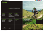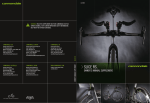
1
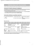
127838
XXXXXXX
CANNONDALE EUROPE
CANNONDALE UK
Cycling Sports Group, Inc.
172 Friendship Road,
Bedford, Pennsylvania, 15522-6600, USA
(Voice): 1-800-BIKE-USA
(Fax): 814-623-6173
[email protected]
Cycling Sports Group Europe, B.V.
mail: Postbus 5100
visits: Hanzepoort 27
7570 GC, Oldenzaal, Netherlands
(Voice): +41 61.4879380
(Fax): 31-5415-14240
[email protected]
Cycling Sports Group
Vantage Way, The Fulcrum,
Poole, Dorset, BH12 4NU
(Voice): +44 (0)1202 732288
(Fax): +44 (0)1202 723366
[email protected]
CANNONDALE AUSTRALIA
CANNONDALE JAPAN
WWW.CANNONDALE.COM
Cycling Sports Group
Unit 8, 31-41 Bridge Road
Stanmore NSW 2048
Phone: +61 (0)2 8595 4444
Fax: +61 (0) 8595 4499
[email protected]
Namba Sumiso Building 9F,
4-19, Minami Horie 1-chome,
Nishi-ku, Osaka 550-0015, Japan
(Voice): 06-6110-9390
(Fax): 06-6110-9361
[email protected]
© 2011 Cycling Sports Group
127838 (11/11)
OWNER’S MANUAL SUPPLEMENT
CANNONDALE USA
SCALPEL 29’ER
WARNING! READ THIS SUPPLEMENT AND YOUR CANNONDALE BICYCLE
OWNER’S MANUAL. BOTH CONTAIN IMPORTANT SAFETY INFORMATION.
KEEP BOTH FOR FUTURE REFERENCE.
SCALPEL 29’ER.
OWNER’S MANUAL SUPPLEMENT.
127838.PDF
SAFETY INFORMATION
Important Composites Message
About This Supplement
Cannondale Owner’s Manual Supplements provide
important model specific safety, maintenance, and
technical information. They are not replacements for your
Cannondale Bicycle Owner’s Manual.
This supplement may be one of several for your bike. Be
sure to obtain and read all of them.
If you need a manual or supplement, or have a question
about your bike, please contact your Cannondale Dealer
immediately, or call us at one of the telephone numbers
listed on the back cover of this manual.
You can download Adobe Acrobat PDF versions of any
Cannondale Owner’s Manuals or Supplements from our
website: http://www.cannondale.com/.
■ This manual is not a comprehensive safety or
service manual for your bike.
■ This manual does not include assembly
instructions for your bike.
■ All Cannondale bikes must be completely
assembled and inspected for proper operation by
a Cannondale Dealer before delivery to the owner.
WARNING
This supplement may include procedures beyond the
scope of general mechanical aptitude.
Special tools, skills, and knowledge may be required.
Improper mechanical work increases the risk of an
accident. Any bicycle accident has risk of serious
injury, paralysis or death. To minimize risk we strongly
recommend that owners always have mechanical
work done by an authorized Cannondale retailer.
WARNING
Your bike (frame and components) is made from composite
materials also known as “carbon fiber.”
All riders must understand a fundamental reality of
composites. Composite materials constructed of carbon
fibers are strong and light, but when crashed or overloaded,
carbon fibers do not bend, they break.
For your safety, as you own and use the bike, you must
follow proper service, maintenance, and inspection of all the
composites (frame, stem, fork, handlebar, seat post, etc.) Ask
your Cannondale Dealer for help.
We urge you to read PART II, Section D. “Inspect For Safety”
in your Cannondale Bicycle Owner’s Manual BEFORE you ride.
YOU CAN BE SEVERELY INJURED, PARALYZED OR KILLED IN
AN ACCIDENT IF YOU IGNORE THIS MESSAGE.
Intended Use
ASTM F2043
For rough
off-road riding
and jumps less
than 24” (61 cm)
The intended use of all models is
ASTM CONDITION 3, Cross-Country,
Marathon, Hardtails.
WARNING
UNDERSTAND YOUR BIKE AND ITS INTENDED USE.
USING YOUR BIKE THE WRONG WAY IS DANGEROUS.
Please read your Cannondale Bicycle Owner’s Manual
for more information about Intended Use and
Conditions 1-5.
11/11
1
Inspection & Crash Damage Of
Carbon Frames/Forks
WARNING
Bicycle Repair / Work Stands
The clamping jaws of a bike stand can generate a crushing
force strong enough to seriously damage your frame.
NOTICE
AFTER A CRASH OR IMPACT:
Never place your bike in a bike stand by clamping the frame.
Inspect frame carefully for damage (See PART II, Section
D. Inspect For Safety in your Cannondale Bicycle Owner’s
Manual. )
Place your bike in a stand by extending the seat post and
positioning the stand clamp on the extended seat post. Don’t
extend beyond the MINIMUM INSERT line marked on the seat
post.
Do not ride your bike if you see any sign of damage, such as
broken, splintered, or delaminated carbon fiber.
ANY OF THE FOLLOWING MAY INDICATE A DELAMINATION OR
DAMAGE:
■
An unusual or strange feel to the frame
■
Carbon which has a soft feel or altered shape
■
Creaking or other unexplained noises,
■
Visible cracks, a white or milky color present in
carbon fiber section
Continuing to ride a damaged frame increases the
chances of frame failure, with the possibility of injury or
death of the rider.
Repainting Or Refinishing
Since your carbon seat post can also be damaged by
clamping force, adjust the stand clamp for the minimum
clamping force needed to secure the bike.
Also, before clamping, clean the post and protect the seat
post finish with a rag.
If you have an old unused seat post, use it instead of your
regular post to mount your bike in a stand.
Tightening Torques
Correct tightening torque for the fasteners (bolts, screws, nuts)
on your bicycle is very important to your safety. Correct tightening
torque for the fasteners is also important for the durability and
performance of your bicycle. We urge you to have your Dealer
correctly torque all fasteners using a torque wrench. If you decide
to torque fasteners yourself always use a torque wrench.
Find Tightening Torque Information
WARNING
Repainting, painting over, retouching, or refinishing
your frame or fork can result in severe damage leading
to an accident. You can be severely injured, paralyzed
or killed.
Refinishing chemicals : Solvents, and strippers can
attack, weaken, or destroy the important composite
chemical bonds holding your frame together.
Using abrasives or sanding the frame/fork structure,
original paint, decals, or coatings through the use
of mechanical actions such as plastic or glass bead
blasting or other abrasive methods such as sanding
or scraping can remove frame material or weaken it.
2
The wide range of bicycle models and components used means that
a listing of tightening torque would be out of date by the time it was
published. Many fasteners should be installed with a thread locking
adhesive such as Loctite®.
To determine correct tightening torque and any adhesive application for
a fastener we ask you to check:
•
Markings on the component. Many components are
marked. On-product marking is becoming common.
•
Torque specs in the component
instructions shipped with your bicycle.
manufacturers
• Torque specs listed on the websites of component
manufacturers.
•
With your Dealer. Dealers have access to current data and
have experience with correct torque for most fasteners.
127838.PDF
WATER BOTTLE & CAGE
4 mm
5 mm
CABLE GUIDE PARTS
M5 SCREWS
3 Nm, (26.5 inLbs)
500cc
WATER BOTTLE
THREADED
INSERTS
SIDE-ENTRY
or
SMALL CAGE
WASHER
■
Select a cage and bottle combination to prevent interference with suspension movement or difficulty in
placing a bottle.
■
Do not use a top-entry cage. Use a side entry bottle cage and a small volume water bottle (500cc). Large
volume bottles are not recommend.
■
The cables guides and the spacer must be positioned between the cage and the frame so the cables run
underneath the cage. The cage screws must be long enough to ensure correct thread engagement with the
frame insert. You may need to obtain longer screws .
■
Side impacts to a water bottle or cage can result in damage threaded inserts due to the leverage on a very
small area. When storing or transporting your bike, take steps to prevent situations where a water bottle may
be hit or bumped by a strong force that would cause damage. Remove bottle and cage when you are packing
your bike for travel.
■
Periodically check the attachment of the bottle cage; tighten the cage bolts if necessary. Don’t ride with a
loose bottle cage. Riding with loose cage bolts can produce a rocking motion or vibration of the attached
cage.
NOTICE
Damage caused by an impact, crash, loose bottle cage, or improper installation is not covered by
the Cannondale Limited Warranty.
3
BOTTOM BRACKET - PRESSFIT BB30
SCALPEL 29’ER CARBON
Carbon frames have a 46 mm I.D. bottom bracket bearing system press interface. The shell width is 73mm.
Maintenance
In general, you should inspect the condition of the bearings annually (at a minimum) or anytime the crankset assembly
is disassembled , serviced, or if a problem is indicated.
To inspect, when the crankset is removed, rotate the inner bearing race of both bearings; rotation should be smooth, and
quiet. Execesssive play, roughness or corrossion indicates a damaged bearing.
Removal
To avoid serious damage to the frame, it is important to remove bearing systems very carefully using proper tools
indicated by the manufacture’s service instructions. Make sure the bearings(cup or adpater parts) are driven out
squarely and evenly from inside the shell!!! Do not pry components from shell.
Replacement
PressFit BB30 bearings are not removable from the adapters or cup systems that are pressed into the frame bottom
bracket shell. Therefore, damaged bearings must be removed and replaced as new entire sets. Before installing any new
bearing units into the shell, thoroughly clean the inside surface of the bottom bracket shell with a clean dry shop towel.
Also, make sure both bearing units and the BB shell surfaces are clean and dry. Do not apply grease to either.
Follow the manufacture’s instruction for assembly and installtion of the bearing system. Use a headset press such as
Park Tool HHP-2. See www.parktool.com/product/bearing-cup-press-HHP-2 Select appropriate press and adapters to
ensure that force is only applied to the cup and not the bearing inside. Press until the both cup flanges are mated to the
BB shell edge.
NOTICE
Consult with your Cannondale Dealer on the quality and compatibilty of any proposed replacement
component.
Make sure the PRESSFIT BB30 30 system is intended for use with with a 46 mm I.D. BB shell. Confirm acutal
part dimensions with a micrometer.
Do not use chemical solvents to clean. Do not remove frame material or use surfacing tools on bottom
bracket shell.
Frame damage, caused by improper components, component installation or removal is not covered by your
warranty.
4
127838.PDF
BOTTOM BRACKET - BB30
SCALPEL 29’ER ALLOY
The bottom bracket shell is compatible with the BB30 Standard. See www.bb30standard.com.
Maintenance
Inspect bearing condition annually (at a minimum) and anytime the crankset assembly is disassembled or serviced.
With the crankset removed, rotate the inner bearing race of both bearings; rotation should be smooth. No play or
movement inside the shell. If the bearing is damaged, replace both bearings with new ones.
Bearing Removal
Remove the old bearings with the bearing removal tool KT011/.
Bearing Installation
To install bearings, use a headset press and Cannondale tool KT010/ . Clean inside of shell apply a high-quality
bicycle bearing grease to the inside surface. Press bearing one at a time. Press each bearing until seated. Following
installation, apply a light coating of a high-quality bicycle bearing grease to both sides of each bearing to help repel
moisture.
Do not re-use removed bearings. Install both bearings as a new set.
NOTICE
BEARINGS - Frequent or routine renewal of undamaged bearings is not recommended. Repeated removal
and reinstallation can damage the inside BB shell surfaces resulting in poor bearing fit. Do not face, mill or
machine the bottom bracket shell for any reason. Doing so can result in serious damage and possibly a ruined
bike frame.
DO NOT CUT, FACE, OR USE ABRASIVES TO CLEAN THE INSIDE IF THE BB SHELL.
We strongly recommend that these procedures be performed by an Authorized Cannondale Dealer. Damage
caused by improper installation/removal is not covered under your warranty.
5
HEADTUBE
QSISEAL/
BEARING SEAL
KP213/
SPACER
HD169/
BEARINGS
NOTICE
Do not face, surface, or cut
the head tube.
IntegRated HeadSHok
Both frames (carbon and alloy) support a Cannondale Si System Integration headtube.Three different headset
bearing systems are supported in the following Cannondale kits:
HEADSET TYPE
CANNONDALE HEADSHOk
1.5”
1 1/8”
CANNONDALE KIT(S)
HD169/, QSISEAL/
KP119/
KP058/
TAPERED
KP205/
IntegRated HeadSHok SpaceR - KP213/
HeadShok spacer (KP213/) is intended for use with Cannondale Leftys. It may be installed on top of the
headtube. On top, the frame geometry (listed) would be unchanged. If the spacer is located at the bottom of the
headtube, the bottom bracket height would be slightly lower and the headtube angle would be slackened.
WARNING
Do not use adapter (KP213/) with 1.5” , 1 1/8” or other headset types. It is intended for use only with
Cannondale Leftys. YOU CAN BE SEVERELY INJURED, PARALYZED, OR KILLED IN AN ACCIDENT IF YOU IGNORE
THIS WARNING.
6
127838.PDF
DROPOUT (SCALPEL 29’ER ALLOY)
REAR BRAKE ADAPTER
MOUNTING BOLTS (MAXIMUM)
Loctite 242 (blue)
10 Nm, (88.5 inLbs)
DROPOUT PIVOT
AXLE BOLTS
Loctite 242 (blue)
7 Nm, (62 inLbs)
KP175/
KP176/
KP177/
KP178/
KIT,ADAPTER,SI12 PM/160
KIT,ADAPTER,SI12 PM/180
KIT,ADAPTER,SI12 PM/185
KIT,ADAPTER,SI12 PM/203
The small end of the bearing
shields face the bearings
M4X8
M4X16
M4X12
KP174/ - KIT,SPACER,SI12,142 TO 135MM
REAR DERAILLEUR
HANGAR - KP173/
KP190/
KIT,AXLE,SYNTACE,X12,142X12MM
Periodically - disconnect the seat stays and inspect the bearings to make sure they are in good condition. \
If the bearings are damaged, remove them and replace them with new ones. Remove and install bearings with
KP169/. Bearings are a line fit and Loctite is not used.
Always insert small end of pivot spacers into the bearings. The flat side of the spacers face out.
Always insert a 5mm hex key completely into the axle bolts to prevent damage when turning the bolt.
Always tighten with a torque wrench to the specified torque.
Install the hub spacers for 135mm spacing, remove for 142mm hub spacing.
7
TOP TUBE PIVOT
CIRCLIP Loctite 609 (green)
BEARING
BEARING SHIELD
Loctite 609 (green)
BEARING
BEARING SHIELD
AXLE SCREW
Loctite 242 (blue)
5 Nm, (44 inLbs)
PIVOT AXLE
LINK
SPACER
The small end of the bearing
shields face the bearings
BeaRIng InStaLLatIon - caRBon FRaMeS:
1. Clean the bearings and frame bearing bores with an alcohol dampened towel. Apply Loctite Primer 7649
carefully inside the bearing bores. Use a swab. Allow this activator to dry.
2. Carefuly apply Loctite 609 to the outer race of the bearings and inside the bore. Use a swab.
3. Install the right side bearing into the frame first. Install the circlip to hold the bearing in place.
4. Locate the spacer between the bearings and install the left side bearing. in the same manner (no circlip).
5. Assemble the bearing shields, link, link pivot axle, and axle nut. Tighten the nut to 5 Nm, (44 InLbs). This
will correctly position the bearings while the Loctite cures. You should wait 24 hours for the bond to cure
completely before riding the bike.
BeaRIng InStaLLatIon - aLLoY FRaMeS:
The top tube bearings of alloy frames are pressed in place and seated in the frame without the use of the Loctite
bonding agent. The bearing spacer is positioned between the top tube bearings of alloy frames.
pIVot InStaLLatIon - BotH FRaMeS
Clean the pivot and lightly grease before installation.
Apply Loctite 242 to the screw threads.
** Cannondale kit KP218/ includes Loctite Primer 7649 and Loctite 609. **
8
127838.PDF
SHOCK
EYE-TO-EYE (CM/IN)
RECOMMENDED SAg %25
REAR STROkE (CM/IN)
BUSHINg WIDTH (MM)
16.5/6.50
10 mm
3.8/1.50
FRONT (25.2)
REAR (21.8 )
TOP TUBE PIVOT
LINK
SHOCK MOUNTING BOLTS
Loctite 242 (blue)
8 Nm, (70 inLbs)
SEAT STAY PIVOT
SAG 10 mm
SET-UP
1. Set the air pressure according to for you body
weight. Follow the shock manufacturer’s
instruction for pressurizing the shock.
2. Slide the O-ring against the shock wiper seal.
3. Sit on the bike in a normal riding position with
your hands on the handlebar and feet on the
pedals so that your weight compresses the rear
shock.
4. Measure the SAg. Adjust the air pressure in the
shock to achieve the correct SAg measurement.
Add air to decrease sag.
Release air to increase sag.
WARNING
SELECT ONLY COMPATIBLE SHOCKS AND FORKS FOR
YOUR BIKE. DO NOT MODIFY YOUR BIKE IN ANY WAY TO
MOUNT ONE. HAVE YOUR SHOCK OR FORK INSTALLED BY
A PROFESSIONAL BIKE MECHANIC
•
Riding with the wrong rear shock can damage
the frame. You could have a serious accident.
Make sure the total travel, eye-to-eye length,
and stroke length of the rear shock you select
meet the SPECIFICATIONS listed in this manual.
•
When selecting different shocks or forks for your
bike, make sure that the shock or fork you select
is compatible with your bike’s design and how
you will use your bike.
RECOMMENDED SAG 25%
10 mm
NOTICE
Mount shock the orientation shown above.
** Turn off any platform mode on the shock to measure sag **
9
MAIN PIVOT
PIVOT AXLE
(large end)
GAP
BEARINGS
GAP
SHIM
ADJUST
SCREW
FD ADAPTER
M5X20
M5X20
Loctite 242 (blue)
5 Nm, (44 inLbs)
PIVOT AXLE
(small end)
ReMoVaL
1. Remove the FD adapter from the pivot axle.
2. Remove the adjust screw and loosen both swingarm clamp bolts.
3. Insert KP169/ driver tool into the shim side of the pivot axle. Carefully drive the pivot out of both bearings
using a rubber mallet.
InStaLLatIon
1. Insert the pivot axle into the bearings with the large end on the drive side of bike. Tap the mallet through
until the large end contact the inner race of the right bearing.
2. Insert the shim onto the small end of the pivot.
3. Install and insert the adjust screw. Turn it until both the shim and large end of pivot axle are seated against
the bearing.
4. Center the swingarm on the pivot by sliding it to establish equal spacing on both sides.
5. Apply Loctite 242 (blue) to the threads and install the clamp bolts. Tighten to 5Nm, (44 inLbs).
6. Tighten to adjust screw to 3 Nm, (26.5 inLbs).
10
127838.PDF
DIRECT MOUNT FD ADAPTERS
MAIN PIVOT AXLE
FD CABLE
KP211/
FD ADAPTER (Carbon)
M5X16
4 Nm, (35 inLbs)
SWIVEL
SEALED FERRULE
KP222/
FD ADAPTER (Alloy)
FD HOUSING
coMpataBILItY
Both frames (carbon and alloy) utilize a direct mount adapter (i.e. SRAM S3 or Shimano E-Type without a BB plate).
The front derailleur mount adapter installs into the main pivot axle and is specific to a carbon or alloy frame. You can
see the slight difference in the adapters as shown in the above illustration. Notice that the front derailleur mounting
positions of the carbon adapter are about 2.85 mm lower than the alloy version. This is due to the difference in pivot
location between the two different frames. These adapters are not interchangeable between frame types.
SWIVeL & SeaLed FeRRULe
Notice the small swivel in the illustration. The swivel locaes into the swingarm of both frame types and its purpose is to
accept the FD cable housing end and permit the end to “swivel” although very slightly. The illustration depicts the use
of a sealed ferrule which can prevent water or debris from entering the housing. Using a sealed ferrule is reccomended.
The swivel is parts of the FD adapter kit and the sealed ferrule is a common part you can obtain through your local bike
shop.
11
SEAT STAY PIVOT (SCALPEL 29’ER CARBON)
REMOVAL
1. Remove the rear shock.
2. Loosen the seats stay pivot clamp bolts. It is not necessary to remove them.
3. Insert KP169/ driver tool into the shim side of the pivot axle. Carefully drive pivot out of through both link
bearings using a rubber mallet.
INSTALLATION (SEE ILLUSTRATIONS NExT PAgE)
1. Insert the pivot axle through the link bearings and slide the shim onto the small end of the pivot axle.
Hold the seat stay and bridge together firmly. Apply Loctite 242 (blue) to the threads and install the clamp
bolts. Finger tighten them evenly.
2. Insert the link press tool through the pivot axle and compressing until both the shim and the large end of the
pivot axle are located against the inner race of the link bearings. Center the bridge by hand ensuring that an
equal gap exists between the link and bridge on both side of the link. When centered, tighten the four bridge
clamp bolts evenly and progressively to 5 Nm (44 inLbs). Remove the link press tool when finished.
NOTICE
Failure to center bridge and tighten bolts evenly
can result in binding or damage.
12
127838.PDF
LINK
BEARING
SHIM
SEAT STAY
BRIDGE
PIVOT AXLE
(large end)
CENTER
ON
PIVOT
TOOL
(KP169/ Press)
CLAMP BOLTS (4X)
Loctite 242 (blue)
5 Nm, (44 inLbs)
TIGHTEN BOLTS EVENLY
SO GAPS ARE EQUAL
13
SEAT STAY PIVOT (SCALPEL 29’ER ALLOY)
REMOVAL
1. Remove the rear shock.
2. See above left. Loosen the seats stay pivot clamp bolts. It is not necessary to remove them.
3. Insert the link driver of Cannondale tool KP169/ into the shim side of the pivot axle. Carefully drive pivot out
of through both link bearings using a rubber mallet.
INSTALLATION (SEE ILLUSTRATIONS NExT PAgE)
1. Align the seat stay with the link bearings and slide the pivot axle through the bearings with the large end of
the pivot axle on the right side.
2. Insert the link press of Cannondale tool KP169/ through the axle. Install the shim on the tool left side of the
link.
3. Compress the press tool to insert the shim. Continue compressing until both the shim and the large end of
the pivot axle are located against the inner race of the link bearings.
4. While the link tool is compressed, center the bridge by hand ensuring that an equal gap exists between
the link and bridge on both side of the link. When centered, tighten the four bridge clamp bolts evenly and
progressively to 8 Nm (70 inLbs). Remove the link press tool when finished.
14
127838.PDF
LINK
SHIM
PIVOT AXLE
(large end)
TOOL
(KP169/ Driver)
SEAT STAY
CLAMP BOLTS (2X)
CENTER
ON
PIVOT
SHIM
TOOL
(KP169/ Press)
CLAMP BOLTS (2X)
Loctite 242 (blue)
8 Nm, (70 inLbs)
PIVOT AXLE
(small end)
15
REPLACEMENT PARTS (SCALPEL 29’ER CARBON)
QSISEAL/
KP119/ 1.5” KP205/ TAPER
KP213/
A
KP164/BLK
HD169/
A
KP058/
KP207/BLK
B
1 1/8”
A
A
12 mm
KP167/
KP175/
KP176/
KP177/
KP178/
KP206/
KP211/
KP054/
KP210/
KP173/
KP197/
KP212/
KP190/
CODE
kP164/BLk
kF115/
kP197/
kP210/
kP211/
kP212/
kP054/
kF103/
kP167/
kP173/
kP174/
kP175/
kP176/
kP177/
kP178/
kP190/
16
KP174/
DESCRIPTION
kIT,SEATBINDER,31.6
kIT,gEL,DYNAMIC,CARBN SEATPOST
kIT,BB,PRESSFIT 30, 68/73MM
kIT,gUIDE,HOUSINg,BOLT-ON 6
kIT,SPACER,F.DER,SCALPEL 29’ER
kIT,CH.STAY PROTECT-SCALPEL 29R
kIT,gUARD,SCUFFgUARD,DOWNTUBE
kIT,gUARD,SCUFFgUARD-8Pk
kIT, HWARE, SHOCk MOUNTINg, SCALPEL
kIT,DER.HANgER;SI12
kIT,SPACER,SI12,142 TO 135MM
kIT,ADAPTER,SI12 PM/160
kIT,ADAPTER,SI12 PM/180
kIT,ADAPTER,SI12 PM/185
kIT,ADAPTER,SI12 PM/203
kIT,AxLE,SYNTACE,x12,142x12MM
NO. (QTY)
CODE
kP206/
kP207/BLk
kP208/BLk,
RED
kP213/
QSISEAL/
HD169/
kP058/
kP119/
kP205/
DESCRIPTION
kIT,SHOCk,FOx RP23,SCALPEL29R
kIT,LINk,SCALPEL 29R
kIT,LINk,HWARE,SCALPEL 29’ER --BEARINgS SOLD SEPERATELY--kIT,BEARINgS,PIVOT,SCALPEL 29’ER
W/CIR-CLIPS
kIT,SPACER,HEADTBE SCALPEL 29R
kIT,SEAL,UPPER BEARINg,58MM OD
kIT,BEARINgS, HEADSET- 2
kIT,HEADSET,INT HEADSHOk TO 1 1/8”
kIT,HEADSET,INT H-SHOk TO 1.5
kIT,HEADSET,INT H-SHOk TO TAPERED
kP169/
kIT,TOOL,JEkYLL PIVOT
kP218/
kIT,LOCTITE 609 W/ACTIVATOR
kP209/
127838.PDF
REPLACEMENT PARTS (SCALPEL 29’ER ALLOY)
A
KP164/BLK
KP119/ 1.5”
QSISEAL/
KP205/ TAPER
KP213/
A
KP207/BLK
HD169/
KP058/
1 1/8”
B
A
B
A
12 mm
B
KP167/
KP175/
KP176/
KP177/
KP178/
B
B
KP054/
KP206/
KP210/
A
KP173/
KP174/
A
KP222/
KP190/
A
CODE
kP164/BLk
kF115/
DESCRIPTION
kIT,SEATBINDER,31.6
kIT,gEL,DYNAMIC,CARBN SEATPOST
kP210/
kP222/
kIT,gUIDE,HOUSINg,BOLT-ON 6
kIT,SPACER,F.DER.SCALPEL 29’ER AL
kP054/
kF103/
kP167/
kP173/
kP174/
kP175/
kP176/
kP177/
kP178/
kP190/
kIT,gUARD,SCUFFgUARD,DOWNTUBE
kIT,gUARD,SCUFFgUARD-8Pk
kIT, HWARE, SHOCk MOUNTINg, SCALPEL
kIT,DER.HANgER;SI12
kIT,SPACER,SI12,142 TO 135MM
kIT,ADAPTER,SI12 PM/160
kIT,ADAPTER,SI12 PM/180
kIT,ADAPTER,SI12 PM/185
kIT,ADAPTER,SI12 PM/203
kIT,AxLE,SYNTACE,x12,142x12MM
NO. (QTY)
CODE
kP206/
kP207/BLk
kP208/BLk,
RED, gRN
kP213/
QSISEAL/
HD169/
kP058/
kP119/
kP205/
DESCRIPTION
kIT,SHOCk,FOx RP23,SCALPEL29R
kIT,LINk,SCALPEL 29R
kIT,LINk,HWARE,SCALPEL 29’ER --BEARINgS SOLD SEPERATELY--kIT,BEARINgS,PIVOT,SCALPEL 29’ER
AL W/CIR-CLIPS
kIT,SPACER,HEADTBE SCALPEL 29R
kIT,SEAL,UPPER BEARINg,58MM OD
kIT,BEARINgS, HEADSET- 2
kIT,HEADSET,INT HEADSHOk TO 1 1/8”
kIT,HEADSET,INT H-SHOk TO 1.5
kIT,HEADSET,INT H-SHOk TO TAPERED
kP169/
kP183/
kP218/
kIT,TOOL,JEkYLL PIVOT
kIT,zIP TIES, CABLEgUIDE /25
kIT,LOCTITE 609 W/ACTIVATOR
kP221/
17
MAINTENANCE
The following table lists only supplemental maintenance items. Please consult your Cannondale Bicycle Owner’s Manual
for more information on basic bike maintenance. Consult with your Cannondale Dealer to create a complete maintenance
program for your riding style, components, and conditions of use. Follow the maintenance recommendations given by the
component manufacturers for the various non-Cannondale parts of your bike.
ITEM
FREQUENCY
HOUSING AND CABLES - Your bike has been supplied with small adhesive
frame protectors. Place this material on the the frame between where cables
and housing rub due to movement. Overtime, cable rubbing can wear into the
frame itself causing very serious frame damage.
NOTE: Damage to your bike caused by cable rubbing is not a condition covered
under your warranty. Also, adhesive frame guards are not a fix for incorrectly
installed or routed cables or lines. If you find that applied guards are wearing
out very quickly, consult with your Cannondale Dealer about the routing on
your bike.
BEFORE FIRST RIDE
DAMAGE INSPECTION Clean and visually inspect entire bike frame/
swingarm/linkage assembly for cracks or damage. See “Inspect For
Safety” in your Cannondale Bicycle Owner’s Manual.
BEFORE AND AFTER EACH RIDE
CHECK TIGHTENING TORQUES - In addition to other component specific
tightening torques for your bike. Tighten according to the TIgHTENINg
TORQUES information listed in this supplement.
EVERY FEW RIDES
INSPECT BEARINGS, REPLACE WORN OR DAMAGED PARTS :
• SHOCK LINK ASSEMBLY
• SEAT STAY
• CHAIN STAY
• FRAME
• DROPOUT PIVOTS
IN WET, MUDDY, SANDY
CONDITIONS EVERY 25 HRS.
IN DRY, CONDITIONS
EVERY 50 HRS.
FORK - Please consult the manufacturer’s owner’s manual for maintenance information for your fork .
WARNING
ANY PART OF A POORLY MAINTAINED BIKE CAN BREAK OR MALFUNCTION LEADING TO AN ACCIDENT WHERE YOU CAN
BE KILLED, SEVERELY INJURED OR PARALYZED. Please ask your Cannondale Dealer to help you develop a complete
maintenance program, a program which includes a list of the parts on your bike for YOU to check regularly. Frequent
checks are necessary to identify the problems that can lead to an accident.
18
127838.PDF
GEOMETRY & SPECIFICATIONS
B
REACH
G
C
A
E
F
STACK
D
M
J
K L
I
N
H
GEOMETRY
SCALPEL 29’ER CARBON
SIZES
A
SEAT TUBE LENgTH (CM/IN)
SMALL
MEDIUM LARGE
x-LARGE
SCALPEL 29’ER ALLOY
SMALL
MEDIUM
LARGE
x-LARGE
42.0/16.5 44.5/17.5 48.5/19.1 53.5/21.1
41.1/16.2 44.5/17.5 48.5/19.1 53.5/21.1
56.9/22.4 59.3/23.3 61.7/24.3 64.1/25.2
B
TOP TUBE HORIzONTAL (CM/IN)
56.9/22.4 59.3/23.3 61.7/24.3 64.1/25.2
C
TOP TUBE ACTUAL (CM/IN)
53.5/21.1 55.5/21.9 57.8/22.8 60.5/23.8
53.7/21.1 55.5/21.9 57.7/22.7 60.4/23.8
D
HEAD TUBE ANgLE
70.5°
71.0°
71.2°
71.4°
70.5°
71.0°
71.2°
E
SEAT TUBE ANgLE EFFECTIVE
73.5°
H
H
H
73.9°
H
H
H
E'
SEAT TUBE ANgLE ACTUAL
70.5°
H
H
H
–
–
–
–
71.4°
F
STANDOVER (CM/IN)
73.6/29.0 74.7/29.4 75.6/29.8 77.2/30.4
73.4/28.9 74.3/29.2 75.3/29.6 75.5/29.7
G
HEAD TUBE LENgTH (CM/IN)
12.2/4.8 H
12.2/4.8
H
WHEELBASE (CM/IN)
108.2/42.6 110.0/43.3 112.2/44.2 114.3/45.0
H
H
H
H
H
108.2/42.6 110.0/43.3 112.2/44.2 114.3/45.0
I
FRONT CENTER (CM/IN)
64.0/25.2 65.9/25.9 68.0/26.8 70.2/27.6
64.0/25.2 65.9/25.9 68.0/26.8 70.2/27.6
J
CHAIN STAY LENgTH (CM/IN)
44.4/17.5 H
H
H
44.4/17.5 H
H
H
K
BOTTOM BRACkET DROP (CM/IN)
3.8/1.5
H
H
H
3.8/1.5
H
H
H
L
BOTTOM BRACkET HEIgHT (CM/IN)
33.2/13.1 H
H
H
33.2/13.1 H
H
H
M
FORk RAkE (CM/IN)
4.5/1.8
H
H
H
4.5/1.8
H
H
H
N
TRAIL (CM/IN)
8.3/3.3
8.0/3.1
7.8/3.1
7.7/3.0
8.3/3.3
8.0/3.1
7.8/3.1
7.7/3.0
HEAD TUBE HEIgHT (CM/IN)
50.0/19.7 H
H
H
50.0/19.7 H
H
H
REAR TRAVEL (CM/IN)
10.0/3.9 H
H
H
10.0/3.9
H
H
H
LEVERAgE RATIO
2.6:1
H
H
2.6:1
H
H
H
H
19
sPeCiFiCATions
FrAMe MAterIAL
HeADUBe
CHAInLIne
BB sHeLL tYpe, WIDtH
seAt post DIAMeter
Front DerAILLeUr
DropoUt spACInG
reAr BrAKe
sHoCK
sCAlPel 29’er CArBon
Ballistec Carbon
smartformed Alloy
Integrated Headshok
50 mm
pressFIt BB30, 73 mm
BB30, 73 mm
Use a seat post with a 31.6 mm diameter only. Do not use other size seatposts.
Do not use a seat post with a shim or adapter.
Use carbon gel KF115/ when installing a seat post.
s3 Direct Mount, Bottom pull
X-12 142mm (Convertible to 135 mm)
Cannondale x-12 post Mount Adapters (mm) - 160/180/185/203
see replacement parts for adapter kits.
eYe-to-eYe (CM/In)
reCoMMenDeD sAG %25
reAr stroKe (CM/In)
BUsHInG WIDtH (MM)
WARNING
sCAlPel 29’er AlloY
16.5/6.50
10 mm
3.8/1.50
Front (25.2), reAr (21.8 )
Please read your Cannondale Bicycle Owner’s Manual for more information
on the following specifications:
IntenDeD Use
AstM ConDItIon 3, Cross-Country, Marathon, Hardtails.
MAXIMUM tIre WIDtH
2.25”
MAXIMUM ForK LenGtH
500 mm
MInIMUM seAt post Insert
90 mm
TighTening Torques
Correct tightening torque for the fasteners (bolts, screws, nuts) on your bicycle is very important to your safety.the
durability and performance of your bicycle. We urge you to have your Dealer correctly torque all fasteners using a torque
wrench. If you decide to tighten fasteners yourself always use a good torque wrench!
DesCrIptIon
rear Brake Adapter Mounting Bolts (Maximum)
shock Mounting Bolts
Dropout pivot Axle Bolts - ALLoY
seat stay pivot Clamp Bolts - Carbon
seat stay pivot Clamp Bolts - Alloy
Main pivot pinch Bolts
Main pivot Adjust screw
rear Derailleur Hangar screws
Housing Guides (Maximum)
20
nm
In Lbs
10.0
8.0
7.0
5.0
8.0
5.0
3.0
2.5
3.0
88.5
70.0
62.0
44.0
70.0
44.0
35
22.0
26.5
Loctite™
242 (blue)
242 (blue)
127838
XXXXXXX
CANNONDALE EUROPE
CANNONDALE UK
Cycling Sports Group, Inc.
172 Friendship Road,
Bedford, Pennsylvania, 15522-6600, USA
(Voice): 1-800-BIKE-USA
(Fax): 814-623-6173
[email protected]
Cycling Sports Group Europe, B.V.
mail: Postbus 5100
visits: Hanzepoort 27
7570 GC, Oldenzaal, Netherlands
(Voice): +41 61.4879380
(Fax): 31-5415-14240
[email protected]
Cycling Sports Group
Vantage Way, The Fulcrum,
Poole, Dorset, BH12 4NU
(Voice): +44 (0)1202 732288
(Fax): +44 (0)1202 723366
[email protected]
CANNONDALE AUSTRALIA
CANNONDALE JAPAN
WWW.CANNONDALE.COM
Cycling Sports Group
Unit 8, 31-41 Bridge Road
Stanmore NSW 2048
Phone: +61 (0)2 8595 4444
Fax: +61 (0) 8595 4499
[email protected]
Namba Sumiso Building 9F,
4-19, Minami Horie 1-chome,
Nishi-ku, Osaka 550-0015, Japan
(Voice): 06-6110-9390
(Fax): 06-6110-9361
[email protected]
© 2011 Cycling Sports Group
127838 (11/11)
OWNER’S MANUAL SUPPLEMENT
CANNONDALE USA
SCALPEL 29’ER
WARNING! READ THIS SUPPLEMENT AND YOUR CANNONDALE BICYCLE
OWNER’S MANUAL. BOTH CONTAIN IMPORTANT SAFETY INFORMATION.
KEEP BOTH FOR FUTURE REFERENCE.
SCALPEL 29’ER.
OWNER’S MANUAL SUPPLEMENT.