1
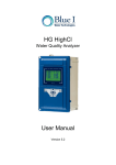
Innovative Control Solutions For Your Needs
R851V STEP CONTROLLER
WITH INTEGRATED VERNIER STAGE
•
•
•
•
Pulsed or analog 0 to 10 Vdc vernier stage
4 or 8 step models
Up to 16 stage total with a slave unit
Test button
SPECIFICATIONS
DESCRIPTION
The Viconics R851V series step controller is designed for
cost effective, precise modulation of multi-stage control
application. A common application is a multi step electric
duct heater.
An integrated vernier control output will give a precise and
full modulation of the load from 0 to 100% of the total
capacity.
FEATURES AND BENEFITS
Microcomputer-based design Accuracy and reliability
Adjustable inter-stage delay
Provides flexibility in
replacement applications
Adjustable Vernier ratio
Simplifies design of
proportional stage
Choice of pulsed or analog
Permits use of SCR or lower
Vernier output
cost SSR
Up to 16 stages
One product family can handle
all applications
Choice of LIFO or FIFO
Increased flexibility of FIFO
sequencing
permits even use of contactors
Test button
Quick troubleshooting
Operating
Conditions:
0°C to 80°C ( 32°F to 176°F )
0 % to 95 % R.H. non-condensing
Relay outputs:
Pilot duty:
24 - 120 Vac – 720 VA
240 Vac
– 690 VA
Motor load:
120 Vac – 1 HP
240 Vac – 2 HP
Vernier stage:
0 to 10 Vdc 5 mA max.
Vdc pulsed, 6 Vdc, 30 mA max.
Input
impedance:
0 to 10 Vdc into 10 KΩ minimum
Power supply:
24 Vac -15%, +10% 50/60 Hz; up to18 VA
Use a Class 1 ( properly fused ) or Class 2,
CSA or UL recognized transformer for power
supply & relay outputs.
UL recognized:
MODELS AVAILABLE
The R851-V is available in 2 models
•
R851V-4
4 stage unit
•
R851V-8
8 stage unit
If more than 8 stages are required, the R851-V8 can be used as
a master unit with another R851V as a slave unit. Adding
another unit ( R851V-4 or R851V-8 ) can bring the total step
number up to 12 or 16.
File # E212649
Specifications and equipment are subject to change without prior notice.
OVERRIDE TEST BUTTON
The override test button can be used to by-pass the interstage
delay and bring on all stage at one time. This simplifies the
verification of configured maximum number of stages. A status
led per step will come on for each of the configured stage.
INPUT SIGNAL
The R851V has four INPUT dip switch (S1 to S4) to select the control signal input:
They are compatible with industry standard signals.
DIP SWITCH ADJUSTMENTS & WIRING CONTROL INPUT
(1-4) Input
signal selection
0 to 10 Vdc
ON
1 2
3
4
ON
4 to 20 mA
1 2
3
4
ON
0 to 135 Ω
1 2
3
4
5 6
(3-6) Number of steps selection
(see next pages for details)
(2) Vernier stage selection
OFF = 0 to 10 Vdc (SCR)
ON = Vdc pulsed signal (SSR)
(1) Sequence of operation
(LIFO or FIFO)
OFF = LIFO (Last IN, First OUT)
ON = FIFO (First IN, First OUT)
1 2
3
SW1
4
4
(1-4) Input
signal selection
0 to 10 Vdc
ON
1 2 3
4
ON
4 to 20 mA
1 2 3
4
ON
0 to 135
Ω
1 2 3
Input Signal Switch
Switch #1
0 to 10 Vdc control signal ( 2 to 10 Vdc control range )
Off
4 to 20 mA control signal
Off
On
0 to 135 Ω control signal
If a slave unit is used, wire the control signal input to the master unit only
4
1 2
3
4
C
O
N
T
R
O
L
3
ON
I
N
P
U
T
1 2
ON
SW 2
SW1
4
C
O
N
T
R
O
L
3
I
N
P
U
T
1 2
R851V-4
ON
SW 2
R851V-8
ON
(3-4) Number of steps selection
(see next pages for details)
(2) Vernier stage selection
OFF = 0 to 10 Vdc (SCR)
ON = Vdc pulsed signal (SSR)
(1) Sequence of operation
(LIFO or FIFO)
OFF = LIFO (Last IN, First OUT)
ON = FIFO (First IN, First OUT)
Switch #2
Off
Off
On
Switch #3
Off
On
Off
Switch #4
On
Off
Off
1
0 To 135Ω Stand Alone Thermostat
1
1
2 To 10 Vdc Or 0 To 10 Vdc Stand Alone Thermostat
( Power To The Thermostat Is Supplied By The R851V )
ON
ON
4
2
3
4
I
N
P
U
T
3
1
2
3
2
I
N
P
U
T
1
2
3
1
1
0 Ohms = 0% capacity
135 Ohms = 100% capacity
2 Vdc = 0% capacity
10 Vdc = 100% capacity
Common
W
24 Vac
R
0 to 10 Vdc
output
B
4 To 20 mA From D.D.C.
Building Automation System
1
1
2 To 10 Vdc Or 0 To 10 Vdc From D.D.C.
Building Automation System
ON
ON
4
1
2
3
4
I
N
P
U
T
3
1
2
3
2
I
N
P
U
T
1
2
3
1
4 mA = 0% capacity
20 mA = 100% capacity
2 Vdc = 0% capacity
10 Vdc = 100% capacity
+
+
24 VAC POWER & RELAY OUTPUT WIRING
The wiring diagrams are for the R851V-8 models with 8 outputs. The wiring for the R851V-4 is the same except that the unit only
has 4 outputs.
Terminals
Screw terminal & connector #1
Screw terminal & connector #2
Screw terminal & connector #3
•
•
•
Common
24 Vac
Control Signal input
It is not necessary to ground any leg of the transformer to earth with the controller card.
The controller uses internally a half wave rectifier bridge. On 0 to 10 Vdc control signal, the reference of the control signal is the
Common of the power supply of the SCR controller card.
Use a Class 1 ( properly fused ) or Class 2, CSA or UL recognized transformer.
4 STAGE APPLICATION
R851V-4
R851V-4 Control Switch
Switch #3
Switch #4
Off
Off
On
Off
Off
On
On
On
ON
ON
2
3
4
1
2
3
4
200
I
N
P
U
T
C
O
N
T
R
O
L
1
1
2
3
Number of
stage
1
2
3
4
2
8 STAGE APPLICATION
R851V-8
ON
ON
R851V-8 Control Switch
Switch #4
Switch #5
Off
Off
Off
Off
On
Off
On
Off
Off
On
Off
On
On
On
On
On
12 STAGE APPLICATION
2
3
3
4
1
4
5
6
( See also slave application section at the end )
ON
2
ON
ON
2
3
4
5
6
1
2
3
4
1
2
3
4
20 0
I
N
P
U
T
C
O
N
T
R
O
L
1
2
3
1
1
Switch #6
Off
Off
Off
Off
Off
Off
Off
Off
R851V-8 MASTER UNIT, R851V-4 SLAVE UNIT
ON
4
I
N
P
U
T
C
O
N
T
R
O
L
•
Switch #3
Off
On
Off
On
Off
On
Off
On
3
1
2
3
Number of
stage
1
2
3
4
5
6
7
8
2
I
N
P
U
T
C
O
N
T
R
O
L
1
2
3
1
Note: Set all control signal INPUT dip switch to OFF on
slave unit.
Number
R851V-8 Master Unit Control Switch
R851V-4 Slave Unit
of stage
Switch #3
Switch #4
Switch #5
Switch #6
Switch #3
Switch #4
9
Off
Off
Off
On
Off
Off
10
On
Off
Off
On
On
Off
11
Off
On
Off
On
Off
On
12
On
On
Off
On
On
On
The intensity of the yellow status LED on the master unit is proportional to the slave output.
3
R851V-8 MASTER UNIT, R851V-4 SLAVE UNIT
ON
ON
ON
2
3
4
1
2
3
4
5
1
6
I
N
P
U
T
C
O
N
T
R
O
L
1
2
3
1
( See also slave application section at the end )
ON
2
3
4
1
2
3
4
5
6
I
N
P
U
T
C
O
N
T
R
O
L
16 STAGE APPLICATION
1
2
3
•
Note: Set all control signal INPUT dip switch to OFF
on slave unit.
Number
R851V-8 Master Unit Control Switch
R851V-8 Slave Unit Control Switch
of stage
Switch #3
Switch #4
Switch #5
Switch #6
Switch #3
Switch #4
Switch #5
Switch #6
9
Off
Off
Off
On
Off
Off
Off
Off
10
On
Off
Off
On
On
Off
Off
Off
11
Off
On
Off
On
Off
On
Off
Off
12
On
On
Off
On
On
On
Off
Off
13
Off
Off
On
On
Off
Off
On
Off
14
On
Off
On
On
On
Off
On
Off
15
Off
On
On
On
Off
On
On
Off
16
On
On
On
On
On
On
On
Off
The intensity of the yellow status LED on the master unit is proportional to the slave output.
R851V DIMENSIONS & INSTALLATION
ON
ON
2
3
4
1
2
3
4
5
6
I
N
P
U
T
C
O
N
T
R
O
L
1
2
3
1
Install on the mounting plate on the electrical cabinet using five #6 pan head metal screw. Do not over torque the screws to prevent
damage to the board. Specifications and equipment are subject to change without prior notice.
All R851V series controls are for use only as operating controls. Whenever a control failure could lead to personal
injury and/or loss of property, it becomes the responsibility of the user to add safety devices and/or alarm system
to protect against such catastrophic failures.
4
LIFO / FIFO ADJUSTMENT
The R851V series features 2 different staging sequences:
•
LIFO
LAST IN FIRST OUT ( CONTROL SWITCH #1 OFF, FACTORY DEFAULT )
This is the regular mode. Stage #1 will always be the first to energize and the last stage to de-energize
•
FIFO
FIRST IN FIRST OUT ( CONTROL SWITCH #1 ON )
In this mode, the stages are rotated to ensure a more uniform wear of the contactors and elements. For example, on an increase in
demand, stage 1 will be energized following by stage 2, etc. On a decrease in demand, stage 1 will de-energized first followed by
stage 2, etc.
Please verify that if this mode is enabled, the manufactured product still complies with active codes and regulations.
VERNIER STAGE SELECTION AND WIRING
The Viconics R851V series step controller has an integrated vernier control output. This output will give a precise and full
modulation of the load from 0 to 100% of the total capacity of the unit. If a master slave application is used, always connect the
vernier output of the master unit.
ADJUSTMENTS
Functions of the units can be configured with six dip switch and 2 potentiometers.
Interstage delay potentiometer setting
Two potentiometers are used to adjust the interstage delay from 5 seconds up to10 minutes.
0 to 9 min.
5 to 60 sec.
150
125
100
175
200
This delay is active in 3 ways.
• Minimum time delay between each step activation when the control signal rises
• Minimum ON time when the step is activated
• Minimum time delay between each step de-activation when the control signal drops
Vernier stage ratio
A potentiometer is used to adjust the vernier stage ratio from 100% to 200% capacity of the other on/off
stage capacity.
RATIO SETTING
( See also slave application section at the end )
First adjust the vernier stage ratio potentiometer. This will insure a smooth capacity rise of the total load.
150
Example 1:
VR2
200
100
The total unit has 100 kW divided in 10 equal stage of 10 kW.
RATIO(%)
If only 10 kW is used as the modulating stage, then the heater would have 9 on/off mechanical stage plus
one modulating stage. This modulating stage has the same value as all the other stage. Adjust the vernier stage ratio
potentiometer to 100%.
Example 2:
The total unit still has 100 kW divided in 10 equal stage of 10 kW.
If 20 kW are used as the modulating stage, then the heater would have 8 on/off mechanical stage plus one modulating stage.
The modulating stage has twice the value as all the other stage. Adjust the vernier stage ratio potentiometer to 200%.
•
TYPE OF VERNIER STAGE SETTING
The vernier stage output can be configured to operate either as a:
•
•
Vdc pulsed output to activate an R810 power module
0 to 10 Vdc analog output to activate an R820 SCR power controller.
5
•
VERNIER STAGE WIRING
Control Switch #2 On
Vdc pulsed to activate R810 power modules
Do not wire more than six R810 power module on the
vernier stage output
Respect the polarity between the R851 step controller
board an the R810 power modules
COM
V
S
R810
Connect
Connect
-
+
V to +
COM to -
The green status LED on the master unit will cycle at
the same rate as the time proportioning vernier output
For more information, please refer to the R810 service
manual
0 to 10 Vdc analog output to activate R820 SCR power controller
Control Switch #2 Off
Set the R820 SCR power controller to accept a 0 to 10 Vdc control signal input
Switch #1, #2 & #3 Off
Switch #4 On
The intensity of the green status LED on the master unit is proportional to vernier output
For more information, please refer to the R820 service manual
R820
SCR Power Controller
ON
1 2 3
1
ON
2
3
4
1
2
3
4
5
6
I N PU T CON T R OL
1 2 3
SLAVE APPLICATION SECTION
When using a unit for slave applications, it is important that the proper adjustments & setting be made to the unit for proper
operation of the system.
The yellow LED near the vernier output connector is proportional to the vernier output of the master unit ( 0 to 5 Vdc ).
On the slave unit:
Set vernier ratio potentiometer to 100%
Set interstage delay potentiometer to the same value as the master unit
Set all control signal INPUT dip switch to OFF
ON
2
3
4
I
N
P
U
T
1
1
2
3
•
•
•
TEST MODE BUTTON
The test mode button can be used to verify if the number of stage have been configured properly.
1.
2.
3.
4.
5.
Press and hold the button for 3 to 4 seconds.
If a slave unit is used, press & hold the 2 units button simultaneously
All the selected stage will come on, one after the other until all selected number of stages are all on.
There is a delay of approximately 5 second between each step activation.
When all selected stage are on, they will stay on for approximately 30 seconds before shutting down.
Powering up the R851V controller while holding down the test button will by-pass the interstage delay for 10 minutes. During that
period, the unit will respond to a changing signal input very rapidly. Also hold down slave test button on start-up if a slave unit is
used. After that 10 minute period, the unit will function normally with the interstage delays active
Viconics Electronics Inc.
9245, Langelier Blvd, St-Leonard, Quebec, Canada H1P 3K9
www.viconics.com
[email protected]
LIT-R851V-E03
028-5009 – REV.2
6