1
HITACHI PROGRAMMABLE CONTROLLER
Compact remote2 module
Master: EH-TRME2
Slave: EH-TRLE2
APPLICATION MANUAL
(SERVICE MANUAL)
NJI-585 (X)
{ Warranty period and coverage
The warranty period is the shorter period either 18 months from the date of manufacture or 12
months from the date of installation.
However within the warranty period, the warranty will be void if the fault is due to;
(1) Incorrect use as directed in this manual and the application manual.
(2) Malfunction or failure of external other devices than this unit.
(3) Attempted repair by unauthorized personnel.
(4) Natural disasters.
The warranty is for the PLC only, any damage caused to third party equipment by malfunction of
the PLC is not covered by the warranty.
{ Repair
Any examination or repair after the warranty period is not covered. And within the warranty period
any repair and examination which results in information showing the fault was caused by any of the
items mentioned above, the repair and examination cost are not covered. If you have any questions
regarding the warranty please contact either your supplier or the local Hitachi Distributor.
(Depending on failure part, examination might be impossible.)
{ Ordering parts or asking questions
When contacting us for repair, ordering parts or inquiring about other items, please have the
following details ready before contacting the place of purchase.
(1) Model
(2) Manufacturing number (MFG NO.)
(3) Details of the malfunction
Warning
(1) Reproduction of the contents of this manual, in whole or in part, without written permission of Hitachi-IES,
is prohibited.
(2) The content of this document may be changed without notice.
(3) While efforts have been made to be accurate, if any wrong or missing information is found, please contact
us.
MS-DOS®, Windows®, and Windows NT® are registered trademarks of America and other registered countries
of Microsoft Corp. of the United States.
Safety Precautions
Read this manual and related documents thoroughly before installing, operating, performing preventive maintenance or
performing inspection, and be sure to use the unit correctly. Use this product after acquiring adequate knowledge of
the unit, all safety information, and all cautionary information. Also, make sure this manual enters the possession of the
chief person in charge of safety maintenance.
Safety caution items are classified as “Danger” and “Caution” in this document.
DANGER
: Identifies information about practice or circumstances, which may lead to personal injury
or death, property damage, or economic loss.
CAUTION
: Identifies information about practice or circumstances, which may lead to personal injury,
property damage, or economic loss.
However, depending on the circumstances, items marked with
CAUTION
may result in major accidents.
The both marks show important information. Be sure to follow the instructions.
Icons for prohibited items and required items are shown below:
: Identifies prohibition. For example, when open flames are prohibited,
: Identifies requirement. For example, when grounding must be performed,
is indicated.
is indicated.
1. Installation
CAUTION
Use this product in an environment as described in the catalog and this document.
If this product is used in an environment subject to high temperature, high humidity, excessive dust, corrosive
gases, vibration or shock, it may result in electric shock, fire or malfunction.
Be sure to install the PLC according to this manual. Failure to do so could result in damage by falling off,
failure or malfunction.
Do not allow foreign objects such as wire chips to enter the unit.
They may become the cause of fire, malfunction or failure.
2. Wiring
REQUIRED
The PLC must be grounded (FE terminal).
Failure to do so could result in injury to personnel or causing it to malfunction.
CAUTION
Always use the power supply voltage listed in specifications. Using other voltage may damage the equipment
or present a risk of fire.
The wiring operation should be performed by a qualified personnel.
Failure to do so could result in fire, damage or electric shock.
3. Precautions when using the unit
DANGER
Do not touch the terminals while the power is on.
There is risk of electric shock.
Appropriate emergency stop circuit, interlock circuitry and similar safety measures should be added to the PLC
system to ensure safety in the event of incorrect, missing or abnormal signals caused by broken signal lines,
momentary power interruptions or other causes. Do not share the power supply of relay output module and
interlock circuitry because relay output might not work properly due to switching noise from interlock
circuitry.
CAUTION
When performing program change, forced output, RUN, STOP, etc., while the unit is running, be sure to check
system safety carefully. Failure to do so could lead to damage to equipment.
Supply power according to the power-up order.
Failure to do so could lead to damage to equipment or malfunction.
CAUTION
USE POWER SUPPLY UNIT OF EH-PS SERIES FOR SUPPLYING ELECTRIC POWER.
CAUTION
DO NOT CONNECT EH-PSD DIRECTLY TO LINE VOLTAGE. LINE VOLTAGE MUST BE SUPPLIED
BY A SUITABLE, APPROVED ISOLATING TRANSFORMER HAVING SHORT CIRCUIT CAPACITY
NOT EXCEEDING 150 VA MAXIMUM.
4. Preventive maintenance
DANGER
Do not connect the “+/-“ of the battery in reverse polarity. Do not recharge, disassemble, heat, place in fire,
or short circuit the battery. There is a risk of explosion or fire.
PROHIBITED
Do not attempt to disassemble, repair or modify any part of the PLC.
Electric shock, malfunction or failure may result.
CAUTION
Turn off power to the PLC before mounting or dismounting the module.
Electric shock, malfunction or failure may result.
MEMO
Revision History
No.
1
Description of Revision
First edition
Date of Revision
Manual Number
Mar. 2013
NJI-585 (X)
Table of contents
Chapter 1
Introduction
1.1
1-1 to 1-10
Use combination of products ..................................................................................................................... 1 1.1.1 Available CPU module and programming software ......................................................................... 1 1.1.2 Combination of CPU modules and base units................................................................................... 1 1.2 Before use.................................................................................................................................................. 11.3 Features ..................................................................................................................................................... 1-
Chapter 2
Specifications
1
1
5
6
7
2-1 to 2-12
2.1
2.2
2.3
General specifications................................................................................................................................ 2- 1
Functional specifications ........................................................................................................................... 2 - 2
Units that can be connected to compact remote2 module.......................................................................... 2 - 3
2.3.1 Remote slaves that can be connected to remote master (EH-TRME2) ............................................. 2 - 3
2.3.2 Remote masters that can be connected to remote slave (EH-TRLE2) .............................................. 2 - 4
2.3.3 Occupied channels of the conventional product ............................................................................... 2 - 5
2.4 Difference with the compact remote module ............................................................................................ 2 - 9
2.4.1 Specifications comparison of master module.................................................................................... 2 - 9
2.4.2 Specifications comparison of slave module ...................................................................................... 2 - 10
2.5 List of mountable modules of slave module (EH-TRLE2) ........................................................................ 2 - 11
Chapter 3
Name and function of each part
3.1
3.2
Chapter 4
Name and function of each part in master module ................................................................................... 3 - 1
Name and function of each part in slave module....................................................................................... 3 - 6
Basic functions and System configuration
4.1
4.2
3-1 to 3-10
4-1 to 4-46
Method of using compact remote2 and selection of CPU ......................................................................... 4 - 1
Basic functions of compact remote2.......................................................................................................... 4 - 3
4.2.1 Channels and remote I/O area........................................................................................................... 4 - 3
4.2.2 Master number and slave station number.......................................................................................... 4 - 3
4.2.3 Occupied channels and method of appointing .................................................................................. 4 - 4
4.2.4 Correspondance of occupied channels and I/O slots (Normal remote method) ............................... 4 - 5
4.2.5 Compression mode of master module (Compression remote method) ............................................. 4 - 6
4.2.6 External I/O method (X4Y4W) (Compression mode of slave module) ........................................... 4 - 8
4.2.7 External I/O method (Y8W, X8W) .................................................................................................. 4 - 9
4.2.8 Occupied channels of EH-TRLE2 .................................................................................................... 4 - 11
4.3 Basic system configuration........................................................................................................................ 4 - 12
4.3.1 Basic system configuration (REMOTE(RMM) method) ................................................................. 4 - 12
4.3.2 Basic system configuration (Normal remote method) ...................................................................... 4 - 14
4.3.3 Basic system configuration (Y8W method) ..................................................................................... 4 - 16
4.3.4 Basic system configuration (X4Y4W method) ................................................................................ 4 - 18
4.3.5 Basic system configuration (X8W method) ..................................................................................... 4 - 20
4.4 Replacement from H-200/250/252B/252C ................................................................................................ 4 - 22
4.4.1 Replacement with normal remote method ........................................................................................ 4 - 22
4.4.2 Replacement with compression remote method ............................................................................... 4 - 24
4.5 Replacement from Remote I/O MINI of Large H series............................................................................ 4 - 26
4.5.1 Replacement from Remote I/O MINI with mode1............................................................................ 4 - 26
4.5.2 Replacement from Remote I/O MINI with mode2............................................................................ 4 - 28
4.5.3 Replacement from Remote I/O MINI with mode3............................................................................ 4 - 30
4.5.4 Replacement from Remote I/O MINI with mode0............................................................................ 4 - 32
4.6
Replacement from EM/EM-II series.......................................................................................................... 4 - 35
4.6.1 Replacement with normal remote method ........................................................................................ 4 - 35
4.6.2 Replacement with compression remote method................................................................................ 4 - 37
4.7 Replacement of slave station only ............................................................................................................. 4 - 39
4.7.1 Basic method for replacement of slave station only ......................................................................... 4 - 39
4.7.2 Replacement of slave station only for Remote I/O MINI with mode0.............................................. 4 - 41
4.8 Response time............................................................................................................................................ 4 - 43
Chapter 5
Installation and Turning power supply on
5.1
5.2
5.3
5.4
5.5
Chapter 6
Chapter 7
1
2
4
4
5
8
7-1 to 7-2
Daily inspection......................................................................................................................................... 7 - 1
Periodic inspection .................................................................................................................................... 7 - 1
Appendix
8.1
1
2
3
4
7
6-1 to 6-10
Error indication.......................................................................................................................................... 6 Special internal outputs in CPU module.................................................................................................... 6 Operation parameters related to remote system......................................................................................... 6 Function of reset switch............................................................................................................................. 6 Error detection and running of CPU .......................................................................................................... 6 Troubleshooting ........................................................................................................................................ 6 -
Daily and Periodic Inspection
7.1
7.2
Chapter 8
Loading the module ................................................................................................................................... 5 Mountable slots for remote module ........................................................................................................... 5 How to prepare of twisted pair cables ....................................................................................................... 5 Connection of twisted pair cables.............................................................................................................. 5 The order of turning on power supply ....................................................................................................... 5 -
Error indication and Countermeasure
6.1
6.2
6.3
6.4
6.5
6.6
5-1 to 5-8
8-1 to 8-3
Choice guideline of the twisted pair cable................................................................................................. 8 8.1.1 Electrical characteristic..................................................................................................................... 8 8.1.2 Cable structure .................................................................................................................................. 8 8.1.3 Cable length ...................................................................................................................................... 8 8.1.4 Terminator ........................................................................................................................................ 8 -
1
1
2
2
3
MEMO
Chapter 1
Introduction
Thank you very much for choosing Hitachi Programmable Controller (hereinafter referred to as PLC) EH-150 series.
This manual explains how to use the compact remote2 module with the Hitachi EH-150 Programmable Controller. Read
this manual thoroughly and keep for installation operations, maintenance checks and other procedures. The following
documentation related to PLC is also available and should be used together with this manual.
Table 1.1.1 List of Description materials
Items
EH-150
(EHV) series
EH-150 series
Title of document
Manual number
Main system of EH-150
EH-150 EHV-CPU APPLICATION MANUAL
NJI-481*(X)
Programming software
(Standard Edition)
Programming software
(Variable Name Edition)
Main system of EH-150
Programming software
EH-150 EHV-CPU PROGRAMMING MANUAL
EH-150 EHV series Ladder Programming software
Control Editor INSTRUCTION MANUAL
EH-150 EHV series Ladder Programming software
Control Editor INSTRUCTION MANUAL
EH-150 APPLICATION MANUAL
H-SERIES
LADDER EDITOR for Windows®
INSTRUCTION MANUAL
NJI-482*(X)
NJI-537*(X)
NJI-486*(X)
NJI-281* (X)
NJI-342* (X)
* The alphabet between the number and (X) means version (A, B…) and the space means the first edition.
1.1
Use combination of products
1.1.1 Available CPU module and programming software
EH-TRME2/EH-TRLE2 is usable in combination with the products of the model as shown in Table 1.1.2.
Table 1.1.2 Usable CPU modules and supported versions of programming software
CPU modules
Model name
EHV-CPU128
EHV-CPU64
EHV-CPU32
Supported version
“REMOTE2”:
"ROM VER.*110" or later
“REMOTE (RMM)”:
"ROM VER.*117" or later
EHV-CPU16
Programming software
Product name
Model name
Supported version
Standard
Edition
EH-CTE-E
Ver.2.18 or newer
Variable Name
Edition
EH-CTE-EVN
Ver.2.22 or newer
HLW-PC3E
Not depend on the
software version of
programming software.
Control
Editor
EH-CPU548
EH-CPU516
EH-CPU316A
Not depend on the software
version of CPU.
LADDER EDITOR
for Windows®
EH-CPU208A
EH-CPU104A
1–1
Chapter 1
Introduction
I/O assignment by Control Editor and Ladder Editor
When setting I/O assignment of modules by programming software, notation of I/O information to choose at I/O
assignment is different from Control Editor and Ladder Editor.
With the following manuals, the I/O information is mentioned the notation of Control Editor as shown in Table 1.1.3.
Table 1.1.3 I/O information notation by the programming software
I/O information that choose in
I/O assignment setting
REMOTE (RMM)
Programming software
Ladder Editor
Control Editor
Non-support
“EH-TRMM (2048)”, “REMOTE (RMM)”
REMOTE2
“Remote2”
“EH-TRMME (REMOTE2)”, ”REMOTE2”
Input 4 words / Output 4 words
“Word 4W/4W”
“EH-TRMME (X4Y4W)”, ”X4Y4W”
Input 8 words
“Word X8W”
“X8W”
Output 8 words
“Word Y8W”
“Y8W”
I/O assignment for remote master with control editor
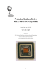
In the Control Editor, you can set I/O assignment by selecting model name with I/O assignment screen like Figure
1.1.1. In the case of setting “REMOTE (RMM)”, select EH-TRMM (2048) from “Others” tag as shown in Figure
1.1.1.
1
2
3
In “Others” tag
Select “EH-TRMM (2048)”
“REMOTE (RMM)” is assigned.
Figure1.1.1 I/O assignment for remote master with control editor (in the case of “REMOTE (RMM)”)
1–2
Chapter 1
Introduction
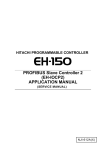
In the case of setting “REMOTE2”, select EH-TRMME (REMOTE2) from “Others” tag as shown in Figure 1.1.2.
And in the case of setting I/O assignment “X4Y4W”, select EH-TRMME (X4Y4W) from “Others” tag as shown in
Figure 1.1.3.
1
2
3
In “Others” tag
Select “EH-TRMME (REMOTE2)”
“REMOTE2” is assigned.
Figure1.1.2 I/O assignment for remote master with control (in the case of “REMOTE2”)
1
2
3
In “Others” tag
Select “EH-TRMME (X4Y4W)”
“X4Y4W” is assigned.
Figure1.1.3 I/O assignment for remote master with control editor (in the case of “X4Y4W”)
1–3
Chapter 1
Introduction
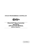
In the case of setting I/O assignment “Y8W” or “X8W”, select from “I/O Config” tag as shown in Figure 1.1.4 or
Figure 1.1.5.
1
2
3
In “I/O Config” tag
Select “Y8W”
“Y8W” is assigned.
Figure1.1.4 I/O assignment for remote master with control editor (in the case of “Y8W”)
1
2
3
In “I/O Config” tag
Select “X8W”
“X8W” is assigned.
Figure1.1.5 I/O assignment for remote master with control editor (in the case of “X8W”)
1–4
Chapter 1
Introduction
1.1.2 Combination of CPU modules and base units
Use EH-TRME2 with products shown in Table 1.1.4.
Table 1.1.4 Supported CPUs and base units
Limit of mounting for I/O assignment
CPU modules
EHV-CPU128
EHV-CPU64
EHV-CPU32
EHV-CPU16
EH-CPU548
EH-CPU516
Base units
“Y8W” ”X8W”
“REMOTE (RMM)”
“X4Y4W”
EH-BS3/ 5/ 8
EH-BS3A/ 5A/ 6A/ 8A/ 11A
EH-BS3/ 5/ 8
EH-BS3A/ 5A/ 6A/ 8A/ 11A
EH-BS3A/ 5A/ 6A/ 8A
Slot 0 to 7
No limitation
Slot 0 to 2
No limitation
Slot 0 to 7
No limitation
Not usable
No limitation
EH-BS11A
EH-CPU208A
EH-CPU104A
Remarks
Not usable. (Note 1)
EH-BS3/ 5/ 8
EH-CPU316A
“REMOTE2”
Refer to Table 1.1.5
Refer to Table 1.1.5
Refer to Table 1.1.5
Not usable. (Note 2)
EH-BS3/ 5/ 8
EH-BS3A/ 5A/ 6A/ 8A
Not usable
No limitation
EH-BS11A
Not usable. (Note 2)
(Note 1) EHV-CPU*** can be not used with EH-BS3/BS5/BS8.
(Note 2) EH-BS11A can be not used with EH-CPU104A/208A/316A.
See Table 1.1.5 about specifications of base unit. When using EH-TRME2 by I/O assignment of "REMOTE2"
“REMOTE (RMM)”, mount EH-TRME2 on module slots that can mount communication modules in the basic base.
Table 1.1.5 Specifications of base units
Base units
The number of
mounted modules
Available slot number
for communication
modules
EH-BS3
3 modules
EH-BS5
5 modules
EH-BS8
8 modules
EH-BS3A
3 modules
EH-BS5A
5 modules
Slot 0 to 4
EH-BS6A
6 modules
Slot 0 to 5
EH-BS8A
8 modules
EH-BS11A
11 modules
Remarks
Discontinued
Slot 0 to 2
Discontinued
Discontinued
Slot 0 to 7
1–5
Chapter 1
1.2
Introduction
Before use
Great care has been taken in the manufacture of this product, but we advise that the following points are checked
immediately after purchase.
1. Is the model the same one that you ordered?
2. Has the product been damaged in any way?
3. Are any of the accessories listed in Table 1.2.1 and Table1.2.2 missing?
Contact your dealer in the event of any defects being discovered.
Table 1.2.1 List of accessories supplied with the EH-TRME2
No.
1
Product name
Compact remote2
Model name
Appearance
Quantity
EH-TRME2
1
BL3.5/6F
1
Remarks
master module
2
Connector
Plugged in the connector for
communication.
Made by Weidmuller
3
Instruction manual
NJI-583* (X)
1
(Note1)
(Note1) The alphabet between the number and (X) means version (A, B…) and the space means the first edition.
Table 1.2.2 List of accessories supplied with the EH-TRLE2
No.
1
Product name
Compact remote2
Model name
Appearance
Quantity
EH-TRLE2
1
BL3.5/6F
1
Remarks
slave module
2
Connector
Plugged in the connector for
communication.
Made by Weidmuller
3
External terminator
1
100Ω
Connect it when you use
fallback operation. (Note2)
4
Instruction manual
NJI-584* (X)
1
(Note1)
(Note1) The alphabet between the number and (X) means version (A, B…) and the space means the first edition.
(Note2) Please refer to Section 6.5 for fallback operation, and refer to Section 5.4 for connection.
1–6
Chapter 1
1.3
Introduction
Features
(1) Maximum remote I/O: 2,048 points
Maximum remote I/O expands to 2,048 points, which enables to structure large-scale control system.
(2) 32-point, 64-point I/O module, and analog I/O modules attachable in each slave station
32-point, 64-point I/O module, and analog I/O modules are attachable to each compact remote 2 slave module, and can
control up to 704 points (by using 64-point I/O module) or 88 channels (by using analog module) maximum.
(3) Available to read out I/O assignment information of slave station
Programming of I/O assignment setting becomes easier, since compact remote 2 module can read out I/O assignment
information of each slave station in normal mode.
(4) Compatibility with compact remote module
Compact remote 2 modules are functions are compatible with our current compact remote module (EH-TRMME,
EH-TRMLE). Kindly recommend each customer to use compact remote 2 modules whenever they install new system.
(5) Available for partial replacement
Since both master and slave modules are available to use with our current models, customer can easily replace to
EH150/EHV series by partially replacing its modules without any change of I/O wiring.
(6) Quick response and high reliability
Remote refresh time is approximate 46ms (High-speed mode setting, based on condition of 2,048 I/O points), and also
achieve high reliability based on its reverse double-transmission check function, which discard improper
communication data.
(7) I/O hold function
Since a slave module has an output hold function and a master module has an input hold function from the remote
slave module, these modules are applicable to the process control.
(8) Easy handling
The cable for these modules is easily-available due to the twist cable and easy to handle.
1–7
Chapter 1
Introduction
The configuration example of the remote I/O system is shown below.
(1) Large-scale remote I/O system (EHV-CPU16/32/64/128, EH-CPU316A/516/548)
You can build the large-scale remote I/O system of maximum 2,048 points / systems in EHV/EH-150 series by
the compact remote2 module which a cheap twisted pair cable can use at low cost.
Remote master
(EH-TRME2)
Max. 4 systems
I/O LINK
(EH-TRLLE)
I/O LINK
(EH-TRLLE)
Remote slave
(EH-TRLE2)
・・・
EHV
No.1 Remote
Remote slave
(EH-TRLE2)
Remote slave
(EH-TRLE2)
Remote slave
(EH-TRLE2)
・・・
No.2 Remote
No.3 Remote
Large-scale remote I/O system
Module counts: max. 12 slave units / system
Remote I/O points: max. 2,048 points / system
Remote slave
(EH-TRLE2)
Remote slave
(EH-TRLE2)
Remote slave
(EH-TRLE2)
・・・
No.4 Remote
Note) Set “REMOTE (RMM)” to master module in the remote I/O system of maximum 2,048 points / system.
Therefore, use EHV-CPU in large-scale remote I/O system
Figure 1.3.1 System configuration example of compact remote module
(2) Low cost remote I/O system (EH-CPU104A/208A/316A)
The CPU (EH-CPU104A/208A/316A) for small-scale control was not able to use a remote module, but
compact remote module can build an remote I/O system by the CPU.
Remote master
(EH-TRME2)
Remote slave
(EH-TRLE2)
Remote slave
(EH-TRLE2)
Remote slave
(EH-TRLE2)
・・・
EH-CPU
Low-cost remote I/O system
Compact remote module can build
remote I/O system of 128 points by
setting I/O assignment “Y8W”,
“X4Y4W” or “X8W”.
No mountable restrictions
Because the I/O assignment is not "remote
assignment", there are not the mountable restrictions.
Figure 1.3.2 System configuration example 1 of EH-CPU104A/208A/316A
1–8
Chapter 1
Introduction
(3) Small-scale remote I/O system (EH-CPU104A/208A/316A)
EH-CPU104A/ 208A/ 316A can build I/O link system of 128 points / systems by setting I/O assignment of
master module in "X4Y4W". In addition, you can build the remote I/O system by adding master module.
Because the I/O assignment is not "remote
assignment", there are not the mountable restrictions.
EH-CPU104A
I/O LINK
(EH-TRLLE)
Remote slave
(EH-TRLE2)
Remote slave
(EH-TRMLE)
Small-scale I/O system
Module counts: 1 slave unit (EH-TRLLE)
Link points: 128 points
Small-scale remote I/O system
Module counts: max. 8 slave units
Remote I/O points: 128 points
Figure 1.3.3 System configuration example 2 of EH-CPU104A/208A/316A
(4) Remote I/O system with the existing PLC
Since EH-TRME2/TRLE2 has communication-compatibility with current models “REM-MMH/LMH/LH2”,
“RIOH-TM/TL” or “RIOM-TM/TL”, it is possible to replace existing PLC by EH-150/EHV series. Therefore you
can use compact remote modules with remote I/O system of the existing PLC.
Remote slave
(EH-TRLE2)
Remote master
(RIOH-TM)
EH-150/EHV
Remote slave
(EH-TRMLE)
Remote slave
(RIOH-TL)
EH-150/EHV
H-200/250/252B/252C
H-200/250/252B/252C
Figure 1.3.4 Replacement configuration example 1 of existing PLC
Remote master
(REM-MMH)
Remote slave
(REM-LMH)
Remote slave
(RIOH-TL)
Remote slave
(EH-TRLE2)
EH-150/EHV
H-200/250/252B/252C
H series
H series
Figure 1.3.5 Replacement configuration example 2 of existing PLC
Refer to Chapter 2 or later for the details of the usage.
1–9
Chapter 1
Introduction
MEMO
1 – 10
Chapter 2
2.1
Specifications
General specifications
General specifications are shown in Table 2.1.1. These specifications are common in EH-150 series.
Table 2.1.1 General specifications
Item
Specifications
Operating ambient temperature
0 to 55 °C
Storage ambient temperature
-10 to 75 °C
Operating ambient humidity
5 to 95 % RH (no condensation)
Storage ambient humidity
5 to 95 % RH (no condensation)
Vibration resistance
Noise resistance
Conforms to IEC 60068-2-6
○
○
○
Insulation resistance
Dielectric withstand voltage
Grounding
Usage environment
Noise voltage 1,500 Vpp Noise pulse width 100 ns, 1μs
(Noise created by the noise simulator is applied across the power supply module’s
input terminals. This is determined by this company’s measuring method.)
Based on IEC61131-2
Static noise: 3,000 V at metal exposed area
20 MΩ or more between the AC external terminal and case ground (FE) terminal
(based on 500 V DC)
1,500 V AC for 1 minute between the AC external terminal and case ground (FE) terminal
Class D grounding (ground with power supply module)
No corrosive gases, no excessive dust
Structure
Open, wall-mount type
Cooling
Natural air cooling
2–1
Chapter 2
2.2
Specifications
Functional specifications
Functional specifications are shown in Table 2.2.1. The compact remote2 modules have the functions to almost equal
with current remote modules as shown in section 2.3.
The compact remote2 modules have communication-compatibility with current remote I/O, and you can use an
existing cable. And you can do replacement from existing PLC.
Table 2.2.1 Functional specifications
Item
Specifications
Usable CPU
Number of mountable master
modules
Functional specifications
Number of connectable slave
modules
Number of I/O points
EH-CPU104A/208A/316A/516/548, EHV-CPU16/32/64/128
Remote master module: MAX. 4 units / CPU
(I/O assignment: “REMOTE2”, “REMOTE (RMM)”)
MAX. 4 units/1 master (I/O assignment: “X4Y4W”)
MAX. 8 units/1 master (I/O assignment: “REMOTE2” “Y8W” “X8W”)
MAX. 12 units/1 master (I/O assignment: “REMOTE (RMM)”)
128 points/master module (I/O assignment: “Y8W” “X4Y4W” “X8W”)
1,024 points/master module (I/O assignment: “REMOTE2”)
2,048 points/master module (I/O assignment: “REMOTE (RMM)”)
46ms/2,048 points (HS: ON), 94ms/2,048 points (HS: OFF)
SRAM check, WDT check, Loop back check
Available (Even if a slave module is failed or powered off, it is possible to continue
communication between a master module and other slave modules)
Master module: ”REMOTE (RMM)” “REMOTE2” “Y8W” “X4Y4W” “X8W”
Slave module: No configuration code
8-point, 16-point, 32-point, 64-point I/O module or Dummy module
Mountable module on slave
(I/O assignment: “X16” “Y16” “X32” “Y32” “X64” “Y64” or “Empty 16”)
base (Note 3)
Analog I/O module (I/O assignment: “X4W” “X8W” “Y4W” “Y8W” etc.)
Consumption current
EH-TRME2: Approximately 200mA, EH-TRLE2: Approximately 200mA
Communication speed
768kbps
Transfer method
Half-duplex serial transfer, frame synchronization
Insulation, modulation method
Trans insulation, bipolar pulse modulation
Transmission error check
Reverse double-transmission, time-out
Error indication
LED, Special internal output
Connection mode
Multi-drop connection
2
2
2
Cable length
Between stations: 150m (0.3mm ) / 300m (0.5mm , 0.75mm )
2
2
2
(Note 4)
Total length: 150m (0.3mm ) / 300m (0.5mm , 0.75mm )
Error station processing
Slave station: Bypass system
Cable
Shielded twisted pair cable
0.3mm2 cable: CO-SPEV-SB (A)-1P-0.3SQ (Terminator 100Ω)
Recommended
Existing
cable
0.75mm2 cable: CO-EV-SX-1P-0.75SQ (Terminator 150Ω)
(Made by
0.3mm2 cable: CO-SPEV-SB (A)-1P-0.3SQ LF (Terminator 100Ω)
New
Hitachi cable)
0.5mm2 cable: CO-SPEV-SB (A)-1P-0.5SQ LF (Terminator 100Ω)
Applicable connector
BL3.5/6F attached (made by Weidmuller)
(Note 1) Please connect external terminator to the terminated compact remote 2 slave module instead of using built-in
terminator when you use fallback operation.
(Note 2) The I/O assignment of "REMOTE2" and "X4Y4W" is compatible operation mode to compact remote master module
(EH-TRMME). On the other hand, remote I/O was expanded to 1,024 points (64 words) in the I/O assignment of
"REMOTE2".
(Note 3) High-performance modules and communication modules, etc. cannot be mounted on the slave base.
(Note 4) Maximum-length of cable becomes as below.
Transmission line
Transmission
specifications
Refresh time
Self-diagnosis
Fallback operation
(Note 1)
I/O assignment
(Note 2)
No. of connected stations
2
0.3mm cable
2
2
0.5mm , 0.75mm cable
1 to 8 units
150m
300m
9 to 12 units
130m
260m
2–2
Chapter 2
2.3
Specifications
Units that can be connected to compact remote2 module
Compact remote2 modules have the compatible communication with "REM-MMH/LMH" for H series, the slave
station "REM-LH2" for H-200/250/252B/252C, or the slave station "HL-40DR/64DR and HR-40DR/64DR" for
H-board. Furthermore, compact remote2 modules are compatible with the compact remote modules for EH-150/EHV
in transmission specifications.
When EH-TRME2 is set to compatible mode, it can connect current slave module and EH-TRMLE for
EH-150/EHV series. In addition, when EH-TRLE2 is set to compatible mode, it can connect to EH-TRMME and
EH-TRLLE. When compact remote2 modules are connected with current model, please turn off high-speed refresh
mode (HS) of a front DIP switch of the module. In high-speed refresh mode (HS:ON), communication error (CERR
LED turn on) occurs. In case that compact remote2 modules are connected with EH-TRLLE, please turn on
high-speed refresh mode (HS) of a front DIP switch of the module.
2.3.1
Remote slaves that can be connected to remote master (EH-TRME2)
Remote slaves that can be connected to remote master module (EH-TRME2) are shown in Table 2.3.1.
Table 2.3.1 Slave list that can be connected to remote master module (EH-TRME2)
Series of
PLC
EH-150/
EHV
Product name
Remote slave
Model
name
Specifications
Remarks
(Maximum I/O points/slave)
EH-TRMLE
128points (8words) (8slots/slave)
EH-TRLE2
1,408points (88words) (11slots/ slave)
I/O LINK
EH-TRLLE
Linkage capacity: send 64words, receive 64words
(Note 1)
Large H
Remote I/O MINI slave
REM-LMH
Linkage capacity: send 64words, receive 64words
(Note 1)
H-200/250/
252B/252C
Remote slave
RIOH-TL
128points (8words) (8slots/slave)
Cease in production
Remote slave unit
RIOH-DT
24VDC input: 16points,
Transistor output: 16points
Cease in production
I/O linkage
REM-LH2
Linkage capacity: 128points (8words)
Cease in production
Remote slave
RIOM-TL
128points (8words) (8slots/slave)
Cease in production
Remote slave unit
RIOM-DT
24VDC input: 16points,
Transistor output: 16points
Cease in production
Remote slave unit
HR-20DR
24VDC input: 12points, Relay outputs: 8points
Cease in production
HR-40DR
24VDC input: 24points, Relay outputs: 16points
Cease in production
HR-64DR
24VDC input: 40points, Relay outputs: 24points
Cease in production
HL-40DR
Linkage capacity: 128points (8words)
Cease in production
HL-64DR
Linkage capacity: 128points (8words)
Cease in production
EM/EM-II
H-board
type
Unit with linkage
function
(Note 1) It can use I/O to 1,024 points at total of input and output (64 words).
2–3
Chapter 2
2.3.2
Specifications
Remote masters that can be connected to remote slave (EH-TRLE2)
Remote masters that can be connected to remote slave module (EH-TRLE2) are shown in Table 2.3.2.
Table 2.3.2 Master list that can be connected to remote slave module (EH-TRLE2)
Specifications
Series of
PLC
Product
name
Model name
EH-TRMME
Mode
Compatible
mode
I/O
assignment
of master
REMOTE2
I/O:
256points
X4Y4W
I/O:
64points
REMOTE2
Remote
master
Compatible
mode
EH-TRME2
EH-150/
EHV
I/O
Linkage
(Master)
Large H
H-200/250/
252B/252C
EM/EM-II
H board
type
Remote
I/O MINI
Remote
master
Remote
master
Unit with
remote
function
EH-TRLLE
REM-MMH
Y8W
X4Y4W
X8W
Normal
mode
Not using
image slot
REMOTE2
REMOTE
(RMM)
Mode0
LINK
Mode0c
LINK
Mode1
Y8W
Mode2
Mode2c
X4Y4W
LINK
Mode3
X8W
Mode0
X4Y4W
Mode1
Y8W
Mode2
X4Y4W
Mode3
X8W
RIOH-TM
-
REMOTE
RIOM-TM
-
Unnecessary
HL-40DR
-
REMOTE
HL-64DR
-
REMOTE
2–4
I/O:
1,024points
Output:
128points
I/O:
64points
Input:
128points
I/O:
1,024points
I/O:
2,048points
I/O:
1,024points
I/O:
128points
Output:
128points
I/O:
64points
Input:
128points
I/O:
1,024points
Output:
128points
I/O:
64points
Input:
128points
I/O:
128points
I/O:
128points
I/O:
128points
I/O:
128points
Using image slot
Input: 128points
Output: 128points
Input: 64points
Remarks
Total:
256points
Outputs: 64points
Total:
128points
Input: 512points
Output: 512points
Total:
1,024points
Not available
Input: 64points
Output: 64points
Total:
128points
Not available
Not available
Not available
Input: 1,024points
Output: 1,024points
Total:
2,048points
Not available
Not available
Input: 64points
Output: 64points
Total:
128points
Not available
Input: 1,024points
Output: 1,024points
Total:
2,048points
Not available
Input: 64points
Output: 64points
Total:
128points
Not available
Input: 128points
Output: 128points
Input: 128points
Output: 128points
Input: 128points
Output: 128points
Input: 128points
Output: 128points
Total:
256points
Total:
256points
Total:
256points
Total:
256points
Cease in
production
Cease in
production
Cease in
production
Chapter 2
2.3.3
Specifications
Occupied channels of the conventional product
The number of data transferred between remote I/O module master and slave stations is called the "channel". A
channel means that the pair of an input word (data sent to the master station by the slave station) and an output
word (data sent to the slave station by the master station) is allocated to one address. Therefore, one channel is 32
points (2 words). The number of channels occupied by the station is determined by the setting of operation mode
for station. As seen from the slave station, the output area (transmission) from the master station is the input area
(reception) to the slave station, and the input area (reception) to master station is the output area (transmission)
from the slave station.
Some current models don’t use the remote I/O number. The way of occupied channels for them is shown below.
(1) Occupied channels in REM-MMH
Channel
number
Mode0
(I/O assignment “X4Y4W”)
Output area
Input area
(Transmission)
(Reception)
Channel
number
H00
H00
Mode1
(I/O assignment “Y8W”)
Output area
Input area
(Transmission)
(Reception)
Valid
H07
(Fixed)
Valid
Valid
Invalid
Invalid
Last
channel
Invalid
Invalid
H3F
H3F
The remote I/O area has H00 to H3F
channels (64 channels). The area to be
used is secured by setting the last channel
number using the dipswitch on the module.
Only the output area uses 0 to 7 channels
(8 channels). The number of channels and
areas are fixed.
Mode2
(I/O assignment “X4Y4W”)
Output area
Input area
Mode3
(I/O assignment “X8W”)
Output area
Input area
Channel
number
H00
H03
(Fixed)
(Transmission)
Valid
(Reception)
Valid
Channel
number
(Transmission)
H00
(Reception)
Valid
H07
(Fixed)
Invalid
Invalid
Invalid
H3F
Invalid
H3F
Both input and output areas use 0 to 3
channels (4 channels). The number of
channels and areas are fixed.
2–5
Only the input area uses 0 to 7 channels (8
channels). The number of channels and
areas are fixed.
Chapter 2
Specifications
(2) Occupied channels in REM-LMH
Channel
number
Mode0
(I/O assignment “X4Y4W”)
Output area
Input area
(Transmission)
(Reception)
Channel
number
H00
H00
First
channel
First
channel
Last
channel
Valid
Valid
Mode1
(I/O assignment “Y8W”)
Output area
Input area
(Transmission)
(Reception)
Invalid
Valid
Invalid
Invalid
H3F
H3F
Both input and output area owns 64
channels from H00 to H3F. Using
dipswitch on the module and user’s
application program, set the number of
channels and secure valid areas. The area
that isn't occupied is valid.
Only the output area secures any 8
channels from H00 to H3F. The area that
isn't occupied is invalid.
Mode2
(I/O assignment “X4Y4W”)
Output area
Input area
Mode3
(I/O assignment “X8W”)
Output area
Input area
Channel
number
(Transmission)
(Reception)
(Transmission)
(Reception)
H00
H00
First
channel
Channel
number
Invalid
Invalid
Valid
Valid
Invalid
Invalid
First
channel
Invalid
Invalid
Valid
Invalid
H3F
H3F
Both input and output area secures any 4
channels from H00 to H3F. The area that
isn't occupied is invalid.
Only the input area secures any 8 channels
from H00 to H3F. The area that isn't
occupied is invalid.
In operation mode "Mode1", "Mode2" or "Mode3" of REM-MMH/LMH, the number of the occupied
channel uses an external input and output number allocated for the slot which implemented product.
REM-MMH/LMH secures transmission data area in the internal output of the CPU in operation mode
"Mode0". The control method of REM-MMH/LMH is an indirect refresh method to perform the internal
output of the CPU module and the data refreshment of the module by the exclusive command in user's
program.
When compact remote2 modules are connected with REM-MMH/LMH, please turn off high-speed
refresh mode (HS) of a front Dipswitch of the product.
2–6
Chapter 2
Specifications
(3) Occupied channels in REM-LH2 and HL-40DR/64DR
The CPU link area from WL0 to WL7 is used for the I/O link in REM-LH2 and HL-40DR/64DR. Set
first channel number is allocated for WL0. The output area of the slave station is the link area set by link
parameter.
In this operation mode "Mode0c", the output area of the slave station is the link area set by link
parameter, and others are input areas. The input area of the channels set the output area and the output area
of the channels set the input area are invalid with this mode. Therefore the CPU module can't write and
read the data of the area.
In this operation mode "Mode2c", the output area of the slave station sets the link area from WL4 to
WL7 by link parameter, and the input area becomes the link area from WL0 to WL3. The output area and
the input area are assigned to the same channel number. The input is the reception from the master station,
and the output is the transmission to the master station. The each channel of link area means that the each
pair of the input area from WL0 to WL3 and the output area from WL4 to WL7 is allocated to one address.
This mode is usable, when the master station is set to the operation mode "Mode2". In the case of compact
remote2, set I/O assignment “X4Y4W” in compatible mode.
Channel
number
Mode0c
(I/O assignment “LINK”)
Output area
Input area
(Transmission)
Channel
number
(Reception)
H00
First
channel
WL4
WL7
Invalid
WL0
H00
H03
(Reception)
Valid
Valid
Invalid
Invalid
WL0
WL3
WL0
Valid
Invalid
(Transmission)
Invalid
Valid
WL7
Mode2c
(I/O assignment “LINK”)
Output area
Input area
Invalid
H3F
Both input and output area secures any 8
channels from H00 to H3F. The area that
isn't occupied is invalid.
H3F
Both input and output area secures any 4
channels from H00 to H3F. The area that
isn't occupied is invalid.
When compact remote module is connected with REM-LH2 and HL-40DR/64DR, please turn off
high-speed refresh mode (HS) of a front Dipswitch of the product.
2–7
Chapter 2
Specifications
(4) Occupied channels in EH-TRLLE
Each operation mode of the current products is usable in the compact remote2 module.
Refer to below about the operation mode “Mode0” that is different from REM-MMH/LMH.
Master
Channel
number
Mode0
(I/O assignment “LINK”)
Output area
Input area
(Transmission)
(Reception)
Slave
Channel
number
WL0 WL200 H00
WL200 H00
Mode0
(I/O assignment “LINK”)
Output area
Input area
(Transmission)
(Reception)
(Note)
(Note)
Valid
Valid
(Note)
(Note)
WL0
First
channel
Occupied
channels
Valid
Invalid
Valid
Occupied
channels
Invalid
WL3F WL23F H3F
WL23F H3F
The I/O link area has H00 to H3F channels
(64 channels). The occupied area sets the
area for using in the module by link
parameter. The user can't write data or read
data from the invalid area.
WL3F
The I/O link area has H00 to H3F channels
(64 channels). The occupied area sets the
area for using in the module by link
parameter.
(Note) The CPU module can acquire the
data transferred between the other slave
station and master station.
The output area and the input area are secured in the internal outputs of CPU module in
REM-MMH/LMH of the current product. The control method of REM-MMH/LMH is an indirect refresh
method to perform the internal output of the CPU module and the data refreshment of the module by the
exclusive command in user's program. In contrast, because the I/O assignment of the compact link module
is "LINK", the programming makes use of the link number in the user's program. Therefore, the exclusive
control program is not necessary.
In the master and the slave station, the input area owns the link area from WL0 to WL3F, and the output
area owns the link area from WL200 to WL23F. Each area owns 64 channels. The output area of the master
station sets the area for using in the I/O link system by link parameter. In the slave station, the occupied
area sets the area by link parameter.
The output area data of the master station are stored in the input area of the slave station, and the output
data of the slave station are stored in the input area of the master station. The output data from other slave
stations are stored in the output area that each slave station does not occupy. Therefore you can refer to the
data that is sent from master station to other slave stations and from other slave stations to master station
when CPU module reads the area that is not set by the link parameter in each slave station.
2–8
Chapter 2
2.4
Specifications
Difference with the compact remote module
Compact remote2 is remote I/O module using the twisted pair cables.
2.4.1
Specifications comparison of master module
Refer to Table 2.4.1 about the difference of the communication functional specifications with the compact remote
master module.
Table 2.4.1 Specifications comparison (Master)
Item
Communication
mode
EH-TRMME
High speed
REMOTE
(RMM)
I/O assignment
and remote I/O
points
REMOTE2
Y8W
X4Y4W
Refresh time
Input
Output
Input
Output
Input
Output
Input
Output
Input
X8W
Output
High speed
MAX. 8 units / system
MAX. 12 units / system
-
2,048 points as total I/O
256 points as total I/O
1,024 points as total I/O
-
-
128 points
64 points
128 points
-
-
Approx. 2.5ms
Compatible mode
Approx. 5.4ms
256 points / Master
Available (Except for master station)
Reset switch
Available
Module information
Remote
error flag
(Note 1)
64 points
Low speed
Fallback operation (Note 2)
Remarks
Available
Low speed
Number of connectable slave module
EH-TRME2
Available
Slave station participation flag
Not available
Available
Slave station error flag
Not available
Available
Number of times transmission errors
Available
Refresh time
Available
Overlap check (Note 3)
Available
Peripheral device functions
Not available
Terminator (Note 2)
100Ω/150Ω (built in)
Change by switch
(Note 1) Slave modules can connect up to 12 units / system, only when EH-TRME2 is set I/O assignment
"REMOTE (RMM)". EH-TRME2 can connect up to 8 units / system in other I/O assignments.
(Note 2) Please connect external terminator to the terminated compact remote2 slave module instead of using built-in
terminator when you use fallback operation.
(Note 3) When EH-TRME2 is used with conventional products, they will detect the overlap error for duplicated
channel number. When remote I/O system made construction only in compact remote modules, there is a
possibility that the area overlap error can’t detect.
2–9
Chapter 2
Specifications
2.4.2
Specifications comparison of slave module
Refer to Table 2.4.2 about the difference of the communication functional specifications with the compact remote
slave module.
Table 2.4.2 Specifications comparison (Slave)
Item
EH-TRMLE
Usable base units (Note 1)
Maximum I/O points
4points / 8 points I/O
Usable modules
EH-TRLE2
EH-BS3/BS5/BS8
EH-BS3A/BS5A/BS6A/BS8A/BS11A
128 points
1,408 points
(8 slots)
(11 slots)
Available
12 points / 16 points I/O
Not available
Available
Analog I/O
Not available
Available
High speed
Low speed
Compatible
Normal
Number of connectable slave module
(Note 2)
I/O compression function (Note3)
Fallback operation (Note 4)
Available
Available
Available
Not available
MAX. 8 units /
MAX. 12 units /
system
system
Available
Available
Available
Reset switch
Available
Overlap check (Note 5)
Available
Peripheral device functions
Terminator (Note 4)
(Per slave module)
Available
32 points /64 points I/O
Communication
mode
Remarks
Not available
100Ω/150Ω (built in)
Change by switch
(Note 1) When EH-TRMLE is installed to EH-BS11A, there is usable slots from slot0 to slot7.
(Note 2) In the case of REM-MMH, always slave module can connect up to 12 units / system.
EH-TRLE2 can connect up to 8 units / system when EH-TRME2 is set I/O assignment "REMOTE2".
(Note 3) Only when EH-TRLE2 sets operation mode as compatible mode, you can use compression mode.
(Note 4) Please connect external terminator to the terminated compact remote2 slave module instead of using built-in
terminator when you use fallback operation.
(Note 5) There is a possibility that the area overlap error can’t detect. When remote I/O system made construction
only in compact remote modules, there is a possibility that the area overlap error can’t detect.
2 – 10
Chapter 2
2.5
Specifications
List of mountable modules of slave module (EH-TRLE2)
Modules and units that can be used with remote2 slave module (EH-TRLE2) are shown in Table 2.5.1.
You cannot implement high-performance modules or communication modules in base unit that mounted remote slave
module.
Table 2.5.1 Supporting module list on slave station
Product
name
Model
name
Power
module
Base unit
EH-PSA
EH-PSD
EH-BS3A
EH-BS5A
EH-BS6A
EH-BS8A
EH-BS11A
EH-BS3
EH-BS5
EH-BS8
EH-XD8
EH-XD16
EH-XDL16
EH-XD32
EH-XD32E
EH-XDL32E
EH-XD32H
EX-XD64
EH-XA16
EH-XAH16
EH-YR8B
EH-YR12
EH-YR16
EH-YT8
EH-YTP8
EH-YT16
EH-YTP16
EH-YTP16S
EH-YT32
EH-YTP32
Digital
input
module
Digital
output
module
EH-YT32E
EH-YTP32E
EH-YT32H
EH-YT64
EH-YTP64
EH-YS4
EH-YS16
Mixed I/O
module
Analog
input
module
EH-MTT32
EH-AX44
EH-AX8V
EH-AX8H
EH-AX8I
EH-AX8IO
EH-AXH8M
EH-AXG5M
Specifications
Input 100 to 240 V AC Output 5 V DC 3.8 A, 24 V DC 0.4 A
Input 21.6 to 26.4 V DC Output 5 V DC 3.8 A
3 I/O modules installed.
5 I/O modules installed.
6 I/O modules installed.
8 I/O modules installed.
11 I/O modules installed.
3 I/O modules installed.
5 I/O modules installed.
8 I/O modules installed.
8 points, 24 V DC input
16 points, 24 V DC input
16 points, 24 V DC input, Intensified filter
32 points, 24 V DC input
32 points, 24 V DC input, Spring type terminal block
32 points, 24 V DC input, Spring type terminal block, Intensified filter
32 points, 24 V DC input, Compatible connecter with EM and H-200
64 points, 24 V DC input
16 points, 100 to 120 V AC input
16 points, 200 to 240 V AC input
8 points, relay output (isolated contact point), 100/240 V AC, 24 V DC
12 points, relay output, 100/240 V AC, 24 V DC
16 points, relay output, 100/240 V AC, 24 V DC
8 points, transistor output, 12/24 V DC (sink type)
8 points, transistor output, 12/24 V DC (source type)
16 points, transistor output, 12/24 V DC (sink type)
16 points, transistor output, 12/24 V DC (source type)
16 points, transistor output, 12/24 V DC (source type)
32 points, transistor output, 12/24 V DC (sink type)
32 points, transistor output, 12/24 V DC (source type)
32 points, transistor output, 12/24 V DC (sink type)
Spring terminal block
32 points, transistor output, 12/24 V DC (source type)
Spring terminal block
32 points, transistor output, 5/12/24 V DC (sink type)
Compatible connecter with EM and H-200
64 points, transistor output, 12/24 V DC (sink type)
64 points, transistor output, 12/24 V DC (source type)
4 points, triac output, 100/240 V AC
16 points, triac output, 100/240 V AC
16 points, TTL input, 4 to 27 V DC
16 points, TTL output, 4 to 27 V DC
12 bits analog input (4 to 20mA, 0 to 10V) each 4ch.
12 bits analog input 8ch., Voltage (0 to +10V)
12 bits analog input 8ch., Voltage (-10 to +10V)
12 bits analog input 8ch., Current (4 to 20mA)
12 bits analog input 8ch., Current (0 to 22mA)
14 bits analog input 8ch.
(0 to 22mA, 4 to 22mA, -10 to +10V, 0 to 10V)
Isolation between channels, 16 bits analog input 8ch.
(0 to 22mA, 4 to 22mA, -10 to +10V, 0 to 10V)
2 – 11
I/O
Assignment
symbol
-
-
-
-
-
-
-
-
-
-
X16
X16
X16
X32
X32
X32
X32
X64
X16
X16
Y16
Y16
Y16
Y16
Y16
Y16
Y16
Y16
Y32
Y32
Remarks
Cease in
production
Y32
Y32
Y32
Y64
Y64
Y16
Y16
X1Y1W
(B1/1)
X8W
X8W
X8W
X8W
X8W
X8W
X8W
Don’t mount on
the slave base.
(Note 1)
Chapter 2
Specifications
Product name
Model name
Analog output
module
EH-AY22
EH-AY2H
EH-AY4V
EH-AY4H
EH-AY4I
EH-AYH8M
EH-AYG4M
RTD input
module
Thermocouple
input module
Positioning and
counter module
EH-PT4
EH-TC8
EH-CU
EH-CUE
EH-POS
EH-POS4
Communication
and network
module
EH-SIO
12 bits analog output (4 to 20mA, 0 to 10 V) each 2ch.
12 bits analog output 2ch., Voltage (-10 to +10 V)
12 bits analog output 4ch., Voltage (0 to +10 V)
12 bits analog output 4ch., Voltage (-10 to +10 V)
12 bits analog output 4ch., Current (4 to 20mA)
14 bits analog output 8ch., (0 to 22mA, 4 to 22mA, 0 to 10V)
Isolation between channels, 16 bits analog output 8ch.
(0 to 22mA, 4 to 22mA, -10 to +10V, 0 to 10V)
4 channels resistance bulb input, Signed 15 bits
Platinum (Pt 100Ω / Pt 1000Ω)
Signed 15 bits, Thermocouple input (K, E, J, T, B, R, S, N) 8
points
2 channels high-speed counter input, Maximum frequency of 100
kHz, 1/ 2-phases switchover, 4-point opened collector output
1 channel high-speed counter input, Maximum frequency of 100
kHz, 1 /2-phases switchover, 2-point opened collector output
1-axis pulse positioning module
4-axes pulse positioning module
Serial communication module, RS-232C / RS-422 / RS-485
general-purpose, Modbus protocol, Hi-Protocol, Simple data link
EH-ETH2
Ethernet module, 10BASE-T, 8 units per CPU
EH-LNK
EH-OLNK
EH-OLNKG
EH-IOCP
CPU link module (coaxial), 8 units per CPU
CPU link module (optical fiber), 8 units per CPU
CPU link module (support optical fiber GI50/125μm cable), 8
units per CPU
CPU link module (support optical fiver GI62.5/125μm cable), 8
units per CPU
Device Net master module
CPU link assignment…256/256 words I/O, 8 units per CPU
Remote 2 assignment …64 words I/O total, 4 units per CPU can
be installed
Device Net slave module, 256 words input/256 words output
PROFIBUS-DP master module,
256/256 words I/O, 8 units per CPU can be installed
PROFIBUS-DP slave controller, 208 words I/O
EH-TRMME
Compact remote master module
EH-TRMLE
Compact remote slave module
EH-TRME2
Compact remote2 master module
EH-TRLE2
Compact remote2 slave module
EH-TLNKE
Compact CPU link module
EH-TRLLE
Compact I/O link module
EH-DUM
Module for an opened slot
EH-OLNKE
EH-RMD
EH-IOCD
EH-RMP
Dummy
module
Specifications
I/O assignment
symbol
Y8W
Y8W
Y8W
Y8W
Y8W
Y8W
Remarks
Y8W
X4W
X8W
X5Y3W
X5Y3W
X4Y4W
X4Y4W
X4Y4W
(SIO)
COMM
(ETH)
LINK
LINK
LINK
Don’t
mount on
the slave
base.
(Note 1)
LINK
LINK /
REMOTE2
-
LINK
Don’t
mount on
the slave
base.
(Note 1)
-
REMOTE2/
X4Y4W
-
REMOTE (RMM)
REMOTE2 etc.
-
LINK / X4Y4W
Y8W / X8W etc.
LINK / X4Y4W
Y8W / X8W etc.
Empty16
(Note 2)
(Note 1) If you implement high-performance modules or communication modules in base unit that mounted remote slave
module, products may malfunction.
(Note 2) In the case of EHV, please set “X16” or “Y16” for I/O assignment of dummy module. If you set “Empty” for I/O
assignment of dummy module, slot numbers of right side of dummy module become wrong. In the case of setting
module in normal mode, I/O assignment of the "Empty" slot is set "Y16" when you operate I/O information reading.
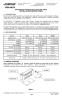
2 – 12
Chapter 3
3.1
Name and function of each part
Name and function of each part in master module
Name and function of each part
1] Lock button
2] LED display
Model name
EH-TRME2
Weight
Approx. 0.12 kg (0.26 lb)
Consumption current
(5VDC)
Approx. 200mA
Dimensions (mm (in.))
3] Rotary switch (upper)
30 (1.18)
4] Rotary switch (lower)
95 (3.74)
6] Front DIP switch
100 (3.94)
5] Reset switch
7] Connector (socket)
8] Side DIP switch
No.
Name
Function
Remarks
1]
Lock button
This is used when removing the module from base unit. After it is
installed to the base unit, the fixation can be reinforced using screws.
In this case, use M4 × 10 mm (0.39 in.) screw.
2]
LED display
The status of module is displayed on this LED.
See a table shown below.
3]
Rotary switch (upper)
This is a switch to set I/O assignment for master module.
See next page.
4]
Rotary switch (lower)
This is a switch to set the number of connected slave modules.
See next page.
5]
Reset switch
The module can be reset by pressing this switch when error such as
the module abnormal occurred.
See Section 6.4 for details.
6]
Front DIP switch
This is a switch to set an operation mode (HS refresh mode, etc.).
See next page or later.
7]
Connector
This is a connector to connect a twist-pair cable for connecting slave
See next page or later.
modules.
8]
Side DIP switch
This is a switch to set an operation mode (the last channel number of
See next page or later.
master, etc.).
Description of LED display
LED
LED
name
POW
REMOTE EH-TRME2
POW
TxD
RUN
RxD
HERR
CERR
RUN
TxD
RxD
HERR
CERR
Indication
Details
Power supply
Light up when 5V DC power is supplied to the module.
Light up in proper communication. (Light is turned off due to
Normal
time-out error when the communication with slave station is
communication
discontinued for 500ms or more.)
Transmission data
Light up according to transmission data from master station.
Received data
Light up according to received data from slave station.
Hardware error
Light up when hardware failure in master module is detected.
Light up during communication error. (Light is turned off
Communication error
automatically when communication is recovered.)
3–1
Chapter 3
Name and function of each part
Description of Rotary switch
Rotary switch
Symbol
Meaning
U
I/O
assignment
(Upper)
(Note 1)
U
I/O assignment of master module is set.
1
2
3
4 to 8
I/O assignment
of master
REMOTE
(RMM)
Y8W
X4Y4W
X8W
Undefined
9
X4Y4W
A
REMOTE2
B to C
E
F
Undefined
REMOTE2
Undefined
Set
0
CD
AB
E
9
F
8
0
7
1
65 32
4
MODE
L
Details of setting
CD
E
AB
9
F
8
0
7
1
65 32
4
Remarks
Maximum I/O points: 2,048 points / master
Available to EHV-CPU16/32/64/128
Maximum output points: 128 points / master
Maximum I/O points: 128 points / master
Maximum input points: 2,048 points / master
Maximum I/O points: 128 points / master
Also available to EH-CPU104A/208A/316A
Maximum I/O points: 1,024 points/master
Available to EH-CPU516/548 and
EHV-CPU16/32/64/128
In the case of mix with EM/EM-II station
-
[Default setting: U=A, L=0]
L
(Lower)
Number of Set the number of connected slave stations. Up to 12 units can be
slave stations connected. Set the number of the range from 1 to C.
(Note2)
(Note 1) The setting “9”, “A” and “E” are compatible operation mode with compact remote master module
(EH-TRMME).
And the setting “A” is operation mode that was expanded to 1,024 points (64 words).
(Note 2) In case of setting “A” and “E”, connectable remote slave modules are maximum 8 units.
Choose I/O assignment, depending on its CPU, master module operation mode, and slave module connection.
Master module operation mode can be changed using the DIP switch on the module front.
I/O assignment
CPU model
EH-CPU104A
EH-CPU208A
REMOTE
(RMM)
REMOTE2
(Note 1)
Y8W
X4Y4W
X8W
Compatible
mode
Compatible
mode
Compatible
mode
Compatible
mode
Compatible
mode
Compatible
mode
Compatible
or normal
mode
Compatible
mode
Compatible
mode
Compatible
mode
Compatible
or normal
mode
Compatible
mode
Compatible
mode
Compatible
mode
EH-CPU316A
EH-CPU516
EH-CPU548
EHV-CPU16
EHV-CPU32
EHV-CPU64
EHV-CPU128
Normal
mode
(Note 1) In case of an I/O assignment of "REMOTE2" for master module, if this module is
mixed together the slave module of the EM/EM-II series, set it in a compatible mode.
3–2
Chapter 3
Name and function of each part
Description of Front DIP switch
Symbol
HS
Setting description
HS (high-speed refresh mode)
selecting
HS
MODE
HOLD
TERM
4
3
2
1
ON
MODE
MODE
HS
Normal
mode
Compatible
mode
OFF
ON
OFF
ON
Transmission
interval
Approx. 100μs
Approx. 6μs
Approx. 100μs
Approx. 6μs
[Default setting: ON]
MODE (communication mode)
selecting
HS
MODE
HOLD
TERM
4
3
2
1
ON
HOLD
[Default setting: ON]
HOLD (input hold function)
selecting
HS
MODE
HOLD
TERM
4
3
2
1
Details
Refresh operation mode on remote communication is set (High-speed or
Low-speed).
In the case of all local stations are EH-TRMLE/TRLE2, the high-speed refresh
mode can be selectable.
The transmission interval of data changes by the setting of the refresh operation
mode. Refer to Section 4.8 for detail.
HS
OFF
Position
ON
Operation mode on remote communication for remote master module is set.
Compatible mode allows master module (EH-TRME2) to connect with slave
stations for series other than EH-150.
MODE
OFF
ON
Position
Position
OFF
TREM (built-in terminator insertion
/non-insertion) selecting
HS
MODE
HOLD
TERM
4
3
2
1
ON
It is selected whether the terminator build in the master module is inserted
between A and B terminals of the communication connector. The terminator has
to be inserted in both ends of master or slave module connected through a
twist-pair cable. 2 types of terminator “100Ω and 150Ω” are build in the master
module. It is possible to select which to insert by the side DIP switch.
TERM
ON
[Default setting: OFF]
Input hold function selection
Disable the input hold function (Turn off all input data from
slave at the communication error.)
Enable the input hold function (At the communication error,
input data from the slave is held with last data received
properly.)
ON
TERM
Communication mode selection
Normal mode
Compatible mode
When the communication time-out error occurred, it is selected whether the
input data from the slave is held or not. (Hold means the last data received
properly is fixed.)
HOLD
[Default setting: OFF]
Remote refresh mode selection
Low-speed refresh mode (for low-speed remote slave module)
High-speed refresh mode
(for high-speed remote modules for EH-150/EHV series)
Position
Selection of insertion / non-insertion of terminator
OFF
Not insert a built-in terminator. (in unnecessary case
because it is not both ends of a twist-pair cable)
ON
Insert a built-in terminator. (when it is both ends of a
twist-pair cable)
3–3
Chapter 3
Name and function of each part
ÇFlipping a DIP
figure shown in the right side.
switch up is ON.
1
2
3
4
5
6
7
8
O
When flipping a DIP switch up, it means ON as the
N
Description of Side DIP switch
Compatible mode setting
No.
Setting description
Details
1
Selecting the built-in
terminator value
100Ω or 150Ω terminator build in a master module, it is chosen which terminator is inserted
between A and B terminals of communication connector.
Bit8
ON
Position
Selection of built-in terminator
ON
100 Ω (for 0.3mm2 or 0.5mm2 recommended twist-pair cable)
OFF
1 2 3 4 5 6 7 8
1 2 3 4 5 6 7 8
ON
150 Ω (for 0.75mm2 recommended twist-pair cable)
ON
[Default setting: OFF]
2
Compression mode
selecting
ON
1 2 3 4 5 6 7 8
1 2 3 4 5 6 7 8
Enable/disable of the compression mode is chosen according to I/O assignment of master and slave
module. Refer to Chapter 4 for details of compression mode.
Bit7
Selection of
compression mode
Position
Master I/O
assignment
Y8W, X4Y4W, X8W
ON
OFF
Disable of compression mode
REMOTE2
1 2 3 4 5 6 7 8
[Default setting: OFF]
Local I/O assignment
Unnecessary
Depends on the I/O
assignment of the modules
ON
ON
Enable of compression mode
REMOTE2
X1Y1W (B1/1) in all slots
1 2 3 4 5 6 7 8
3
Setting the last
channel number of
master (Upper)
Upper digit of the last channel number for the master station is set. Set it in H00 to H3F ranges.
Refer to Chapter 4 for details.
Bit5
Bit6
OFF
OFF
Position
ON
Last
channel
No.
Bit5
Bit6
0
OFF
ON
ON
1 2 3 4 5 6 7 8
[Default setting:
all OFF]
ON
1 2 3 4 5 6 7 8
ON
OFF
1
ON
ON
1 2 3 4 5 6 7 8
4
Setting the last
channel number of
master (Lower)
2
1 2 3 4 5 6 7 8
ON
ON
Last
channel
No.
Position
3
1 2 3 4 5 6 7 8
Lower digit of the last channel number for the master station is set.
Bit1
Bit2
Bit3
Bit4
OFF
OFF
OFF
OFF
Position
Last
channel
No.
Bit1
Bit2
Bit3
Bit4
0
OFF
OFF
OFF
ON
ON
ON
OFF
OFF
OFF
ON
1
ON
OFF
OFF
ON
1 2 3 4 5 6 7 8
ON
OFF
OFF
ON
2
OFF
ON
OFF
ON
1 2 3 4 5 6 7 8
ON
OFF
OFF
ON
3
ON
ON
OFF
ON
1 2 3 4 5 6 7 8
OFF
ON
OFF
ON
4
OFF
OFF
ON
ON
1 2 3 4 5 6 7 8
OFF
ON
OFF
ON
5
ON
OFF
ON
ON
1 2 3 4 5 6 7 8
ON
ON
OFF
ON
6
OFF
ON
ON
ON
1 2 3 4 5 6 7 8
ON
ON
ON
OFF
ON
7
1 2 3 4 5 6 7 8
3–4
E
1 2 3 4 5 6 7 8
ON
[Default setting:
all OFF]
D
1 2 3 4 5 6 7 8
ON
OFF
C
1 2 3 4 5 6 7 8
ON
ON
B
1 2 3 4 5 6 7 8
ON
OFF
A
1 2 3 4 5 6 7 8
ON
ON
9
1 2 3 4 5 6 7 8
ON
OFF
8
1 2 3 4 5 6 7 8
ON
ON
Last
channel
No.
ON
1 2 3 4 5 6 7 8
1 2 3 4 5 6 7 8
Position
ON
ON
ON
ON
F
1 2 3 4 5 6 7 8
Chapter 3
Name and function of each part
Normal mode setting
No.
Setting description
Details
1
Selecting the built-in
terminator value
100Ω or 150Ω terminator build in a master module, it is chosen which terminator is inserted
between A and B terminals of communication connector.
Bit8
Position
Selection of built-in terminator
ON
ON
100 Ω (for 0.3mm2 or 0.5mm2 recommended twist-pair cable)
OFF
1 2 3 4 5 6 7 8
1 2 3 4 5 6 7 8
ON
[Default setting: OFF]
150 Ω (for 0.75mm2 recommended twist-pair cable)
ON
1 2 3 4 5 6 7 8
2
Setting the last
channel number of
master (Upper)
Upper digit of the last channel number for the master station is set. Set it in H00 to H7F ranges.
Refer to Chapter 4 for details.
Bit5
Bit6
Bit7
OFF
OFF
OFF
Position
ON
Last
channel
No.
Bit5
Bit6
Bit7
0
OFF
OFF
ON
ON
1 2 3 4 5 6 7 8
ON
1 2 3 4 5 6 7 8
[Default setting:
all OFF]
OFF
ON
OFF
1
ON
OFF
ON
1 2 3 4 5 6 7 8
ON
ON
OFF
2
OFF
ON
1 2 3 4 5 6 7 8
ON
ON
ON
OFF
3
ON
ON
ON
1 2 3 4 5 6 7 8
3
Setting the last
channel number of
master (Lower)
ON
6
ON
1 2 3 4 5 6 7 8
ON
5
1 2 3 4 5 6 7 8
ON
OFF
4
1 2 3 4 5 6 7 8
ON
ON
7
1 2 3 4 5 6 7 8
Lower digit of the last channel number for the master station is set.
Bit1
Bit2
Bit3
Bit4
OFF
OFF
OFF
OFF
Position
Last
channel
No.
Bit1
Bit2
Bit3
Bit4
0
OFF
OFF
OFF
ON
ON
OFF
OFF
OFF
ON
OFF
OFF
ON
OFF
OFF
ON
2
OFF
ON
OFF
ON
1 2 3 4 5 6 7 8
ON
OFF
OFF
ON
3
ON
ON
OFF
ON
1 2 3 4 5 6 7 8
OFF
ON
OFF
ON
4
OFF
OFF
ON
ON
1 2 3 4 5 6 7 8
OFF
ON
OFF
ON
5
ON
OFF
ON
ON
1 2 3 4 5 6 7 8
ON
ON
OFF
ON
6
OFF
ON
ON
ON
1 2 3 4 5 6 7 8
ON
ON
OFF
ON
7
1 2 3 4 5 6 7 8
E
1 2 3 4 5 6 7 8
ON
ON
D
1 2 3 4 5 6 7 8
ON
OFF
C
1 2 3 4 5 6 7 8
ON
ON
B
1 2 3 4 5 6 7 8
ON
OFF
A
1 2 3 4 5 6 7 8
ON
ON
9
1 2 3 4 5 6 7 8
ON
ON
8
ON
1
1 2 3 4 5 6 7 8
OFF
Last
channel
No.
1 2 3 4 5 6 7 8
ON
ON
Position
ON
1 2 3 4 5 6 7 8
1 2 3 4 5 6 7 8
[Default setting:
all OFF]
Last
channel
No.
Position
ON
ON
ON
ON
F
1 2 3 4 5 6 7 8
[Caution of the switch setting]
- The setting of the compression mode is not possible with the normal mode.
- In case that the switch setting is the undefined, HERR LED may light up.
- In case that the I/O assignment is "X4Y4W" or "Y8W" in the master station, the external outputs on slave
station may not be maintained regardless of HOLD selecting when power supply turns off in the master
station.
3–5
Chapter 3
Name and function of each part
3.2
Name and function of each part in slave module
Name and function of each part
1] Lock button
2] LED display
Model name
EH-TRLE2
Weight
Approx. 0.14 kg (0.30 lb)
Consumption current
Approx. 200mA
(5VDC)
Dimensions (mm (in.))
3] Rotary switch
(upper)
4] Rotary switch
(lower)
45 (1.77)
95 (3.74)
100 (3.94)
5] Reset switch
6] Front DIP switch
7] Communication
connector
8] Bottom DIP switch
No.
Name
1]
Lock button
2]
3]
4]
LED display
Rotary switch (upper)
Rotary switch (lower)
5]
Reset switch
6]
Front DIP switch
Communication
connector
7]
8]
Bottom DIP switch
Function
This is used when removing the module from base unit. After it is
installed to the base unit, the fixation can be reinforced using
screws. In this case, use M4 × 10 mm (0.39 in.) screw.
The status of module is displayed on this LED.
This is a switch to set the station No.
This is a switch to set the number of occupancy slots.
The module can be reset by pressing this switch when error such
as the module abnormal occurred.
This is a switch to set an operation mode (HS refresh mode, etc.).
This is a connector to connect a twist-pair cable for
communication.
This is a switch to set an operation mode (the first slave number
of slave, etc.).
Remarks
See a table shown below
See next page
See next page
See Section 6.4 for details.
See next page
See next page or later.
See next page or later.
Description of LED display
LED
name
LED
POW
REMOTE EH-TRLE2
POW
TxD
HERR
RUN
RxD
CERR
Indication
Details
Power supply
Light up when 5V DC power is supplied to the module.
Light up in proper communication. (Light is turned off due to
Normal
time-out error when the communication with slave station is
RUN
communication
discontinued for 500ms or more.)
TxD Transmission data Light up according to transmission data from slave station.
RxD Received data
Light up according to received data from master station.
HERR Hardware error
Light up when hardware failure in master module is detected.
Communication
Light up during communication error. (Light is turned off
CERR
error
automatically when communication is recovered.)
3–6
Chapter 3
Name and function of each part
Description of Rotary switch
Rotary switch
U
MODE
L
Symbol
U
(Upper)
CD
AB
E
9
F
8
0
7
1
65 32
4
CD
E
AB
9
F
8
0
7
1
65 32
4
Meaning
Details of setting
Station No.
The station No. of the slave modules is set from 0 to B (Hex).
(0 to B)
In the case of mix with EM/EM-II station, set E in spite of
Mix with EM mode station No..
(E)
L
(Lower)
Number of
occupancy slots
(1 to B units)
The number of occupancy slots used in the slave station is set
from 1 to B.
[Default setting: U=0, L=0]
Description of Front DIP switch
Symbol
HS
Setting description
HS (high-speed refresh mode)
selecting
HS
MODE
HOLD
TERM
4
3
2
1
ON
MODE
MODE
HS
Normal
mode
Compati
ble mode
OFF
ON
OFF
ON
Transmission
interval
Approx. 100μs
Approx. 6μs
Approx. 100μs
Approx. 6μs
[Default setting: ON]
MODE (communication mode)
selecting
HS
MODE
HOLD
TERM
4
3
2
1
ON
HOLD
[Default setting: ON]
HOLD (output hold function)
selecting
HS
MODE
HOLD
TERM
4
3
2
1
Details
Refresh operation mode on remote communication is set (High-speed or
Low-speed).
In the case of all stations consist from remote modules for EH-150/EHV series,
the high-speed refresh mode can be selectable.
The transmission interval of data changes by the setting of the refresh operation
mode. Refer to Section 4.8 for detail.
HS
OFF
Position
ON
Operation mode on remote communication for remote slave module is set.
Compatible mode allows slave module (EH-TRLE2) to connect with
master/slave stations for series other than EH-150.
MODE
OFF
ON
Position
Position
OFF
TREM (built-in terminator
insertion / non-insertion) selecting
HS
MODE
HOLD
TERM
4
3
2
1
ON
ON
It is selected whether the terminator build in the slave module is inserted
between A and B terminals of the communication connector. The terminator has
to be inserted in both ends of master or slave module connected through a
twist-pair cable. 2 types of terminator “100Ω and 150Ω” are built in the slave
module. It is possible to select which to insert by the bottom DIP switch.
The built-in terminator is disconnected when power supply is turned off. So,
please set TERM off and connect external terminator to communication
connector when you use fallback operation.
TERM
[Default setting: OFF]
Output hold function selection
Disable the output hold function (Turn off all output data
from the master at the communication error.)
Enable the output hold function (At the communication
error, output data from the master is held with last data
received properly.)
ON
TERM
Communication mode selection
Normal mode
Compatible mode
When the communication time-out error occurred, it is selected whether the
output data from the master is held or not. (Hold means the last data received
properly is fixed.)
HOLD
[Default setting: OFF]
Remote refresh mode selection
Low-speed refresh mode (for low-speed remote modules)
High-speed refresh mode
(for high-speed remote modules for EH-150/EHV series)
Position
Selection of insertion / non-insertion of terminator
OFF
Not insert a built-in terminator. (in unnecessary case
because it is not both ends of a twist-pair cable)
ON
Insert a built-in terminator. (when it is both ends of a
twist-pair cable)
3–7
Chapter 3
Name and function of each part
Description of Bottom DIP switch
L Flipping a DIP
ON
switch down is ON
When flipping a DIP switch down, it means ON
as the figure shown in the left side.
1 2 3 4 5 6 7 8
Compatible mode setting
Setting description
Details
100Ω or 150Ω terminator build in a slave module, it is chosen which terminator is inserted
between A and B terminals of a connection connector.
OFF
ON
ON
[Default setting: OFF]
Enable/disable of the compression mode is chosen according to I/O assignment of master module.
Refer to Chapter 4 for details of compression mode.
Position
ON
ON
Upper digit of the first channel number for the slave station is set. Set it in H00 to H3F ranges.
Refer to Chapter 4 for details.
Bit5
Bit6
OFF
OFF
ON
OFF
Position
all OFF]
Bit6
0
OFF
ON
1
ON
ON
First
channel
No.
Position
2
1 2 3 4 5 6 7 8
3
1 2 3 4 5 6 7 8
Lower digit of the first channel number for the slave station is set.
ON
OFF
ON
OFF
ON
OFF
ON
OFF
ON
ON
OFF
OFF
ON
ON
OFF
OFF
OFF
ON
ON
ON
ON
OFF
OFF
OFF
OFF
OFF
OFF
OFF
Bit3
Bit4
0
OFF
OFF
OFF
ON
1 2 3 4 5 6 7 8
1
ON
OFF
OFF
ON
1 2 3 4 5 6 7 8
2
OFF
ON
OFF
ON
1 2 3 4 5 6 7 8
3
ON
ON
OFF
ON
1 2 3 4 5 6 7 8
4
OFF
OFF
ON
ON
1 2 3 4 5 6 7 8
5
ON
OFF
ON
ON
1 2 3 4 5 6 7 8
6
OFF
ON
ON
ON
1 2 3 4 5 6 7 8
7
1 2 3 4 5 6 7 8
3–8
ON
ON
ON
ON
Position
ON
OFF
Bit2
ON
OFF
Bit1
ON
OFF
First
channel
No.
ON
OFF
Position
ON
Bit4
ON
Bit3
ON
Bit2
ON
Bit1
1 2 3 4 5 6 7 8
[Default setting:
all OFF]
Bit5
1 2 3 4 5 6 7 8
ON
ON
Setting the first channel
number of slave
(Lower)
First
channel
No.
1 2 3 4 5 6 7 8
ON
[Default setting:
1 2 3 4 5 6 7 8
ON
1 2 3 4 5 6 7 8
ON
1 2 3 4 5 6 7 8
ON
ON
Setting the first channel
number of slave
(Upper)
OFF
ON
[Default setting: OFF]
4
Selection of compression mode
Disable of compression mode
(In this case, we can use the number of I/O modules equal to
the number of occupancy slots of slave module setting with
rotary switch)
Enable of compression mode
(In this case, we can use the number of I/O modules equal to
the double number of occupancy slots of slave module setting
with rotary switch.)
1 2 3 4 5 6 7 8
ON
ON
Bit7
3
150Ω (for 0.75mm2 recommended twist-pair cable)
1 2 3 4 5 6 7 8
ON
Compression mode
selecting
100Ω (for 0.3mm2 or 0.5mm2 recommended twist-pair cable)
1 2 3 4 5 6 7 8
ON
2
Selection of built-in terminator
ON
1 2 3 4 5 6 7 8
Position
ON
ON
Bit8
ON
Selecting built-in
terminator value
ON
1
ON
No.
First
channel
No.
8
1 2 3 4 5 6 7 8
9
1 2 3 4 5 6 7 8
A
1 2 3 4 5 6 7 8
B
1 2 3 4 5 6 7 8
C
1 2 3 4 5 6 7 8
D
1 2 3 4 5 6 7 8
E
1 2 3 4 5 6 7 8
F
1 2 3 4 5 6 7 8
Chapter 3
Name and function of each part
Normal mode setting
Setting description
Details
100Ω or 150Ω terminator build in a slave module, it is chosen which terminator is inserted
between A and B terminals of a connection connector.
OFF
ON
ON
[Default setting: OFF]
Upper digit of the first channel number for the slave station is set. Set it in H00 to H7F ranges.
Refer to Chapter 4 for details.
OFF
OFF
OFF
ON
OFF
OFF
Position
ON
Setting the first channel
number of slave
(Lower)
ON
OFF
OFF
Bit5
Bit6
Bit7
0
OFF
OFF
ON
1 2 3 4 5 6 7 8
1
ON
OFF
ON
1 2 3 4 5 6 7 8
2
OFF
ON
ON
1 2 3 4 5 6 7 8
3
ON
ON
Position
ON
1 2 3 4 5 6 7 8
First
channel
No.
4
1 2 3 4 5 6 7 8
5
1 2 3 4 5 6 7 8
6
1 2 3 4 5 6 7 8
7
1 2 3 4 5 6 7 8
Lower digit of the first channel number for the slave station is set.
Bit1
Bit2
Bit3
Bit4
OFF
OFF
OFF
OFF
Position
First
channel
No.
Bit1
Bit2
Bit3
Bit4
0
OFF
OFF
OFF
ON
1 2 3 4 5 6 7 8
Position
First
channel
No.
8
1 2 3 4 5 6 7 8
OFF
ON
OFF
ON
ON
ON
ON
ON
OFF
OFF
OFF
OFF
2
OFF
ON
OFF
ON
1 2 3 4 5 6 7 8
3
ON
ON
OFF
ON
1 2 3 4 5 6 7 8
4
OFF
OFF
ON
ON
1 2 3 4 5 6 7 8
5
ON
OFF
ON
ON
1 2 3 4 5 6 7 8
6
OFF
ON
ON
ON
1 2 3 4 5 6 7 8
7
1 2 3 4 5 6 7 8
ON
ON
ON
ON
ON
ON
ON
ON
OFF
ON
ON
OFF
OFF
ON
ON
OFF
OFF
OFF
ON
ON
OFF
ON
OFF
1
1 2 3 4 5 6 7 8
ON
ON
ON
OFF
ON
OFF
OFF
ON
[Default setting:
all OFF]
OFF
ON
ON
ON
1 2 3 4 5 6 7 8
ON
ON
3
ON
ON
OFF
ON
all OFF]
First
channel
No.
ON
Bit7
ON
Bit6
ON
Bit5
ON
[Default setting:
150Ω (for 0.75mm2 recommended twist-pair cable)
1 2 3 4 5 6 7 8
ON
1 2 3 4 5 6 7 8
100Ω (for 0.3mm2 or 0.5mm2 recommended twist-pair cable)
ON
Setting the first channel
number of slave
(Upper)
ON
2
Selection of built-in terminator
1 2 3 4 5 6 7 8
ON
1 2 3 4 5 6 7 8
Position
ON
ON
Bit8
ON
Selecting built-in
terminator value
ON
1
ON
No.
9
1 2 3 4 5 6 7 8
A
1 2 3 4 5 6 7 8
B
1 2 3 4 5 6 7 8
C
1 2 3 4 5 6 7 8
D
1 2 3 4 5 6 7 8
E
1 2 3 4 5 6 7 8
F
1 2 3 4 5 6 7 8
[Caution of the switch setting]
- The setting of the compression mode is not possible with the normal mode.
- In case that the switch setting is the undefined, HERR LED may light up.
- In case that the I/O assignment is "X4Y4W" or "Y8W" in the master station, the external outputs on slave
station may not be maintained regardless of HOLD selecting when power supply turns off in the master
station.
3–9
Chapter 3
Name and function of each part
MEMO
3 – 10
Chapter 4 Basic functions and System configuration
4.1 Method of using compact remote2 and selection of CPU
There are three methods to use compact remote2 system by I/O assignment of master or slave module.
(1) Normal remote method
(2) Compression remote method
(3) External I/O method
Differences between these methods are shown in Table 4.1.1. I/O assignment of master or slave module determines
the number of maximum mountable master modules on basic unit, the number of maximum slave stations per master
module and maximum remote I/O points. Normal remote method has 2,048 points per master module for remote I/O
and free location of input modules and output modules on slave station. I/O assignment “REMOTE (RMM)” is usable
up to 2,048 points, and is supported by EHV-CPU. Therefore we recommend EHV-CPU for compact remote2 system.
Table 4.1.1 Using method of compact remote2 for each CPU
CPU module
Method of using
compact remote2
Normal remote method
Selection purpose
For new design, and replacement
without image slot
Communication mode
Master
Compression
mode setting
Slave
I/O assignment of master
I/O assignment of slave
Reference
section
Number of mountable
master module
Number of connectable
slave modules
Number of occupied
channels in master
Input
Number of
I/O points
Output
Special internal outputs for
remote function
Operation parameters for
remote function
EHV-CPU16/32/64/128
EH-CPU516/548
EH-CPU104A/208A/316A
Compression
External I/O method
remote method
For mounting 5 or more master
modules, or using of
EH-CPU104A/208A/316A
ON (Compatible mode)
OFF
ON
OFF
For replacement
with image slot
OFF (Normal mode)
OFF
ON
OFF
ON
REMOTE
REMOTE2
(RMM)
X16, X32, X64, Y16, Y32, Y64,
X1Y1W (B1/1)
X4W, X8W, Y4W, Y8W, Empty
for all slots
X4Y4W
X8W
Unnecessary
Not limited
(according to CPU)
4 units / CPU
12 units / master
Y8W
8 units / master
4 units /
master
8 units / master
8
128
64
32
4
I/O 2,048 points
(Free location)
I/O 1,024 points
(Free location)
512 points
512 points
64 points
64 points
128 points
128 points
Available (Note 1)
Not available
Not available (Note 2)
Not available
Basic system
Section 4.3.1
Section 4.3.2
-
Section
4.3.4
Section
4.3.3
Section
4.3.5
Replace of H-200
-
Section 4.4.1
Section 4.4.2
Replace of large H
-
Section 4.5.4
-
-
Section
4.5.2
-
Section
4.5.1
-
Section
4.5.3
Replace of EM
-
Section 4.6.1
Section 4.6.2
-
-
-
(Note 1) Please refer to Section 6.2 for detail of special internal outputs for remote function
(Note 2) Please refer to Section 6.3 for detail of operation parameters for remote function.
4–1
Chapter 4
Basic functions and System configuration
In the case of using EH-CPU516/548 for cost reduction, please set “REMOTE2” for I/O assignment of master
module as normal remote method. You can build the remote system to 1,024 points if you do so. In addition,
choose external I/O method when you build the small scale system or build external I/O in the slightly remote
place in EH-CPU104A/208A/316A.
In the case of I/O assignment for external I/O method "Y8W", “X4Y4W” or "X8W" there is a disadvantage of
not using special internal outputs indicating remote refresh cycle time and so on. On the other hand, there is an
advantage of not limiting it to the number of mounting of master modules per CPU. Therefore, you can construct
large-scale remote system with twisted pair cable by use many master modules per CPU.
4–2
Chapter 4
4.2
Basic functions and System configuration
Basic functions of compact remote2
4.2.1
Channels and remote I/O area
(1) Channels
The channel is the unit of transmitted and received data between master module (EH-TRME2) and slave
module (EH-TRLE2). One channel consists from 16 bit (1 word) input area and 16 bit (1 word) output
area as shown in Figure 4.2.1.
(2) Remote I/O area
The master module (EH-TRME2) and the slave module (EH-TRLE2) have remote I/O area as shown in
Figure 4.2.1.
Rem ote I/O area
Channel
No.
Input
Output
00
01
02
03
04
05
06
07
Composition of one channel
:
:
Input
Output
16 bits (1 word)
16 bits (1 word)
128 channels
:
:
7A
7B
7C
7D
7E
7F
Figure 4.2.1 Composition of remote I/O area and one channel
The configuration of the remote I/O area of master station is different by a set I/O assignment. Refer to
Section 4.2.4 or later about the details of the remote I/O area in each I/O assignment.
4.2.2
Master number and slave station number
(1) Master number (Master No.)
Maximum four compact remote2 master modules (EH-TRME2) can be mounted on slots those slot
number are 0 to 7 as shown in Figure 4.2.2 in the case of setting I/O assignment “REMOTE2”, “REMOTE
(RMM)” of master module. In this case remote master number is sequentially allocated from one near
CPU from 1 to 4. I/O No. on remote slave base are determined according to this master number. Please
refer to Section 4.3.1 for I/O No. on remote slave base.
M aster
M aster
M aster
M aster
Slot No.
0
1
2
3
4
5
6
7
8
9
No.1
No.2
No.3
No.4
A
M ountable slots (0 to 7)
Figure 4.2.2 Mountable slots for master module and master number
4–3
Sequentially
allocated from
one nearer to
CPU m odule
Chapter 4
Basic functions and System configuration
(2) Slave station number (Slave St. No.)
Please set slave station number 0 to B to compact remote2 slave module (EH-TRLE2) with rotary switch
(U) unlike old model slave module (RIOH-TL, RIOM-TL, etc) for the slave station identification.
In this case, please set not to overlap slave station number. "Slave station number" is abbreviated at the
following, "Slave St. No.".
Slave St. No.0
Remote slave (EH -TRLE2)
Slave St. No.1
Remote slave (EH -TRLE2)
Slave St. No.2
Remote slave (EH -TRLE2)
Figure 4.2.3 Slave station number (Slave St. No.)
4.2.3
Occupied channels and method of appointing
(1) Occupied channels
The area used respectively in compact remote2 master module (EH-TRME2) and slave module
(EH-TRLE2) is called an occupied channels. Figure 4.2.4 shows the example of the occupied channels of
one master and two slave stations. The number of occupied channels used in the slave module is decided
according to the number of I/O modules mounted on the slave base. Moreover, the number of occupied
channels of master module is matched to the total of the number of occupied channels of all slave modules.
The occupied channels of slave modules not overlap between slave modules.
(2) Transmission range of remote communication
Occupied channels of master and slave are always refreshed to the same data by remote communication.
Unused channels are not transmitted by remote communication. Therefore, the remote refresh time
depends on the number of occupied channels of master module as the formula 4.2 to 4.3 in Section 4.8
(3) Specification method of occupied channels
Please set last channel number with side DIP switch for occupied channels of master module. And for
occupied channels of slave module, please set first channel number with bottom DIP switch and occupied
slots with front rotary switch (L). Please refer to Chapter 3 for details of each switch.
Rem ote I/O area in m aster
Channel
No.
0
1
2
3
4
5
6
Channel
No.
Input
Output
(8 channels)
7
8
9
A
B
C
D
E
F
Unused channels
(8 channels)
Last channel N o.: 7
Input
Output
0
Rem ote
com m unication 1
Occupied channels
Rem ote I/O area in
Slave St. No.0
2
3
4
5
6
7
8
9
A
B
C
D
E
F
Occupied channels
(5 channels)
Rem ote com m unication
U nused channels
(11 channels)
Channel
No.
0
1
2
3
4
5
6
7
8
9
A
B
C
D
E
F
First channel N o.: 0
O ccupied slots: 5
Figure 4.2.4 Occupied channels and remote communication
4–4
Rem ote I/O area in
Slave St. No.1
Input
Output
U nused channels
(5 channels)
Occupied channels
(3 channels)
U nused channels
(8 channels)
First channel N o.: 5
O ccupied slots: 3
Chapter 4
4.2.4
Basic functions and System configuration
Correspondence of occupied channels and I/O slots (Normal remote method)
In the case of normal remote method I/O data are stored in occupied channels according to I/O assignment for
remote base as shown in Figure 4.2.5. One channel corresponds to one word because only either of them is used
among I/O in one channel. It is allocated from the order with small channel number since slot No.0 of the slave
base. Maximum 11 I/O modules can be mounted on the one slave base
I/O assignment
“REMOTE (RMM)”
Output area
Input area
Channel
number
H00
(Transmission)
Valid
Channel
number
H00
(Reception)
I/O assignment
“REMOTE2”
Output area
Input area
(Transmission)
(Reception)
Valid
Valid
Invalid
Invalid
Invalid
Invalid
Last
channel
Valid
H3F
Last
channel
Invalid
Invalid
H7F
H7F
The remote I/O area has H00 to H7F channels
(128 channels). The area to be used is secured
by setting the last channel number using the
dipswitch on the module.
The remote I/O area has H00 to H3F channels
(64 channels). The area to be used is secured by
setting the last channel number using the
dipswitch on the module.
Figure 4.2.5 Configuration of normal remote method
In the normal remote method, I/O is occupied according to I/O assignment of the slave station in turn
from first channel. You cannot use the input area of the channel occupied as output or the output area of
the channel occupied as input.
I/O assignment for
remote base
Slot No.
0 1 2
X X Y
16 16 16
Occupied channels of slave
St.No.0
Occupied channels of master
CPU
Channel
No.
CPU
I/O refresh
0
1
2
3
4
5
6
7
Input
X10000~
X10100~
-
-
-
X11200~
X11300~
-
Output
-
-
Y10200~
Y11000~
Y11100~
-
-
Y11400~
Channel
No.
0
Remote
communication 1
2
Input
X10000~
X10100~
-
Output
-
-
Y10200~
Figure 4.2.6 Correspondence of occupied channels and I/O slots
4–5
Slave I/O
refresh
Chapter 4
4.2.5
Basic functions and System configuration
Compression mode of master module (Compression remote method)
In the case of old models H-200/250/252B/252C, input data and output data are stored in one channel by setting
I/O assignment “X1Y1W (B1/1)” as shown in left side of Figure 4.2.8. In the case of EH-150 (include EHV) series,
input data and output data are stored in separate channel by setting I/O assignment “X1Y1W (B1/1)” as shown in
right side of Figure 4.2.8. In order to replace old models to EH-150 with compatibility, you can set master module
with compression mode, and can compress one word of input data and one word of output data into one channel as
shown in Figure 4.2.9. You can replace old models to EH-150 (include EHV) with no change in I/O number for
slot on slave base by setting master and slaves compression mode. Please refer to Section 4.4.2 for example of
replacement with compression mode.
Similarly in the case of EM/EM-II series, there is a function that input data and output data are stored in one
channel, and slave module outputs the output data to image slots. In this case it is convenient to setting
compression mode as Section 4.6.2.
Channel
number
H00
I/O assignment
“REMOTE2”
Output area
Input area
(Transmission)
(Reception)
Valid
Valid
The compression remote method is operation
mode handling the output and input as pair in the
same channel. Therefore the number of the channels
Last
channel
is 32, but remote I/O points are 1,024 points.
Therefore, transmission refreshment time is half
because the number of channels is reduced to half.
Invalid
Invalid
Invalid
Invalid
H1F
H3F
Both input and output area owns 32
channels from H00 to H1F. The area to be
used is secured by setting the last channel
number using the dipswitch on the module.
Figure 4.2.7 Configuration of compression remote method
4–6
Chapter 4
I/O assignment for
remote base
I/O assignment for
remote base
Occupied channels of master
H-200
CPU
Channel
No.
CPU
I/O refresh
0
1
2
3
Basic functions and System configuration
Input
X10000~
X10100~
X10200~
X10300~
Occupied channels of master
EH-150
CPU
Output
Y10016~
Y10116~
Y10216~
Y10316~
Channel
No.
CPU
I/O refresh
0
1
2
3
4
5
6
7
Input
X10000~
-
X10100~
-
X10200~
-
X10300~
-
Output
-
Y10016~
-
Y10116~
-
Y10216~
-
Y10316~
Compression mode of master: OFF
(Master stores 8 slots to 8 channels)
Figure 4.2.8 Difference point of H-200 and EH-150 in the case of assignment “X1Y1W (B1/1)” for remote base
I/O assignment for
remote base
Image slots (Output module only)
Occupied slots (Input module only)
Slot No.
0 1 2 3 4 5 6 7
X X X X Y Y Y Y
16 16 16 16 16 16 16 16
CPU
Occupied channels of slave
Occupied channels of master
Channel
No.
CPU
I/O refresh
0
1
2
3
Input
X10000~
X10100~
X10200~
X10300~
Output
Y10016~
Y10116~
Y10216~
Y10316~
Channel
No.
0
Remote
communication 1
2
3
Compression mode of master: ON
(Master compress 8 slots to 4 channels)
Input
X10000~
X10100~
X10200~
X10300~
Output
Y10016~
Y10116~
Y10216~
Y10316~
Compression mode of slave: ON
(Slave compress 8 slots to 4 channels)
Slave
I/O refresh
Figure 4.2.9 Correspondence of occupied channels and I/O slots (Compression remote method)
4–7
Chapter 4
Basic functions and System configuration
4.2.6
External I/O method (X4Y4W) (Compression mode of slave module)
In the case of external I/O method (X4Y4W), CPU module stores I/O data in occupied channels of master
module as shown in Figure 4.2.11. Data is stored in both the input and the output in one channel unlike a normal
remote method. The compression mode of slave module is a mode that compresses the data of the occupied slots
and the image slots into half the occupied channels of the number of slots to correspond to this as shown in Figure
4.2.11. Therefore, you can use image slots of the same number as the occupied slots. It is allocated from the order
with small channel number since slot No.0 of occupied slots of the slave base. It is allocated from the order with
small channel number since slot No.2 of image slots of the slave base. Only input modules are mounted on the
occupied slots, and only output modules are mounted on the image slots of slave base. The output module installed
in the occupied slot doesn't operate.
Channel
number
H00
H03
(Fixed)
I/O assignment
“X4Y4W”
Output area
Input area
(Transmission)
(Reception)
Valid
Valid
The external I/O method (X4Y4W) is operation
mode handling the output and input as pair in the
same channel. The number of the usable channels is
4. In this mode, the output area is from WY*4 to
WY*7, and the input area is from WX*0 to WX*3.
Invalid
Invalid
H3F
Both input and output area owns 4
channels from H00 to H03. Number of
usable channel and the area are fixed.
Figure 4.2.10 Configuration of external I/O method (X4Y4W)
Image slot (Output module only)
I/O assignment for
remote base
Occupied slots (Input module only)
Unnessesary
(Remote I/O No. is
determined by
mounted slot No. of
master module)
CPU
Slot No.
0 1 2
X X Y
16 16 16
Occupied channels of master
(Example of master is mounted on slot 2)
Channel
No.
CPU
I/O refresh
0
1
2
3
Input
X200~215
X216~231
X232~247
X248~263
Output
Y264~279
Y280~295
WY26
WY27
Occupied channels of slave
Channel
No.
Remote
Communication
0
1
Input
X200~215
X216~231
Output
Y264~279
Y280~295
Slave I/O
refresh
Compression mode of slave: ON
(Slave compresses 4 slots to 2 channels)
Figure 4.2.11 Correspondence of occupied channels and I/O slots in slave with compression mode
4–8
Chapter 4
4.2.7
Basic functions and System configuration
External I/O method (Y8W, X8W)
In the case of external I/O method (Y8W, X8W), CPU module stores I/O data in occupied channels of master
module as shown in Figure 4.2.13 or Figure 4.2.14.
Channel
number
H00
I/O assignment “Y8W”
Output area
Input area
(Transmission)
Channel
number
H00
(Reception)
Valid
H07
(Fixed)
I/O assignment “X8W”
Output area
Input area
(Transmission)
(Reception)
Valid
H07
(Fixed)
Invalid
Invalid
Invalid
H3F
Only the output area uses 0 to 7 channels
(8 channels). The number of channels and
areas are fixed.
Invalid
H3F
Only the input area uses 0 to 7 channels (8
channels). The number of channels and
areas are fixed.
Figure 4.2.12 Configuration of external I/O method (Y8W, X8W)
I/O assignment for
remote base
Slot No.
0 1 2 3 4 5 6 7
Y
Y Y Y Y Y Y Y Y
16 16 16 16 16 16 16 16
Y
Y
CPU
Occupied channels of slave
Occupied channels of master
Channel
No.
CPU
I/O refresh
0
1
2
3
4
5
6
7
Input
Channel
Remote No.
Output
Y10000~ communication 0
1
Y10100~
2
Y10200~
3
Y10300~
4
Y10400~
5
Y10500~
6
Y10600~
7
Y10700~
Compression mode of master: OFF
Input
Output
Y10000~
Y10100~
Y10200~
Y10300~
Y10400~
Y10500~
Y10600~
Y10700~
Slave I/O
refresh
Compression mode of slave: OFF
Figure 4.2.13 Correspondence of occupied channels and I/O slots in slave with external I/O method (Y8W)
4–9
Chapter 4
Basic functions and System configuration
I/O assignment for
remote base
リモート先 I/O 割付
Slot No.
0 1 2 3 4 5 6 7
X X X X X X X X
16 16 16 16 16 16 16 16
CPU
Occupied channels of slave
Occupied channels of master
Channel
No.
CPU
I/O refresh
0
1
2
3
4
5
6
7
Input
X10000~
X10100~
X10200~
X10300~
X10400~
X10500~
X10600~
X10700~
Output
Channel
Remote No.
communication 0
1
2
3
4
5
6
7
Compression mode of master: OFF
Input
X10000~
X10100~
X10200~
X10300~
X10400~
X10500~
X10600~
X10700~
Output
Slave I/O
refresh
Compression mode of slave: OFF
Figure 4.2.14 Correspondence of occupied channels and I/O slots in slave with external I/O method (X8W)
4 – 10
Chapter 4
4.2.8
Basic functions and System configuration
Occupied channels of EH-TRLE2
EH-TRLE2 occupies allocated total channels from set first channel number according to the I/O assignment of
modules implemented.
Usable to EH-BS11A
Slot No.
0 1 2 3 4 5 6 7 8 9 A
X X X X X Y Y Y Y Y Y
8 8 8 8 8 8 8 8 8 8 8
W W W W W W W W W W W
Channel
number
H00
First
channel
EH-TRLE2
Output area
Input area
(Transmission)
(Reception)
Valid
Valid
Occupied channels of slave St No. 0 (First channel 00)
Channel
number
00~07
08~0F
10~17
18~1F
20~27
28~2F
30~37
38~3F
40~47
48~4F
50~57
Input
WX1000~WX1007
WX1010~WX1017
WX1020~WX1027
WX1030~WX1037
WX1040~WX1047
Output
Last
channel
WY1050~WY1057
WY1060~WY1067
WY1070~WY1077
WY1080~WY1087
WY1090~WY1097
WY10A0~WY10A7
H7F
Both input and output area owns total channels
according to the I/O assignment of modules
implemented from set first channel from H00 to
H7F. Slave is able to occupy up to 88 channels.
Figure 4.2.15 Correspondence of occupied channels and I/O slots in slave
4 – 11
Chapter 4
4.3
Basic functions and System configuration
Basic system configuration
Basic system configurations consist from remote master module (EH-TRME2) and remote slave modules
(EH-TRLE2) are shown in Section 4.3.1 and 4.3.2.
4.3.1
Basic system configuration (REMOTE(RMM) method)
Basic system configuration example that I/O assignment of master module (EH-TRME2) is “REMOTE (RMM)”
is shown in Figure 4.3.1. The last channel number is abbreviated to “Last CH.”, and the first channel number is
abbreviated to “First CH” in the following figures of setting for DIP switch.
U
0
L
3
ON
1 2 3 4
I/O assignment: 0
REMOTE(RMM)
U
Number of slave:
3
L 8
HS: ON
MODE: OFF
HOLD: ON
TERM: ON
0
Slave St No: 0
U
Number of
occupied
slots: 8
HS: ON
MODE: OFF
HOLD: ON
TERM: OFF
ON
1 2 3 4
Setting of slave St No.2
Setting of slave St No.1
Setting of slave St No.0
Setting of master No.1
1
L
Slave St No: 1
5
ON
1 2 3 4
Slave St No: 2
U
2
Number of
occupied
slots: 5
HS:ON
MODE:OFF
HOLD:ON
TERM:OFF
L
3
ON
1 2 3 4
Number of
occupied
slots: 3
HS:ON
MODE:OFF
HOLD:ON
TERM:ON
First CH: 20
1 2 3 4 5 6 7 8
ON
First CH: 00
1 2 3 4 5 6 7 8
ON
Last CH: 3F
1 2 3 4 5 6 7 8
ON
ON
First CH: 34
1 2 3 4 5 6 7 8
Remote master (EH-TRME2): Maximum 4 modules mountable (Slot No.0 to 7)
Master number is sequentially allocated from one near CPU from 1 to 4.
Remote slave (EH-TRLE2)
X
Y
X X X X 8 Y Y 8
16 16 32 64 W 64 64 W
X10000~X1BA95
Y10000~Y1BA95
Occupied channel of master No.1
Channel
No.
00
01
02-03
04-07
08-0F
10-13
14-17
18-1F
20
21
22-23
24-2B
2C-33
34-37
38-3B
3C-3F
Input
X10000~
X10100~
X10200~
X10300~
WX1040~
-
-
-
-
-
X11200~
WX1130~
-
X12000~
-
-
Output
-
-
-
-
-
Y10500~
Y10600~
WY1070~
Y11000~
Y11100~
-
-
WY1140~
-
Y12100~
Y12200~
X Y
Y Y X 8 8
16 16 32 W W
/WX1000~WX1BA7
/WY1000~WY1BA7
X20000~X2BA95
Y20000~Y2BA95
X30000~X3BA95
Y30000~X3BA95
X40000~X4BA95
Y40000~X4BA95
X Y Y
64 64 64
/WX2000~WX2BA7
/WY2000~WY2BA7
/WX3000~WX3BA7
/WY3000~WX3BA7
/WX4000~WX4BA7
/WY4000~WX4BA7
Occupied channel of slave St No.0
Channel
No.
00
01
02-03
04-07
08-0F
10-13
14-17
18-1F
Input
X10000~
X10100~
X10200~
X10300~
WX1040~
-
-
-
Output
-
-
-
-
-
Y10500~
Y10600~
WY1070~
Occupied channel of slave St No.1
Channel
No.
20
21
22-23
14-2B
2C-33
Input
-
-
X11200~
WX1130~
-
Output
Y11000~
Y11100~
-
-
WY1140~
Occupied channel of slave St No.2
Channel
No.
34-37
38-3B
3C-3F
Input
X12000~
-
-
Output
-
Y12100~
Y12200~
Figure 4.3.1 System configuration example (I/O assignment of master: “REMOTE (RMM)”)
[Explanations]
1) Master module (EH-TRME2) has remote I/O area of 128 channels (00 to 7F). Each channel is assigned
from slot 0 to A in turn on remote slave bases according to remote I/O assignment as Figure 4.3.3.
4 – 12
Chapter 4
Basic functions and System configuration
2) Each channel consists from input area of 16 bits and output area of 16 bits. In the case of I/O assignment
“REMOTE (RMM)” of master, either input area or output area in one channel is used by I/O assignment
on remote slave bases as Figure 4.3.3.
3) One master module can communicate maximum 2,048 points data with 128 channels between slave
modules.
4) Maximum 12 slave modules can be connected to one master module. (Example of Figure 4.3.1 is 3
slaves.)
5) Slave module must be mounted right side of power supply module.
6) Maximum 11 slots are available on slave base. As for mountable modules on slave base, refer to Table
2.5.1.
7) Maximum 4 master modules can be used for one CPU. Master number is sequentially allocated from one
near CPU from 1 to 4.
8) Master module is mountable on only slot that’s number is 0 to 7.
9) I/O number for I/O module on remote slave base is as follows.
Bit input
Bit output
X
Y
Bit number in module (0 to 95)
Slot No. (0 to A) (Right slot of slave module EH-TRLE2 is 0.)
Slave St. No. (0 to B)
Master number (1 to 4)
Word input
Word output
WX
WY
Word number in module (0 to 7)
Slot No. (0 to A) (Right slot of slave module EH-TRLE2 is 0.)
Slave St. No. (0 to B)
Master number (1 to 4)
Figure 4.3.2 I/O number of I/O module on remote slave base
10) There are Rotary switches and DIP-switches on remote master module and slave module in order to set
I/O assignment of master, slave St. No., and so on. Please refer to Section 3.1 and 3.2.
11) Set I/O assignment by "Read I/O" as shown in Figure 4.3.3. Compact remote2 support copy function of
I/O assignment for mounted modules in normal mode.
1
Available of copy function for remote I/O assignment
Figure 4.3.3 I/O assignment example of remote slave (REMOTE (RMM))
(Assignment of Figure 4.3.1 configuration example by Control editor)
12) Empty slots and the dummy modules on the remote slave are converted into "Y16". If you set I/O
assignment "Empty", I/O No. of the subsequent slot are wrong.
4 – 13
Chapter 4
Basic functions and System configuration
4.3.2
Basic system configuration (Normal remote method)
Basic system configuration example that I/O assignment of master module (EH-TRME2) is “REMOTE2” is
shown in Figure 4.3.4.
3
U
Number of slave:
3
L8
HS: ON
MODE: ON
HOLD: ON
TERM: ON
Compression
mode: OFF
Last CH: 0F
ON
1 2 3 4
ON
1 2 3 4 5 6 7 8
0
ON
1 2 3 4
ON
L
I/O assignment: A
REMOTE2
1 2 3 4 5 6 7 8
Setting of slave St No.2
Slave St No: 0
U
Number of
occupied
slots: 8
HS: ON
MODE: ON
HOLD: ON
TERM: OFF
Compression
mode: OFF
First CH: 00
L
1
5
ON
1 2 3 4
1 2 3 4 5 6 7 8
Slave St No: 2
U
Slave St No: 1
2
Number of
occupied
slots: 5
HS:ON
MODE:ON
HOLD:ON
TERM:OFF
Compression
mode: OFF
First CH: 08
L
3
ON
1 2 3 4
ON
U
ON
A
Setting of slave St No.1
Setting of slave St No.0
Setting of master No.1
1 2 3 4 5 6 7 8
Number of
occupied
slots: 3
HS:ON
MODE:ON
HOLD:ON
TERM:ON
Compression
mode: OFF
First CH: 0D
Remote master (EH-TRME2): Maximum four module mountable (Slot No.0 to 7)
Master number is sequentially allocated from one near CPU from 1 to 4.
Remote slave (EH-TRLE2)
X X X X X Y Y Y
16 16 16 16 16 16 16 16
X10000~X17A95
Y10000~Y17A95
Occupied channels of master No.1
Channel
No.
0
1
2
3
4
5
6
7
8
9
A
B
C
D
E
F
Input
X10000~
X10100~
X10200~
X10300~
X10400~
-
-
-
-
-
X11200~
X11300~
-
X12000~
-
-
Output
-
-
-
-
-
Y10500~
Y10600~
Y10700~
Y11000~
Y11100~
-
-
Y11400~
-
Y12100~
Y12200~
Y Y X X Y
16 16 16 16 16
/WX1000~WX17A7
/WY1000~WY17A7
X20000~X27A95
Y20000~Y27A95
X30000~X37A95
Y30000~X37A95
X40000~X47A95
Y40000~X47A95
X Y Y
16 16 16
/WX2000~WX27A7
/WY2000~WY27A7
/WX3000~WX37A7
/WY3000~WX37A7
/WX4000~WX47A7
/WY4000~WX47A7
Occupied Channels of slave St.No.0
Channel
No.
0
1
2
3
4
5
6
7
Input
X10000~
X10100~
X10200~
X10300~
X10400~
-
-
-
Output
-
-
-
-
-
Y10500~
Y10600~
Y10700~
Occupied channels of slave St.No.1
Channel
No.
8
9
A
B
C
Input
-
-
X11200~
X11300~
-
Output
Y11000~
Y11100~
-
-
Y11400~
Occupied channels of slave St.No.2
Channel
No.
D
E
F
Input
X12000~
-
-
Output
-
Y12100~
Y12200~
Figure 4.3.4 System configuration example (I/O assignment of master: “REMOTE2”)
[Explanations]
1) Master module (EH-TRME2) has remote I/O area of 64 channels (0 to 3F). Each channels is assigned
from slot 0 to A in turn on remote slave bases according to remote I/O assignment as Figure 4.3.5.
2) Each channel consists from input area of 16 bits and output area of 16 bits. In the case of I/O assignment
“REMOTE2”, either of input area or output area in one channel is used by I/O assignment on remote slave
bases as Figure 4.3.5.
3) One master module can communicate maximum 1,024 points data with 64 channels between slave
modules.
4) Maximum 8 slave modules can be connected to one master module. (Example of Figure 4.3.4 is 3 slaves.)
4 – 14
Chapter 4
Basic functions and System configuration
5) Slave module must be mounted right side of power supply module.
6) Maximum 11 slots are available on slave base. You can mount modules shown in Table 2.5.1 on slave
base.
7) Maximum 4 master modules can be used for one CPU. Master number is sequentially allocated from one
near CPU from 1 to 4.
8) Master module is mountable on only slot that’s number is 0 to 7.
9) Refer to Figure 4.3.2 about I/O number of modules on remote slave base.
10) There are Rotary switches and DIP-switches on remote master module and slave module in order to set
I/O assignment of master, slave St. No., and so on. Please refer to Section 3.1 and 3.2.
11) Set I/O assignment with programming software to CPU module. Set I/O assignment for all slots one by
one as Figure 4.3.5 because compact remote2 at compatible mode doesn’t support copy function of I/O
assignment from mounted modules. In the case of normal mode, EH-TRME2 supports the copy function
of I/O assignment.
1
Not available of copy function for remote I/O assignment
Figure 4.3.5 I/O assignment example of remote slave (Compact remote2 at compatible mode)
(Assignment of Figure 4.3.4 configuration example by Control editor)
12) Empty slots and the dummy modules on the remote slave are converted into "Y16". If you set I/O
assignment "Empty", I/O No. of the subsequent slot are wrong.
4 – 15
Chapter 4
Basic functions and System configuration
4.3.3
Basic system configuration (Y8W method)
Basic system configuration example that I/O assignment of master module (EH-TRME2) is “Y8W” is shown
in Figure 4.3.6.
L
2
Number of slave:
2
HS: ON
MODE: ON
HOLD: ON
TERM: ON
Compression
mode: OFF
Last CH: 07
ON
1 2 3 4
ON
1 2 3 4 5 6 7 8
U
L
0
4
ON
1 2 3 4
1 2 3 4 5 6 7 8
Slave St No: 0
Number of
occupied
slots: 4
HS: ON
MODE: ON
HOLD: ON
TERM: OFF
Compression
mode: OFF
First CH: 00
U
1
L
2
Slave St No: 1
Number of
occupied
slots: 2
HS:ON
MODE:ON
HOLD:ON
TERM:ON
Compression
mode: OFF
First CH: 06
ON
1 2 3 4
ON
1
ON
U
I/O assignment: 1
Y8W
Setting of slave St No.1
Setting of slave St No.0
Setting of master No.1
1 2 3 4 5 6 7 8
Remote master (EH-TRME2): Mountable up to limit of CPU ability (Location is free on bases.)
Remote slave (EH-TRLE2)
Y Y
16 16
Empty
Y Y Y Y
16 16 32 32
Empty
Remote slave (EH-TRLE2)
Y0~Y95 / WY0~WY7
Y700~Y795 / WY70~WY77
Occupied channel of master No.1
Occupied channel of slave St No.0
Channel
No.
Channel
No.
Input
0
1
2
3
4
5
6
7
Output
WY0
WY1
WY2
WY3
WY4
WY5
WY6
WY7
Input
0
1
2
3
4
5
Output
WY0
WY1
WY2
WY3
WY4
WY5
Slot 2
Slot 3
Occupied channel of slave St No.1
Channel
No.
6
7
Input
Output
WY6
WY7
Figure 4.3.6 System configuration example (I/O assignment of master: “Y8W”)
[Explanations]
1) Master module (EH-TRME2) has 8 channels for remote I/O area (0 to 7).
2) One channel consists from 16 bits (1 word) output area. In the case of I/O assignment for master module is
“Y8W”, I/O number of slot that master module mounted is assigned to each channel as shown in Figure
4.3.6.
3) One master module can communicate maximum 128points data with 8 channels between slave modules.
4) Set compression mode of slave module OFF. Slave station occupies channels from set first channel
according to I/O assignment of modules implemented in occupied slots. Usable I/O modules mounted on
occupied slots are only output modules. We will recommend an empty slot to mount the dummy module
(EH-DUM) to prevent dust. You can mount modules as shown in Table 2.5.1 on slave base.
5) Maximum 8 slave modules can be connected to one master module. (Example of Figure 4.3.6 is 2 slaves.)
6) Slave module must be mounted right side of power supply module.
7) Master modules are mountable to limit of CPU ability.
4 – 16
Chapter 4
Basic functions and System configuration
8) Master module is mountable on any slot on basic base and expansion bases.
9) Refer to Figure 4.3.7 about I/O number of modules on remote slave base. In case that I/O assignment of
master is “Y8W”, I/O number for I/O module on remote slave base becomes the I/O number of slot
mounted master module.
Bit input
Bit output
X 0
Y 0
Bit number in module (0 to 95)
Slot No. (0 to A) (Right slot of slave module (EH-TRLE2) is 0.)
Unit No. (0 to 5)
Master number (0)
Word input
Word output
WX 0
WY 0
Word number in module (0 to 7)
Slot No. (0 to A) (Right slot of slave module (EH-TRLE2) is 0.)
Unit No. (0 to 5)
Master number (0)
Figure 4.3.7 I/O number of I/O module on remote slave base
(I/O assignment of master: “Y8W”, “X4Y4W”, “X8W”)
10) Bit number in module is from 0 to 95. Therefore, please use the word number such as WY6 and WY7 in
Figure 4.3.6 for the number that exceeds 95. In the case of using these No. as coil or contact in ladder
program, please use internal output like as M/WM temporarily and transfer these data to external output
as shown in Figure 4.3.8.
X15
M608
X4
M60A
M60A
Output data to internal output M/WM
temporarily
Transfer data from M600
to M60F to external
output with word type
WY6 = WM60
Transfer with word type
WY7 = WM61
Figure 4.3.8 Sample program with bit I/O numbers that exceed 95 (WY6, WY7)
11) There are Rotary switches and DIP-switches on remote master module and slave module in order to set
I/O assignment of master, slave St. No., and so on. Please refer to Section 3.1 and 3.2.
12) You cannot use operation parameters for remote module and remote error flag area in internal output when
I/O assignment of master is “Y8W”.
4 – 17
Chapter 4
Basic functions and System configuration
4.3.4
Basic system configuration (X4Y4W method)
Basic system configuration example that I/O assignment of master module (EH-TRME2) is “X4Y4W” is shown
in Figure 4.3.9.
Setting of slave St No.0
L
2
ON
1 2 3 4
ON
1 2 3 4 5 6 7 8
U
Number of slave:
2
L
HS: ON
MODE: ON
HOLD: ON
TERM: ON
Compression
mode: ON
Last CH: 03
Setting of slave St No.1
Slave St No: 0
0
Number of
occupied
slots: 3
HS: ON
MODE: ON
HOLD: ON
TERM: OFF
Compression
mode: ON
First CH: 00
3
ON
1 2 3 4
ON
U9
I/O assignment: 9
X4Y4W
1 2 3 4 5 6 7 8
U
1
L
1
Slave St No: 1
ON
1 2 3 4
ON
Setting of master No.1
1 2 3 4 5 6 7 8
Number of
occupied
slots: 1
HS:ON
MODE:ON
HOLD:ON
TERM:ON
Compression
mode: ON
First CH: 03
Remote master (EH-TRME2): Mountable up to limit of CPU ability (Location is free on bases.)
X Y
16 16
X X X Y Y Y
16 16 16 16 16 16
X700~X763 / WX70~WX73
Y764~Y795 / WY74~WY77
Occupied channels of master No.1
Occupied channels of slave St.No.0
Channel
No.
Channel
No.
0
1
2
3
Output
Y64~Y79
Y80~Y95
WY6
WY7
0
1
2
Occupied slots
Image slots
Occupied Image
slots
slots
X0~X63 / WX0 ~WX3
Y64~Y95 / WY4 ~WY7
Input
X0~X15
X16~X31
X32~X47
X48~X63
Remote slave (EH-TRLE2)
Empty
Remote slave (EH-TRLE2)
Input
X0~X15
X16~X31
X32~X47
Output
Y64~Y79
Y80~Y95
WY6
Occupied channel of slave St.No.1
Channel
No.
3
Input
X48~X63
Output
WY7
Figure 4.3.9 System configuration example (I/O assignment of master: “X4Y4W”)
[Explanations]
1) Master module (EH-TRME2) has 4 channels for remote I/O area (0 to 3).
Data configuration in CPU
Word
number
Input
Output
Data configuration in EH-TRME2
Word
number
0
0
1
1
2
2
3
3
Input
Output
4
5
6
7
Figure 4.3.10 Data configuration with I/O assignment “X4Y4W”
2) One channel consists from 16bits (1 word) input area and 16bits (1 word) output area. In the case of I/O
assignment for master module is “X4Y4W”, I/O number of slot that master module mounted is assigned
to each channel as shown in Figure 4.3.9.
3) One master module can communicate maximum 128points data with 4 channels between slave modules.
4 – 18
Chapter 4
Basic functions and System configuration
4) Set compression mode of slave module ON, and you can use the same number of image slots as occupied
slots. Occupied slots are mountable with only input modules, and image slots are mountable with only
output modules. We will recommend an empty slot to mount the dummy module (EH-DUM) to prevent
dust. You can mount modules as shown in Table 2.5.1 on slave base.
5) Maximum 4 slave modules can be connected to one master module. (Example of Figure 4.3.9 is 2 slaves.)
6) Slave module must be mounted right side of power supply module.
7) Master modules are mountable to limit of CPU ability.
8) Master module is mountable on any slot on basic base and expansion bases.
9) Refer to Figure 4.3.7 about I/O number of modules on remote slave base. In case that I/O assignment of
master is “X4Y4W”, I/O number for I/O module on remote slave base becomes the I/O number of slot
mounted master module.
10) Bit number in module is from 0 to 95. Therefore, please use the word number such as WY6 and WY7 in
Figure 4.3.9 for the number that exceeds 95. In the case of using these No. as coil or contact in ladder
program, please use internal output like as M/WM temporarily and transfer these data to external output
as shown in Figure 4.3.8.
11) There are Rotary switches and DIP-switches on remote master module and slave module in order to set
I/O assignment of master, slave St. No., and so on. Please refer to Section 3.1 and 3.2.
12) You cannot use operation parameters for remote module and remote error flag area in internal output
when I/O assignment of master is “X4Y4W”.
4 – 19
Chapter 4
Basic functions and System configuration
4.3.5
Basic system configuration (X8W method)
Basic system configuration example that I/O assignment of master module (EH-TRME2) is “X8W” is shown
in Figure 4.3.11.
L
2
ON
1 2 3 4
ON
1 2 3 4 5 6 7 8
I/O assignment: 3
X8W
U
Number of slave:
2
L
HS: ON
MODE: ON
HOLD: ON
TERM: ON
Compression
mode: OFF
Last CH: 07
0
4
ON
1 2 3 4
1 2 3 4 5 6 7 8
Slave St No: 0
Number of
occupied
slots: 4
HS: ON
MODE: ON
HOLD: ON
TERM: OFF
Compression
mode: OFF
First CH: 00
U
1
L
2
ON
1 2 3 4
ON
3
ON
U
Setting of slave St No.1
Setting of slave St No.0
Setting of master No.1
1 2 3 4 5 6 7 8
Slave St No: 1
Number of
occupied
slots: 2
HS:ON
MODE:ON
HOLD:ON
TERM:ON
Compression
mode: OFF
First CH: 06
Remote master (EH-TRME2): Mountable up to limit of CPU ability (Location is free on bases.)
Remote slave (EH-TRLE2)
X X
16 16
Empty
Empty
X X X X
16 16 32 32
Remote slave (EH-TRLE2)
X0~X95 / WX0~WX7
X700~Y795 / WX70~WX77
Occupied channel of master No.1
Occupied channel of slave St No.0
Channel
No.
Channel
No.
0
1
2
3
4
5
6
7
Input
WX0
WX1
WX2
WX3
WX4
WX5
WX6
WX7
Output
0
1
2
3
4
5
Input
WX0
WX1
WX2
WX3
WX4
WX5
Output
Slot 2
Slot 3
Occupied channel of slave St No.1
Channel
No.
6
7
Input
WX6
WX7
Output
Figure 4.3.11 System configuration example (I/O assignment of master: “X8W”)
[Explanations]
1) Master module (EH-TRME2) has 8 channels for remote I/O area (0 to 7).
2) One channel consists from 16 bits (1 word) input. In the case of I/O assignment for master module is
“X8W”, I/O number of slot that master module mounted is assigned to each channel as shown in Figure
4.3.10.
3) One master module can communicate maximum 128points data with 8 channels between slave modules.
4) Set compression mode of slave module OFF. Slave station occupies channels from set first channel
according to I/O assignment of modules implemented in occupied slots. Usable I/O modules mounted on
occupied slots are only input modules. We will recommend an empty slot to mount the dummy module
(EH-DUM) to prevent dust. You can mount modules as shown in Table 2.5.1 on slave base.
5) Maximum 8 slave modules can be connected to one master module. (Example of Figure 4.3.11 is 2
slaves.)
6) Slave module must be mounted right side of power supply module.
7) Master modules are mountable to limit of CPU ability.
8) Master module is mountable on any slot on basic base and expansion bases.
4 – 20
Chapter 4
Basic functions and System configuration
9) Refer to Figure 4.3.7 about I/O number of modules on remote slave base. In case that I/O assignment of
master is “X8W”, I/O number for I/O module on remote slave base becomes the I/O number of slot
mounted master module.
10) Bit number in module is from 0 to 95. Therefore, please use the word number such as WX6 and WX7 in
Figure 4.3.11 for the number that exceeds 95. In the case of using these No. as coil or contact in ladder
program, please use internal output like as M/WM temporarily and transfer these data to external input as
shown in Figure 4.3.12.
WM60 = WX6
Word type data of remote input to internal
WM61 = WX7
output M/WM temporarily
M600
Y100
M610
Y101
Internal output M/WM temporarily data to
external output
M61A
Figure 4.3.12 Sample program with bit I/O numbers that exceed 95 (WX6, WX7)
11) There are Rotary switches and DIP-switches on remote master module and slave module in order to set
I/O assignment of master, slave St. No., and so on. Please refer to Section 3.1 and 3.2.
12) You cannot use operation parameters for remote module and remote error flag area in internal output
when I/O assignment of master is “X8W”.
4 – 21
Chapter 4
4.4
Basic functions and System configuration
Replacement from H-200/250/252B/252C
This remote module has communication-compatibility with remote I/O for H-200/250/252B/252C, you can use an
existing cable in replacement. However, there are differences with lineup of I/O modules, specifications,
dimensions, I/O assignment, and support of commands, please consider these differences in replacement.
In addition, you must set compression mode according to usage of image slots in H-200/250/252B/252C.
It explains around the content concerning the replacement of a remote system as follows.
4.4.1
Replacement with normal remote method
Figure 4.4.1 shows the system configuration example of the H-200 series not using image slot. Figure 4.4.2
shows I/O assignment for remote bases of this system. Figure 4.4.3 shows the replaced system configuration
example of the EH-150 series. In this case, it is necessary to change I/O assignment of master module from
"Remote" to "REMOTE2".
Figure 4.4.3 is an example of replacing all of master and slave modules with the EH-150 series. It is also possible
to leave all or partially slave modules like the H-200 series in order to postpone the wiring work of slaves. In this
case, please turn off high-speed refresh mode (HS) of a front DIP switch of the master module and the slave
modules, and turn on communication mode (MODE) of a front DIP switch of them.
Setting of slave St. No.0
Remote master (RIOH-TM):
Maximum 4 module
mountable on slot 0-9.
Setting of slave St. No.1
3
U0
3
L
First CH: 0
U
Number of
occupied
channels: 3
L
First CH: 3
Number of
occupied
channels: 5
5
Remote slave
(RIOH-TL)
Remote slave
(RIOH-TL)
X
16
Occupied channels of master No.1
Channel
No.
0
1
2
3
4
5
6
7
Input
X10000~
X10100~
-
-
-
X11200~
X11300~
-
Output
-
-
Y10200~
Y11000~
Y11100~
-
-
Y11400~
X
16
Y
16
Y
16
Y
16
X
16
X
16
Occupied channels of slave St.No.0
Channel
No.
0
1
2
Input
X10000~
X10100~
-
Output
-
-
Y10200~
Occupied channels of slave St.No.1
Channel
No.
3
Input
-
4
5
6
7
-
X11200~
X11300~
-
Output
Y11000~
Y11100~
-
-
Y11400~
Figure 4.4.1 System configuration example of H-200 series (Not using image slot)
4 – 22
Y
16
Chapter 4
Basic functions and System configuration
Figure 4.4.2 I/O assignment example of remote I/O
(Assignment of Figure 4.4.1 configuration example by Ladder editor)
L
Number of
slaves: 2
2
ON
1 2 3 4 5 6 7 8
U
Compression
mode: OFF
Last CH: 7
L
ON
U
0
3
1 2 3 4 5 6 7 8
Slave St. No.:
Number of
occupied
slots: 3
Compression
mode: OFF
First CH: 0
Remote master
(EH-TRME2)
Slave St. No.:
U
0
L
ON
I/O
assignment: A
(REMOTE2)
A
Setting of slave St. No.1
Setting of slave St. No.0
Setting of master No.1
1
5
1 2 3 4 5 6 7 8
Remote slave
(EH-TRLE2)
Remote slave
(EH-TRLE2)
Y Y X X Y
16 16 16 16 16
X X Y
16 16 16
Occupied channels of master No.1
Channel
No.
0
1
2
3
4
5
6
7
Input
X10000~
X10100~
-
-
-
X11200~
X11300~
-
Output
-
-
Y10200~
Y11000~
Y11100~
-
-
Y11400~
1
Number of
occupied
slots: 5
Compression
mode: OFF
First CH: 3
Occupied channels of slave St.No.0
Channel
No.
0
1
2
Input
X10000~
X10100~
-
Output
-
-
Y10200~
Occupied channels of slave St.No.1
Channel
No.
3
4
5
6
7
Input
-
-
X11200~
X11300~
-
Output
Y11000~
Y11100~
-
-
Y11400~
Figure 4.4.3 System configuration example after replacement to EH-150 (Not using image slot)
4 – 23
Chapter 4
4.4.2
Basic functions and System configuration
Replacement with compression remote method
In the case of H-200/250/252B/252C series, you can use the same number of image slots as occupied channels by
setting I/O assignment “X1Y1W (B1/1)” for all I/O modules on remote bases. Therefore you can mount I/O
modules twice the number of occupied slots.
This system configuration example is shown in Figure 4.4.4. I/O assignment of this system is shown in Figure
4.4.5. Figure 4.4.6 shows the system configuration example replaced to EH-150.
In this case, it is necessary to change I/O assignment of master module from "Remote" to "REMOTE2".
In addition, turn on compression mode of a side DIP switch of the master module and a bottom DIP switch of the
slave modules.
Setting of slave St. No.0
Setting of slave St. No.1
4
U0
4
L
Remote master (RIOH-TM):
Maximum 4 module
mountable on slot 0-9.
First CH: 0
U
Number of
occupied
channels: 4
L
4
Occupied
slots
Remote slave
(RIOH-TL)
Occupied channels of slave St.No.0
Channel
No.
Channel
No.
Output
Y10016~
Y10116~
Y10216~
Y10316~
Y11016~
Y11116~
Y11216~
Y11316~
0
1
2
3
X X X X Y Y Y Y
16 16 16 16 16 16 16 16
Image slots
Occupied channels of master No.1
Input
X10000~
X10100~
X10200~
X10300~
X11000~
X11100~
X11200~
X11300~
Number of
occupied
channels: 4
Remote slave
(RIOH-TL)
X X X X Y Y Y Y
16 16 16 16 16 16 16 16
0
1
2
3
4
5
6
7
First CH: 4
Input
X10000~
X10100~
X10200~
X10300~
Output
Y10016~
Y10116~
Y10216~
Y10316~
Occupied
slots
Image slots
Occupied channels of slave St. No.1
Channel
No.
4
5
6
7
Input
X11000~
X11100~
X11200~
X11300~
Output
Y11016~
Y11116~
Y11216~
Y11316~
Figure 4.4.4 System configuration example of the H-200 series (Using image slots)
Only input modules are mountable on occupied slots of slave base, and only output modules are mountable on
image slots normally. However, in case that the number of output modules is more than number of input modules
for H-200/250/252B/252C series, output modules can be mounted in occupied slots as shown in Figure 4.7.3.
If you replace this system to EH-150 series with compression remote method, output modules on occupied slots
don’t operate normally. Please use normal remote method for this case, and change I/O assignment for I/O
modules on remote base from “X1Y1W (B1/1)” to “X16” or “Y16”, and change related I/O numbers in program.
Figure 4.4.6 is an example of replacing all of master and slave modules with the EH-150 series. It is also possible
to leave all or partially slave modules like the H-200 series in order to postpone the wiring work of slaves. In this
case, please turn off high-speed refresh mode (HS) of a front DIP switch of the master module and the slave
modules.
4 – 24
Chapter 4
Basic functions and System configuration
Figure 4.4.5 I/O assignment example of remote I/O
(Assignment of Figure 4.4.4 configuration example by Ladder editor)
L
Number of
slaves: 2
2
ON
1 2 3 4 5 6 7 8
U
Compression
mode: ON
Last CH: 7
Slave St.
No.: 0
0
L
4
ON
U
Setting of slave St. No.1
Setting of slave St. No.0
I/O
assignment: A
(REMOTE2)
A
1 2 3 4 5 6 7 8
Remote master
(EH-TRME2)
Number of
occupied
slots: 4
Compression
mode: ON
First CH: 0
Slave St. No.:
U
1
L
4
ON
Setting of master No.1
1 2 3 4 5 6 7 8
Remote slave
(EH-TRLE2)
Remote slave
(EH-TRLE2)
X X X X Y Y Y Y
16 16 16 16 16 16 16 16
Occupied
slots
Occupied channels of slave St.No.0
Channel
No.
Channel
No.
0
1
2
3
4
5
6
7
Input
X10000~
X10100~
X10200~
X10300~
X11000~
X11100~
X11200~
X11300~
Output
Y10016~
Y10116~
Y10216~
Y10316~
Y11016~
Y11116~
Y11216~
Y11316~
0
1
2
3
Input
X10000~
X10100~
X10200~
X10300~
X X X X Y Y Y Y
16 16 16 16 16 16 16 16
Image slots
Occupied channels of master No.1
Output
Y10016~
Y10116~
Y10216~
Y10316~
1
Number of
occupied
slots: 4
Compression
mode: ON
First CH: 4
Occupied
slots
Image slots
Occupied channels of slave St. No.1
Channel
No.
4
5
6
7
Input
X11000~
X11100~
X11200~
X11300~
Output
Y11016~
Y11116~
Y11216~
Y11316~
Figure 4.4.6 System configuration example after replacement to EH-150 (Using image slot)
4 – 25
Chapter 4
4.5
Basic functions and System configuration
Replacement from Remote I/O MINI of Large H series
Table 4.5.1 shows the outline of replacement from Remote I/O MINI of Large H series to compact remote2 of
EH-150 series. According to operating mode (0 to 3) of master module (REM-MMH), please set I/O assignments
for master and I/O modules on slave bases as shown in Table 4.5.1.
There is a communication module (EH-TRLLE) that communicate between CPU and remote system like Remote
I/O MINI slave (REM-LMH) and H-200 slave (REM-LH2) in EH-150 series.
Table 4.5.1 Replacement from Remote I/O MINI
Remote I/O MINI (Master: REM-MMH)
Operating
mode of
master
I/O
assignment
of master
Mode0
Word
4W/4W
Unnecessary
Mode1
Word
Y8W
Mode2
Mode3
4.5.1
I/O
assignment
of slave
Compact remote2 (Master: EH-TRME2)
Maximum
number of
I/O slots
Maximum
number
of slaves
I/O
assignment
of master
I/O
assignment
of slave
Maximum
number of
I/O slots
Last
channel
of master
44
8
REMOTE2
X16, Y16,
Empty16
64
3F
44
12
REMOTE
(RMM)
X16, Y16,
Empty16
128
7F
Unnecessary
8
8
Y8W
Unnecessary
8
7
Word
4W/4W
Unnecessary
8
8
X4Y4W
Unnecessary
8
3
Word
X8W
Unnecessary
8
8
X8W
Unnecessary
8
7
Replacement from Remote I/O MINI with mode1
Mode1 of Remote I/O MINI is a mode that uses the remote output 128 points. Figure 4.5.1 shows the system
configuration example of Remote I/O MINI with mode1 for H-300/700/2000/302/702/1002/2002/4010.
Figure 4.5.2 shows replaced system configuration example with compact remote2.
In this case, you need not change I/O assignment of master module from “Y8W”.
Moreover, when the slot number of master module is not changed, you also need not change I/O numbers in
program. Master module is mountable on any slot on basic base and expansion bases because master module
with I/O assignment “Y8W” is not treated as remote module. You can use the number of master modules up to
ability of CPU by same reason.
Figure 4.5.2 is an example of replacing all of master and slave modules with the EH-150 series. It is also possible
to leave all or partially slave modules like the H-200 series in order to postpone the wiring work of slaves. In this
case, please turn off high-speed refresh mode (HS) of a front DIP switch of the master module and the slave
modules, and turn on communication mode (MODE) of a front DIP switch of them.
4 – 26
Chapter 4
Basic functions and System configuration
Setting of master
Operation
mode: 1
1
Setting of slave St.No.0
Setting of slave St. No.1
ON
1
2
3
4
5
6
7
8
5
U0
Last CH: 7
5
L
First CH: 0
U
Number of
occupied
channels: 5
L
Remote master
(REM-MMH)
First CH: 5
Number of
occupied
channels: 3
3
Remote slave
(RIOH-TL)
Remote slave
(RIOH-TL)
Y Y Y Y Y
16 16 16 16 16
Y Y Y
16 16 16
Occupied
slots
Occupied channels of slave St.No.0
Occupied channels of master
Channel
No. Input
0
1
2
3
4
5
6
-
7
Occupied
slots
Channel
No. Input
Output
Y00200~Y00215
Y00216~Y00231
Y00232~Y00247
Y00248~Y00263
Y00264~Y00279
Y00280~Y00295
WY0026
WY0027
0
-
1
2
3
4
Output
Y00200~Y00215
Y00216~Y00231
Y00232~Y00247
Y00248~Y00263
Y00264~Y00279
Occupied channels of slave St. No.1
Channel
No. Input
5
Output
Y00280~Y00295
WY0026
WY0027
-
6
7
Figure 4.5.1 System configuration example of Remote I/O MINI (Mode 1)
Setting of master No.1
L
2
ON
1 2 3 4 5 6 7 8
U
Number of
slaves: 2
L
Compression
mode: OFF
Last CH: 7
Setting of slave St. No.1
Slave St.
No.: 0
0
5
1 2 3 4 5 6 7 8
Remote master
(EH-TRME2)
Number of
occupied
slots: 5
Compression
mode: OFF
First CH: 0
U
3
1 2 3 4 5 6 7 8
Occupied channels of master No.1
0
1
2
3
4
5
6
7
-
Output
Y10000~Y10015
Y10100~Y10115
Y10200~Y10215
Y10300~Y10315
Y10400~Y10415
Y11000~Y11015
Y11100~Y11115
Y11200~Y11215
Number of
occupied
slots: 3
Compression
mode: OFF
First CH: 5
Remote slave
(EH-TRLE2)
Remote slave
(EH-TRLE2)
Y Y Y
16 16 16
Y Y Y Y Y
16 16 16 16 16
Channel
No. Input
Slave St.
No.: 1
1
L
ON
1
ON
U
Setting of slave St. No.0
I/O
assignment: 1
(Y8W)
Occupied channels of slave St.No.0
Channel
No. Input
0
1
2
3
4
-
Output
Y10000~Y10015
Y10100~Y10115
Y10200~Y10215
Y10300~Y10315
Y10400~Y10415
Occupied channels of slave St. No.1
Channel
No. Input
5
6
7
-
Output
Y11000~Y11015
Y11100~Y11115
Y11200~Y11215
Figure 4.5.2 System configuration example after replacement to EH-150 (Mode1)
4 – 27
Chapter 4
4.5.2
Basic functions and System configuration
Replacement from Remote I/O MINI with mode2
Mode2 of Remote I/O MINI is a mode that uses the remote input in 64 points and remote output in 64 points.
Figure 4.5.3 shows the system configuration example of Remote I/O MINI with mode2 for
H-300/700/2000/302/702/1002/2002/4010.
Figure 4.5.4 shows replaced system configuration example with compact remote2.
In this case, you need not change I/O assignment of master module from “X4Y4W”.
Moreover, when the slot number of master module is not changed, you also need not change I/O numbers in
program. Master module is mountable on any slot on basic base and expansion bases because master module
with I/O assignment “X4Y4W” is not treated as remote module. You can use the number of master modules up
to ability of CPU by same reason.
Setting of master
2
1
2
3
4
5
6
7
8
Operation
mode: 2
Setting of slave St.No.0
Setting of slave St. No.1
ON
U0
Last CH: 3
2
L
Remote master
(REM-MMH)
First CH: 0
U
Number of
occupied
channels: 2
L
2
2
Remote slave
(RIOH-TL)
X X Y Y
16 16 16 16
Occupied Image
slots
slots
Occupied channels of master
0
1
2
3
Input
X300~X315
X316~X331
X332~X347
X348~X363
Number of
occupied
channels: 2
Remote slave
(RIOH-TL)
X X Y Y
16 16 16 16
Channel
No.
First CH: 2
Output
Y364~Y379
Y380~Y395
WY36
WY37
Occupied Image
slots
slots
Occupied channels of slave St.No.0
Channel
No.
0
1
Input
X300~X315
X316~X331
Output
Y364~Y379
Y380~Y395
Occupied channels of slave St. No.1
Channel
No.
2
3
Input
X332~X347
X348~X363
Figure 4.5.3 System configuration example of Remote I/O MINI (Mode2)
4 – 28
Output
WY36
WY37
Chapter 4
2
ON
1 2 3 4 5 6 7 8
U
Number of
slaves: 2
L
Compression
mode: OFF
Last CH: 3
Slave St.
No.: 0
0
2
1 2 3 4 5 6 7 8
U
Number of
occupied
slots: 2
Compression
mode: ON
First CH: 0
L
ON
L
I/O
assignment: 9
(X4Y4W)
ON
U
Setting of slave St. No.1
Setting of slave St. No.0
Setting of master
9
Basic functions and System configuration
Slave St.
No.: 1
1
Number of
occupied
slots: 2
Compression
mode: ON
First CH: 2
2
1 2 3 4 5 6 7 8
Remote master (EH-TRME2): Mountable up to limit of CPU ability (Location is free on bases.)
Remote slave (EH-TRLE2)
X X Y Y
16 16 16 16
Occupied Image slots
slots
Occupied channels of master
Channel
No.
0
1
2
3
Input
X300~X315
X316~X331
X332~X347
X348~X363
Output
Y364~Y379
Y380~Y395
WY36
WY37
Empty
Empty
X X Y Y
16 16 16 16
Remote slave (EH-TRLE2)
Occupied Image slots
slots
Occupied channels of slave St.No.0
Channel
No.
0
1
Input
X300~X315
X316~X331
Output
Y364~Y379
Y380~Y395
Occupied channels of slave St. No.1
Channel
No.
2
3
Input
X332~X347
X348~X363
Output
WY6
WY7
Figure 4.5.4 System configuration example after replacement to EH-150 (Mode2)
In this case, you need not assign I/O assignment for I/O module on slave bases, because master module with I/O
assignment “X4Y4W” is not treated as remote module.
Figure 4.5.4 is an example of replacing all of master and slave modules with the EH-150 series. It is also possible
to leave all or partially slave modules like the H-200 series in order to postpone the wiring work of slaves. In this
case, please turn off high-speed refresh mode (HS) of a front DIP switch of the master module and the slave
modules, and turn on communication mode (MODE) of a front DIP switch of them.
4 – 29
Chapter 4
4.5.3
Basic functions and System configuration
Replacement from Remote I/O MINI with mode3
Mode3 of Remote I/O MINI is a mode that uses the remote input in 128 points.
Figure 4.5.5 shows the system configuration example of Remote I/O MINI with mode3 for
H-300/700/2000/302/702/1002/2002/4010.
Figure 4.5.6 shows replaced system configuration example with compact remote2.
In this case, you need not change I/O assignment of master module from “X8W”.
Moreover, when the slot number of master module is not changed, you also need not change I/O numbers in
program. Master module is mountable on any slot on basic base and expansion bases because master module
with I/O assignment “X8W” is not treated as remote module. You can use the number of master modules up to
ability of CPU by same reason.
Figure 4.5.6 is an example of replacing all of master and slave modules with the EH-150 series. It is also possible
to leave all or partially slave modules like the H-200 series in order to postpone the wiring work of slaves. In this
case, please turn off high-speed refresh mode (HS) of a front DIP switch of the master module and the slave
modules, and turn on communication mode (MODE) of a front DIP switch of them.
Setting of master
Operation
mode: 3
3
1
2
3
4
5
6
7
8
Setting of slave St. No.1
Setting of slave St.No.0
ON
5
U0
Last CH: 7
5
L
Remote master
(REM-MMH)
First CH: 0
U
Number of
occupied
channels: 5
L
First CH: 5
Number of
occupied
channels: 3
3
Remote slave
(RIOH-TL)
Remote slave
(RIOH-TL)
X X X X X
16 16 16 16 16
X X X
16 16 16
Occupied
slots
Occupied channels of master
Channel
No.
0
1
2
3
4
5
6
7
Input
X00200~X00215
X00216~X00231
X00232~X00247
X00248~X00263
X00264~X00279
X00280~X00295
WX0026
WX0027
Output
-
Occupied
slots
Occupied channels of slave St.No.0
Channel
No.
0
1
2
3
4
Input
X00200~X00215
X00216~X00231
X00232~X00247
X00248~X00263
X00264~X00279
Output
-
Occupied channels of slave St. No.1
Channel
No.
5
6
7
Input
X00280~X00295
WX0026
WX0027
Figure 4.5.5 System configuration example of Remote I/O MINI (Mode3)
4 – 30
Output
-
Chapter 4
Setting of master No.1
L
2
ON
1 2 3 4 5 6 7 8
U
Number of
slaves: 2
L
Compression
mode: OFF
Last CH: 7
Setting of slave St. No.1
Slave St. No.:
0
5
1 2 3 4 5 6 7 8
Remote master
(EH-TRME2)
Number of
occupied
slots: 5
Compression
mode: OFF
First CH: 0
Slave St. No.:
U
0
1
L
ON
3
Setting of slave St. No.0
I/O
assignment: 3
(X8W)
ON
U
Basic functions and System configuration
3
1 2 3 4 5 6 7 8
Occupied channels of master No.1
0
1
2
3
4
5
6
7
Input
X10000~X10015
X10100~X10115
X10200~X10215
X10300~X10315
X10400~X10415
X11000~X11015
X11100~X11115
X11200~X11215
Output
-
Number of
occupied
slots: 3
Compression
mode: OFF
First CH: 5
Remote slave
(EH-TRLE2)
Remote slave
(EH-TRLE2)
X X X
16 16 16
X X X X X
16 16 16 16 16
Channel
No.
1
Occupied channels of slave St.No.0
Channel
No.
0
1
2
3
4
Input
X10000~X10015
X10100~X10115
X10200~X10215
X10300~X10315
X10400~X10415
Output
-
Occupied channels of slave St. No.1
Channel
No.
5
6
7
Input
X11000~X11015
X11100~X11115
X11200~X11215
Figure 4.5.6 System configuration example after replacement to EH-150 (Mode3)
4 – 31
Output
-
Chapter 4
4.5.4
Basic functions and System configuration
Replacement from Remote I/O MINI with mode0
Mode0 of remote I/O MINI is a mode that uses the remote input and output in 1,024 points (2,048 points in the
case of using image slots).
Transfer command (TRNS1, QTRNS1) or a handshake program was necessary in the ladder program for handing
over the data between Remote I/O MINI and CPU while a lot of remote I/O numbers were able to be used.
Figure 4.5.7 shows the system configuration example of Remote I/O MINI with mode0 for
H-300/700/2000/302/702/1002/2002/4010.
Figure 4.5.9 shows replaced system configuration example with compact remote2.
In this case, it is necessary to change I/O assignment of master module from "X4Y4W" to "REMOTE2".
Please set I/O assignment “X16”, “Y16” for all input modules and output modules on slave bases as shown in
Figure 4.5.8, and change I/O numbers in program from internal outputs for communication area to remote I/O
numbers on remote slave bases by using I/O No. batch change function.
In the case of replaced compact remote2 system, it is not necessary to use transfer command (TRNS1, QTRNS1)
or handshake program. You can use remote I/O numbers directly in ladder program. Please delete these transfer
command or handshake program for normal operation of compact remote2 system.
Setting of master
0
1
2
3
4
5
6
7
8
Setting of slave St.No.0
Operation
mode: 0
U0
ON
5
Last CH: 9
L
Master module
(REM-MMH)
0
1
2
3
4
5
6
7
8
9
Input
M100~M10F
M110~M11F
M120~M12F
M130~M13F
M140~M14F
M150~M15F
M160~M16F
M170~M17F
M180~M18F
M190~M19F
5
First CH: 0
U
Number of
occupied
channels: 5
L
First CH: 5
Number of
occupied
channels: 5
5
Slave module
(RIOH-TL)
Slave module
(RIOH-TL)
Occupied channels of master
Channel
No.
Setting of slave St. No.1
Output
M600~M60F
M610~M61F
M620~M62F
M630~M63F
M640~M64F
M650~M65F
M660~M66F
M670~M67F
M680~M68F
M690~M69F
X X X X X Y Y Y
16 16 16 16 16 16 16 16
X X X Y Y Y Y Y
16 16 16 16 16 16 16 16
Occupied slots Image slots
Occupied slots
Image slots
Occupied channels of slave St.No.0
Channel
No.
0
1
2
3
4
Input
M100~M10F
M110~M11F
M120~M12F
M130~M13F
M140~M14F
Output
M600~M60F
M610~M61F
M620~M62F
Not used
Not used
Occupied
slots
Occupied channels of slave St. No.1
Channel
No.
5
6
7
8
9
Input
M150~M15F
M160~M16F
M170~M17F
Not used
Not used
Output
M650~M65F
M660~M66F
M670~M67F
M680~M68F
M690~M69F
Figure 4.5.7 System configuration example of Remote I/O MINI (Mode 0)
4 – 32
Image slots
Occupied
slots
Chapter 4
Basic functions and System configuration
Figure 4.5.9 is an example of replacing all of master and slave modules with the EH-150 series. It is also possible
to leave all or partially slave modules like the H-200 series in order to postpone the wiring work of slaves. In this
case, please set the same value of first channel number and number of occupied channels with Figure 4.5.7, and
please turn off high-speed refresh mode (HS) of a front DIP switch of the master module and the slave modules,
and turn on communication mode (MODE) of a front DIP switch of them. .
Remote I/O MINI master module is mountable on any slot on basic base and expansion bases because I/O
assignment of master module is “X4Y4W”. On the other hand, compact remote2 master module is mountable on
only slots 0 to 7 on basic base because I/O assignment of master is “REMOTE2” or “REMOTE (RMM)”.
Figure 4.5.8 I/O assignment example of remote I/O after the replacement
(Assignment of Figure 4.5.7 configuration example by control editor)
The compact remote2 master module can connect up to 8 slave modules in compatible mode. If there are
more than 9 slaves in remote system, you cannot replace partially for master module. In this case, replace all
slave modules before replacement of master module. After all replacement, please turn off communication
mode (MODE) of a front DIP switch of the master module and the slave modules, and set the I/O assignment to
“REMOTE (RMM)”. I/O assignment of “REMOTE (RMM)” supports only in EHV-CPU.
4 – 33
Basic functions and System configuration
I/O
assignment: A
(REMOTE2)
U
L
2
ON
1 2 3 4 5 6 7 8
U
Number of
slaves: 2
Compression
mode: OFF
Last CH: F
Slave St. No.:
0
U
0
L 8
ON
A
Setting of slave St. No.1
Setting of slave St. No.0
Setting of master No.1
1 2 3 4 5 6 7 8
Number of
occupied
slots: 8
Compression
mode: OFF
First CH: 0
Slave St. No.:
1
1
Number of
occupied
slots: 8
Compression
mode: OFF
First CH: 8
L 8
ON
Chapter 4
1 2 3 4 5 6 7 8
Remote slave
(EH-TRLE2)
Remote master
(EH-TRME2)
Remote slave
(EH-TRLE2)
X X X Y Y Y Y Y
16 16 16 16 16 16 16 16
X X X X X Y Y Y
16 16 16 16 16 16 16 16
Occupied slots
Occupied channels of master No.1
Channel
No.
0
1
2
3
4
5
6
7
8
9
A
B
C
D
E
F
Input
X10000~X10015
X10100~X10115
X10200~X10215
X10300~X10315
X10400~X10415
X11000~X11015
X11100~X11115
X11200~X11215
-
Output
Y10500~Y10515
Y10600~Y10615
Y10700~Y10715
Y11300~Y11315
Y11400~Y11415
Y11500~Y11515
Y11600~Y11615
Y11700~Y11715
Occupied slots
Occupied channels of slave St.No.0
Channel
No.
0
1
2
3
4
5
6
7
Input
X10000~X10015
X10100~X10115
X10200~X10215
X10300~X10315
X10400~X10415
-
Output
Y10500~Y10515
Y10600~Y10615
Y10700~Y10715
Occupied channels of slave St. No.1
Channel
No.
8
9
A
B
C
D
E
F
Input
X11000~X11015
X11100~X11115
X11200~X11215
-
Figure 4.5.9 System configuration example after the replacement to EH-150 (Mode0)
4 – 34
Output
Y11300~Y11315
Y11400~Y11415
Y11500~Y11515
Y11600~Y11615
Y11700~Y11715
Chapter 4
4.6
Basic functions and System configuration
Replacement from EM/EM-II series
This remote module has communication-compatibility with remote I/O for EM/EM-II series, you can use an
existing cable in replacement. However, there are differences with lineup of I/O modules, specifications,
dimensions, I/O assignment, and program method, please consider these differences in replacement.
In addition, you must set compression mode according to usage of image slots in EM/EM-II series.
It explains around the content concerning the replacement of a remote system as follows.
4.6.1
Replacement with normal remote method
Figure 4.6.1 shows the system configuration example of the EM/EM-II series not using image slot. Figure 4.6.3
shows the replaced system configuration example of the EH-150 series. In the case of EM/EM-II series, it is not
necessary to set I/O assignment for I/O modules, it is necessary to set I/O assignment “REMOTE2” for master
module in replaced system with EH-150. Figure 4.6.2 shows I/O assignment for remote bases of this replaced
system.
Figure 4.6.3 is an example of replacing all of master and slave modules with the EH-150 series. It is also possible
to leave all or partially slave modules like the EM/EM-II series in order to postpone the wiring work of slaves. In
this case, please set rotary switch (upper) “E” for master module and all slave modules in order to match
communication protocol. Please turn off high-speed refresh mode (HS) of a front DIP switch of the master
module and the slave modules, turn on communication mode (MODE) of a front DIP switch of them.
Setting of slave St. No.0
Remote master (RIOM-TM):
maximum 10 master modules
are mountable on any slots
U0
3
L
Setting of slave St. No.1
3
First CH: 0
U
Number of
occupied
channels: 3
L
First CH: 3
Number of
occupied
channels: 5
5
Remote slave
(RIOM-TL)
Remote slave
(RIOM-TL)
EM
X
16
Occupied channels of master
Channel
No.
0
1
2
3
4
5
6
7
Input
WX0
WX2
WX10
WX12
-
Output
WY204
WY206
WY208
WY214
X
16
Y
16
Y
16
Y
16
X
16
X
16
Occupied channels of slave St.No.0
Channel
No.
0
1
2
Input
WX0
WX2
-
Output
WY204
Occupied channels of slave St.No.1
Channel
No.
3
4
5
6
7
Input
WX10
WX12
-
Output
WY206
WY208
WY214
Figure 4.6.1 System configuration example of the EM/EM-II series (Not using image slot)
4 – 35
Y
16
Chapter 4
Basic functions and System configuration
Figure 4.6.2 I/O assignment example of remote I/O
(Assignment of Figure 4.6.1 configuration example by Ladder editor)
Setting of master No.1
Number of
slaves: 2
2
ON
1 2 3 4 5 6 7 8
U
Compression
mode: OFF
Last CH: 7
L
E
Setting of slave St. No.1
Slave St. No.:
3
1 2 3 4 5 6 7 8
Number of
occupied
slots: 3
Compression
mode: OFF
First CH: 0
Remote master
(EH-TRME2)
E
U
E
L
ON
L
E
ON
U
Setting of slave St. No.0
I/O
assignment: E
(REMOTE 2)
E
5
1 2 3 4 5 6 7 8
Occupied channels of master No.1
0
1
2
3
4
5
6
7
Input
X10000~
X10100~
X11200~
X11300~
-
Output
Y10200~
Y11000~
Y11100~
Y11400~
Number of
occupied
slots: 5
Compression
mode: OFF
First CH: 3
Remote slave
(EH-TRLE2)
Remote slave
(EH-TRLE2)
Y Y X X Y
16 16 16 16 16
X X Y
16 16 16
Channel
No.
Slave St. No.:
Occupied channels of slave St.No.0
Channel
No.
0
1
2
Input
X10000~
X10100~
-
Output
Y10200~
Occupied channels of slave St. No.1
Channel
No.
3
4
5
6
7
Input
X11200~
X11300~
-
Output
Y11000~
Y11100~
Y11400~
Figure 4.6.3 System configuration example after the replacement to EH-150 (Normal remote method)
4 – 36
Chapter 4
4.6.2
Basic functions and System configuration
Replacement with compression remote method
In the case of EM/EM-II series, you can use the same number of image slots as occupied channels on remote
bases. Therefore, you can mount I/O modules twice the number of occupied slots.
This system configuration example is shown in Figure 4.6.4. I/O assignment of this system is shown in Figure
4.6.5. Figure 4.6.6 shows the system configuration example replaced to EH-150.
In this case, it is necessary to set I/O assignment of master module "REMOTE2".
In addition, turn on communication mode of a side DIP switch of the master module and a bottom DIP switch of
the slave modules.
Setting of slave St. No.0
Setting of slave St. No.1
4
U0
4
Remote master (RIOM-TM):
maximum 10 master modules
are mountable on any slots
L
First CH: 0
U
Number of
occupied
channels: 4
L
First CH: 4
4
Number of
occupied
channels: 4
Remote slave
(RIOM-TL)
Remote slave
(RIOM-TL)
EM
X X X X Y Y Y Y
16 16 16 16 16 16 16 16
Occupied
slots
Occupied channels of master
Channel
No.
0
1
2
3
4
5
6
7
Input
WX0
WX2
WX4
WX6
WX8
WX10
WX12
WX14
Output
WY200
WY202
WY204
WY206
WY208
WY210
WY212
WY214
X X X X Y Y Y Y
16 16 16 16 16 16 16 16
Image slots
Occupied
slots
Image slots
Occupied channels of slave St.No.0
Channel
No.
0
1
2
3
Input
WX0
WX2
WX4
WX6
Output
WY200
WY202
WY204
WY206
Occupied channels of slave St.No.1
Channel
No.
4
5
6
7
Input
WX8
WX10
WX12
WX14
Output
WY208
WY210
WY212
WY214
Figure 4.6.4 System configuration example of the EM/EM-II series (Using image slot)
Only input modules are mountable on occupied slots of slave base, and only output modules are mountable on
image slots normally. However, in the case of the number of output modules is more than number of input
modules for EM/EM-II series, output modules can be mounted in occupied slots as shown in Figure 4.7.3.
If you replace this system to EH-150 series with compression remote method, output modules on occupied slots
don’t operate normally. Please use normal remote method for this case as shown in Figure 4.6.3, turn off
compression mode of a side DIP switch of the master module and a bottom DIP switch of the slave modules.
Figure 4.6.6 is an example of replacing all of master and slave modules with the EH-150 series. It is also possible
to leave all or partially slave modules like the EM/EM-II series in order to postpone the wiring work of slaves. In
this case, please set rotary switch (upper) “E” for master module and all slave modules in order to match
communication protocol. Please turn off high-speed refresh mode (HS) of a front DIP switch of the master
module and the slave modules, turn on communication mode (MODE) of a front DIP switch of them.
4 – 37
Chapter 4
Basic functions and System configuration
Figure 4.6.5 I/O assignment example of remote I/O
(Assignment of Figure 4.6.4 configuration example by Ladder editor)
L
E
U
Number of
slaves: 2
L
2
Compression
mode: ON
Last CH: 7
ON
1 2 3 4 5 6 7 8
Slave St.
No.: E
E
4
ON
U
Setting of slave St. No.1
Setting of slave St. No.0
I/O
assignment: E
(REMOTE 2)
1 2 3 4 5 6 7 8
Remote master
(EH-TRME2)
Number of
occupied
slots: 4
Compression
mode: ON
First CH: 0
E
U
4
1 2 3 4 5 6 7 8
Remote slave
(EH-TRLE2)
Occupied channels of master No.1
Channel
No.
0
1
2
3
4
5
6
7
Input
X10000~
X10100~
X10200~
X10300~
X11000~
X11100~
X11200~
X11300~
Output
Y10016~
Y10116~
Y10216~
Y10316~
Y11016~
Y11116~
Y11216~
Y11316~
Number of
occupied
slots: 4
Compression
mode: ON
First CH: 4
Remote slave
(EH-TRLE2)
X X X X Y Y Y Y
16 16 16 16 16 16 16 16
Occupied
slots
Slave St. No.:
E
L
ON
Setting of master No.1
X X X X Y Y Y Y
16 16 16 16 16 16 16 16
Image slots
Occupied
slots
Image slots
Occupied channels of slave St.No.0
Channel
No.
0
1
2
3
Input
X10000~
X10100~
X10200~
X10300~
Output
Y10016~
Y10116~
Y10216~
Y10316~
Occupied channels of slave St. No.1
Channel
No.
4
5
6
7
Input
X11000~
X11100~
X11200~
X11300~
Output
Y11016~
Y11116~
Y11216~
Y11316~
Figure 4.6.6 System configuration example after the replacement to EH-150 (Using image slot)
4 – 38
Chapter 4
4.7
Basic functions and System configuration
Replacement of slave station only
4.7.1 Basic method for replacement of slave station only
In the case of replacement from old series such as EM/EM-II, H-200/250/252B/252C, and current large H series, it
is possible to replace only slave station in order to postpone the transformation and debug for ladder program in
CPU.
In this case it becomes significant whether image slot is used or not in slave bases.
The image slot is not used when the number of I/O modules mounted on slave base is equal or less than the number
of occupied channels with rotary switch as shown in Figure 4.7.1. Please turn off the compression mode of a side
DIP switch of replaced slave module. In addition, set the same value on first channel, with careful attention to
difference method of setting first channels. Setting method is changed from rotary switch on RIOH-TL/RIOM-TL to
bottom DIP switch on EH-TRLE2 as Figure 4.7.1.
Please turn off high-speed refresh mode (HS) of a front DIP switch of the slave modules, turn on communication
mode (MODE) of a front DIP switch of them, when new remote module and old remote module are used in same
system.
In the case of mix with EM/EM-II station and EH-150 station, please set “E” on rotary switch (upper) of slave
module (EH-TRLE2) in order to match communication protocol.
In the case of master is EM/EM-II series,
Set surely “E” the rotary switch (upper: U)
Setting of slave St. No.1
Setting of slave St. No.0
U0
L
3
L
子局 St No.:
0
E
Number of
occupied slots:
First CH: 0
Number of
occupied
channels: 3
ON
Remote master: not replacing in
order to avoid transformation of
ladder program
U
Remote slave
(RIOH-TM/RIOM-TL)
E
X X Y
16 16 16
Replacement slave
station only
Occupied
slots
The image slot is not used when the number of I/O
modules mounted on slave base is equal or less than
the number of occupied channels with rotary switch.
3
3
1 2 3 4 5 6 7 8
Compression
mode: OFF
First CH: 0
Remote slave
(EH-TRLE2)
X X Y
16 16 16
Occupied
slots
Please turn off the
compression mode of a
bottom DIP switch of
replaced slave module.
Figure 4.7.1 Replacement of only slave station in the case of not using image slot (compression mode: OFF)
4 – 39
Chapter 4
Basic functions and System configuration
The image slot is used when the number of I/O modules mounted on slave base is more than the number of occupied
channels with rotary switch as shown in Figure 4.7.2. Please turn on the compression mode of a bottom DIP switch
of replaced slave module (EH-TRLE2) in this case. Please set similar with Figure 4.7.1 except for compression
mode.
However, when output module is mounted on occupied slot like as Figure 4.7.3, you can’t replace slave only. In this
case, please replace both of master and slave station as shown in Figure 4.6.3, and use normal remote method with
compression mode off.
In the case of master is EM/EM-II series,
Set surely “E” the rotary switch (upper: U)
Setting of slave St. No.0
E
Slave St. No.:
0
E
First CH: 0
U0
5
L
U
Number of
occupied
channels: 5
L
5
ON
Remote master: not replacing in
order to avoid transformation of
ladder program
Setting of slave St. No.0
1 2 3 4 5 6 7 8
Remote slave
(RIOH-TL/RIOM-TL)
Replacement slave
station only
X X X X X Y Y Y
16 16 16 16 16 16 16 16
Occupied
slots
The image slot is used when the number of I/O modules mounted on
slave base is more than the number of occupied channels with rotary
switch. In this example, 8 modules is more than 5 channels.
Remote slave
(EH-TRLE2)
X X X X X Y YY
16 16 16 16 16 16 16 16
Occupied
slots
Image
slots
The number of mounted modules: 8
Number of
occupied
slots: 5
Compression
mode: ON
First CH: 0
The number of mounted modules: 8
Please turn on the compression
mode of a bottom DIP switch of
replaced slave module.
Figure 4.7.2 Replacement of only slave station in the case of using image slot (compression mode: ON)
Remote slave
(RIOH-TL/RIOM-TL)
X X X Y Y Y Y Y
16 16 16 16 16 16 16 16
Occupied slots
Image slots
When output modules are mounted on occupied slots in slave base, it is impossible to
replace slave station only. Please replace both of master and slave station
Figure 4.7.3 Impossible case of replacement with slave station only
(Output modules are mounted on occupied slots)
4 – 40
Image
slots
Chapter 4
Basic functions and System configuration
4.7.2 Replacement of slave station only for Remote I/O MINI with mode0
This system configuration example in the replacement of slave station only for Remote I/O MINI with mode0 is
shown in Figure 4.7.4. Figure 4.7.5 shows the system configuration example replaced to slave station with EH-150.
In this case, it is not necessary to transform and debug for ladder program.
Setting of master
0
1
2
3
4
5
6
7
8
Setting of slave St.No.0
Operation
mode: 0
U0
ON
5
Last CH: 8
L
Remote master
(REM-MMH)
0
1
2
3
4
5
6
7
8
Input
M100~M10F
M110~M11F
M120~M12F
M130~M13F
M140~M14F
M150~M15F
M160~M16F
M170~M17F
M180~M18F
5
First CH: 0
U
Number of
occupied
channels: 5
L
First CH: 5
Number of
occupied
channels: 4
4
Remote slave
(RIOH-TL)
Remote slave
(RIOH-TL)
Occupied channels of master
Channel
No.
Setting of slave St. No.1
Output
M600~M60F
M610~M61F
M620~M62F
M630~M63F
M640~M64F
M650~M65F
M660~M66F
M670~M67F
M680~M68F
X X X X X Y Y Y
16 16 16 16 16 16 16 16
X X X X Y Y Y Y
16 16 16 16 16 16 16 16
Occupied slots Image slots
Occupied slots Image slots
Occupied channels of slave St.No.0
Channel
No.
0
1
2
3
4
Input
M100~M10F
M110~M11F
M120~M12F
M130~M13F
M140~M14F
Output
M600~M60F
M610~M61F
M620~M62F
Not used
Not used
Occupied channels of slave St. No.1
Channel
No.
5
6
7
8
Input
M150~M15F
M160~M16F
M170~M17F
M180~M18F
Output
M650~M65F
M660~M66F
M670~M67F
M680~M68F
Figure 4.7.4 System configuration example of Remote I/O MINI (Mode 0)
The image slot is used when the number of I/O modules mounted on slave base is more than the number of
occupied channels with rotary switch as shown in Figure 4.7.4. For example, St No. 0 in Figure 4.7.4 is mounted 8
I/O modules and set 5 occupied channels, so image slots are used in this station.
Please turn on the compression mode of a bottom DIP switch of replaced slave module (EH-TRLE2) in this case.
However, when output module is mounted on occupied slot, you can’t replace slave only. In this case, please
replace both of master and slave station. Please refer to Section 4.7.1 for details.
In the case of remote slave module for H-200/250/252B/252C (RIOH-TL) and remote slave module for EM/EM-II
(RIOM-TL), first channel can be set from 0 to F. On the other hand, first channel of compact remote2 slave module
(EH-TRLE2) can be set from 0 to 3F. Therefore all channels of Remote I/O MINI master module (REM-MMH)
can be set for first channel of slave module. However maximum 12 slave stations can be connected to one master
station, maximum remote I/O points are as follows.
16 points/slot * 8 slots/station * 12 stations/master = 1,536 points/master (96 slots/master)
4 – 41
Chapter 4
Basic functions and System configuration
Setting of master
U
ON
Last CH: 8
5
1 2 3 4 5 6 7 8
Remote master
(REM-MMH)
0
1
2
3
4
5
6
7
8
Input
M100~M10F
M110~M11F
M120~M12F
M130~M13F
M140~M14F
M150~M15F
M160~M16F
M170~M17F
M180~M18F
Setting of slave St. No.1
Slave St. No.:
Slave St. No.:
U
0
Number of
occupied
slots: 5
Compression
mode: ON
First CH: 00
1
L
4
1 2 3 4 5 6 7 8
Remote slave
(EH-TRLE2)
1
Number of
occupied
slots: 4
Compression
mode: ON
First CH: 05
Remote slave
(EH-TRLE2)
X X X X X Y Y Y
16 16 16 16 16 16 16 16
X X X X Y Y Y Y
16 16 16 16 16 16 16 16
Occupied slots
Occupied slots Image slots
Image slots
Occupied channels of slave St.No.0
Occupied channels of master
Channel
No.
0
L
ON
1
2
3
4
5
6
7
8
Setting of slave St. No.0
Operation
mode: 0
ON
0
Output
M600~M60F
M610~M61F
M620~M62F
M630~M63F
M640~M64F
M650~M65F
M660~M66F
M670~M67F
M680~M68F
Channel
No.
0
1
2
3
4
Input
M100~M10F
M110~M11F
M120~M12F
M130~M13F
M140~M14F
Output
M600~M60F
M610~M61F
M620~M62F
Not used
Not used
Occupied channels of slave St. No.1
Channel
No.
5
6
7
8
Input
M150~M15F
M160~M16F
M170~M17F
M180~M18F
Output
M650~M65F
M660~M66F
M670~M67F
M680~M68F
Figure 4.7.5 System configuration example after replacement to EH-150
4 – 42
Chapter 4
4.8
Basic functions and System configuration
Response time
The response time of remote I/O is calculated as follows.
■ Equivalent of response time
Response time: Ta [ms] = [Scan time of CPU]
+ [Remote refresh time] * 2
+ [I/O refresh time in slave module] * 2
+ [Input lag time]
+ [Output response time]
……………………………………………………(4.1)
where each terms are explained as follows.
[Scan time of CPU]:
The actual measurement value of scan time is stored in WRF010 to WRF012 as shown in Table 4.8.2.
Please refer to EH-150 EHV-CPU PROGRAMMING MANUAL or EH-150 APPLICATION
MANUAL for execution time of each command.
[Remote refresh time]:
The remote refresh time changes by setting high-speed refresh mode (HS).
When there are remote stations of conventional models, please use HS as turn off.
On the other hand, remote refresh time can be shortened by setting HS turn on, when remote system
consist of compact remote2 only, that is, (master module: EH-TRME2, slave module: EH-TRLE2).
The remote refresh time is:
[Remote refresh time] = (A + B) * [number of occupied channels in master] * 2 ………(4.2)
[Read time of mounted I/O assignment information]
= (A + B) * ([Connected slave-station count] + [Mounted module count on slaves])…(4.3)
In case of the communication mode of compact remote2 modules is set in a normal mode, read time of
I/O assignment information is added at remote refresh time.
Refer to Table 4.8.1 about the value of A or B in the calculation.
Table 4.8.1 Data transfer interval and the processing time per a channel
Para
meter
Contents
A
Data transfer
interval
MODE
OFF
ON
B
Processing time
per a channel
OFF
ON
Switch setting
HS
Operation mode
OFF
Normal mode (Slow speed)
ON
Normal mode (High speed)
OFF
Compatible mode (Slow speed)
ON
Compatible mode (High speed)
Normal mode
Compatible mode
Time
(μs)
100
6
100
6
84
63
The actual measurement value of remote refresh time is stored in special internal output of CPU
module as shown in Table 4.8.2 when I/O assignment of master module is “REMOTE 2” or
“REMOTE (RMM)”.
[I/O refresh time in slave module]:
It becomes 0.3ms or less. It isn’t influence in the response time of remote system, because I/O
refreshing of slave station is high speed.
[Input lag time], [Output response time]:
Please refer to EH-150 EHV-CPU APPLICATION MANUAL or EH-150 APPLICATION MANUAL
for these times of I/O modules.
4 – 43
Chapter 4
Basic functions and System configuration
■ Reverse double-transmission check and response time
Compact remote2 system executes the check to the unit of one word (=16 bits) by reverse
double-transmission.
It is a mechanism that only illegal word data is abandoned when the error is detected and correct data before
is maintained.
In this case, one remote refresh time is added to response time in the detected word data.
Moreover, the display of communication error (CERR) doesn't appear to a remote module in this case.
Therefore the delay might occur even if LED in remote shows no error, and have enough margin for response
time in designing the system.
■ Number of occupied channels in master and remote refresh time
When number of occupied channels in master is equal to the total of occupied channels of all slaves, the
remote refresh time is calculated by equations (4.2) and (4.3).
When the number of occupied channels in master is more than the total of occupied channels of all slaves, the
remote refresh time is calculated by equations (4.4) and (4.5) as follows. Because waiting times are added to
remote refresh time in the case of time-out error for unused channels, the remote refresh time becomes as
follows.
[Remote refresh time (Compatible mode)]
= (A + B) * ([Using channel count] * 2) + ( [Not using channel count]* 0.5ms) …………………
(4.4)
When the slave station leaves remote system in communication mode as normal mode setting, read time of
mounted I/O assignment information during the system secession is added to remote refresh time.
Calculate read time of mounted I/O assignment information of system participation slave station by equation
(4.3), and calculate read time of mounted I/O assignment information of system secession slave station by
equation (4.5). Remote refresh time becomes the value that added equation (4.3) and (4.5) in equation (4.4).
[Read time of mounted I/O assignment information]
= [Secession slave station count] * 0.5ms
……………………………………………(4.5)
Table 4.8.2 Special internal outputs in CPU concerned with remote response time
Items
Scan time
of CPU
No.
Name
WRF010
Scan time (maximum value)
WRF011
Scan time (present value)
WRF012
Scan time (minimum value)
Description
The maximum value, present
value, and minimum value of
execution time of normal scan are
stored in the unit of 1ms. (Note 1)
Setting
condition
Set by
system
Resetting
condition
Cleared by
system
(when RUN
starts)
WRF095 Remote refresh time (maximum value)
WRF096 Remote refresh time (minimum value)
WRF097 Remote refresh time (present value)
WRF0AD Remote refresh time (maximum value)
Remote
The maximum value, present
master
WRF0AE Remote refresh time (minimum value)
Cleared by
value, and minimum value of
No.2
WRF0AF Remote refresh time (present value)
Set by
system
remote refresh time of each
system
(when
WRF0C5
Remote
refresh
time
(maximum
value)
Remote
master station are stored in the
power-up)
master
WRF0C6 Remote refresh time (minimum value)
unit of 1ms. (Note2)
No.3
WRF0C7 Remote refresh time (present value)
WRF0DD
Remote refresh time (maximum value)
Remote
master
WRF0DE Remote refresh time (minimum value)
No.4
WRF0DF Remote refresh time (present value)
(Note 1) Time base of scan time in EH-CPU104A, 208A and 316A is 10ms.
(Note 2) The remote refresh times are not stored when " X4Y4W", " Y8W" and " X8W" is set with the I/O assignment of master
module (EH-TRME2).
Remote
master
No.1
4 – 44
Chapter 4
Basic functions and System configuration
■ Example of calculation in compatible mode
Example of calculation for response time is as follows when scan time of CPU is 20ms, and HS is on in
system configuration below.
Remote master
(EH-TRME2)
Remote slave
(EH-TRLE2)
Remote slave
(EH-TRLE2)
Y Y X X Y
16 16 16 16 16
X X Y
16 16 16
2) Until change of this output
1) From change of this input
Occupied channels of slave St.No.0
Occupied channels of master No.1
Channel
No.
0
1
2
3
4
5
6
7
Input
X10000~
X10100~
X11200~
X11300~
-
Channel
No.
Output
Y10200~
Y11000~
Y11100~
Y11400~
Input
X10000~
X10100~
-
0
1
2
Output
Y10200~
Occupied channels of slave St. No.1
Channel
No.
3
4
5
6
7
Input
X11200~
X11300~
-
Output
Y11000~
Y11100~
Y11400~
According to equation (4.1), the response time is
Ta =
20
+
1.1*2
+
0.3*2
+
5
+
1
=
about 28.8 [ms]
Output response time of EH-YTP16
Input lag time of EH-XD16
I/O refresh time in slave module
Remote refresh time: 1.1ms = (63+6)μs * 8 channels * 2 ……from equation (4.2)
Scan time of CPU (in the case of 20ms)
Figure 4.8.1 Example of calculation for response time
4 – 45
Chapter 4
Basic functions and System configuration
MEMO
4 – 46
Chapter 5 Installation and Turning power supply on
5.1
Loading the module
(1) Installing
1] Hook the bottom part of the module to
the hole in the base.
2]
2] Press in the upper side of the module
until it clicks.
Note 1: After loading the module, check to
make sure it does not come out.
1]
Note 2: Load the power module at the
leftmost side of the base unit.
Note 3: Load the CPU module and I/O
controller to the right of the power
module.
Figure 5.1.1 Installing the module
It can reinforce with the screw after installation.
Use M4×10mm screws in this case.
(2) Removing
1]
3]
1] Push in the lock button.
2] With the lock button pushed in, pull the top
of the module toward the front.
2]
3] Raise it toward the top and pull it out.
Note: Pull the power module out while
pushing down the two lock buttons.
Figure 5.1.2 Removing the module
5–1
Chapter 5
5.2
Installation and Turning power supply on
Mountable slots for remote module
(1) Master module (EH-TRME2)
In the case setting I/O assignment “REMOTE2” or “REMOTE (RMM)” in EH-TRME2, EH-TRME2 is available
mounting up to 4 units on slots from 0 to 7 as shown in Figure 5.2.1.
When you use EH-TRME2 in combination with EHV-CPU, please note that EH-TRME2 cannot mount on old model
base (EH-BS3, EH-BS5, EH-BS8).
Slot No.
0
1
2
3
4
5
6
7
8
9
A
Figure 5.2.1 Mountable slots for master module - 1 (I/O assignment “REMOTE 2” or “REMOTE (RMM)”)
When you use EH-TRME2 in combination with EH-CPU and old model base, EH-TRME2 is available mounting
on slots from 0 to 2 as shown in Figure 5.2.2.
Slot No.
0
1
2
3
4
5
6
7
Figure 5.2.2 Mountable slots for master module - 2 (I/O assignment “REMOTE 2” or “REMOTE (RMM)”)
There is no limit in the number of mountable master modules when I/O assignment of master module is
“X4Y4W”, "Y8W" or "X8W", and master module can be mountable on any slots on basic base and expansion bases.
(2) Slave module (EH-TRLE2)
Slave module is mountable on only slot for CPU (right side of power supply module).
Slot No.
0
1
2
3
4
5
6
7
Figure 5.2.3 Mountable slot for slave module
5–2
Chapter 5
5.3
Installation and Turning power supply on
How to prepare of twisted pair cables
Prepare the twisted pair cables according to the procedure below and attach them to the connector.
[Procedure 1] Peel approximately 40 mm of the coating off the end of the cable.
Approx.40mm
[Procedure 2] Loosen the mesh of the shielding, and twist it.
Twist the shielding
[Procedure 3] Peel approximately 6 mm of the coating in the signal line, cover the shielding in the insulator from
the cut end of the coating so that a wiring dreg does not appear.
Approx.6mm
Peel the coating
Cover the shielding
Do not perform the wiring until the cable has been attached to the clamp terminals. If signal lines and shielding
touch, the communication error may occur. Use clamp terminal that there is insulation coating.
Table 5.3.1 Example of applicable clamp terminals
Type
Single
Double
Use to insert 1 cable
Use to insert 2 cables
Single
Use to insert 1 cable
Double
Use to insert 2 cables
Electric wire size
2
0.3 to 1.65 mm
0.3 to 1.65 mm2
0.34mm2
0.5mm2
0.75mm2
0.5mm2
0.75mm2
Table 5.3.2 Applicable clamp tools
Electric wire size
2
0.3 to 0.5 mm
0.3 to 2 mm2
0.3 to 0.5 mm2
0.5 to 2.5mm2
0.14 to 6 mm2
0.25 to 6 mm2
Clamp tools
NH-5
NH-32
NH-60
Stripax® plus2.5
PZ 6rote
PZ 6/5
Clamp terminals
TGVTC-1.25-11T
TGWVTC-1.25-11T
H0.34/10
H0.5/12
H0.75/12
H0.5/15
H0.75/15
Remarks
Made by Nichifu
Made by Nichifu
Made by Weidmuller
Made by Weidmuller
Made by Weidmuller
Made by Weidmuller
Made by Weidmuller
Table 5.3.3 The outline shape of clamp terminal
Remarks
Use to insert 1 cable
Use to insert 2 cables
Made by Nichifu
Made by Nichifu
Made by Nichifu
Made by Weidmuller
Made by Weidmuller
Made by Weidmuller
Push in the coating of the electric wire in the resin cover in clamp terminal surely, and choose the clamp terminal,
which matched the using electric wire. Choose the appropriate tool for the using electric wire size and clamp
terminal.
5–3
Chapter 5
5.4
Installation and Turning power supply on
Connection of twisted pair cables
(1) Description of Communication connector
A
B
SHD
A
B
SHD
1]
2]
3]
4]
5]
6]
No.
Signal
Signal name
1]
A
Transmitted and
received data A
2]
B
Transmitted and
received data B
3]
SHD
Grounding for
cable
4]
A
Transmitted and
received data A
5]
B
Transmitted and
received data B
6]
SHD
Grounding for
cable
Internal circuit
Built-in terminator
communication
(100/150Ω selectable) connector
Internal circuit
Terminal configuration
Pulse trans
1]
A
2]
B
3]
SHD
4]
A
5]
B
6]
SHD
TERM
EH-TRME2
EH-TRLE2
2 pairs of A, B, and SHD terminals are internally-connected. Therefore, even if a slave module is powered off, it is
possible to continue connection between the master module and other slave modules while operating. However,
cables connected to the connector are disconnected (a disconnected state) because of connection inside module if
the connector is unplugged. If the slave module is replaced while operating when the slave module breaks down,
connect 2 cables to same terminals beforehand, following the connection method 2 shown in next page.
The built-in terminator is disconnected when power supply is turned off. So, please set TERM off and connect
external terminator to communication connector of end slaves instead of a built-in terminator when you use
fallback operation. (Please refer to (4) for connection of external terminator)
(2) Installation method of communications cable
When signal lines are inserted in clamp terminal, regulate length that peel coating by the shape of the using clamp
terminal. Use the equivalency Screw Driver (Minus) that is recommended by maker to the driver of straight type
shown in Table 5.4.1 for the communication connector. The torque for clamping screw is 0.2 to 0.25Nm.
Table 5.4.1 Screw Driver of maker recommendation
Model
SD 0.4×2.5×75
Figure 5.4.1 Installation example of communications cable
with the clamp terminal
5–4
Shape of the tip
Thickness: 0.4mm
Width: 2.5mm
Remarks
Made by Weidmuller
Chapter 5
Installation and Turning power supply on
(3) Connection of Communication cable
Use a shielded twist-pair cable for communication and ground the shielded cable at single end as a general rule.
However, ground the cable appropriately according to noisy environment because the effect may depend on how
to ground. Branch of cable is not allowed. The following figure shows an example that the master module is
connected to an end of the twist-pair cables. The master module can be also arranged not to an end but to the
middle.
[Connection method 1] Normal connection method
When disabling the replacement of slave module while operating, the following connection is convenient because
the connection to each terminal is one.
Slave (EH-TRLE2)
Communication
connector
Master (EH-TRME2)
Communication
connector
Terminator
Set TERM on, or
set TERM off
and connect
external
terminator
1] A
1] A
2] B
2] B
3] SHD
3] SHD
4] A
4] A
5] B
5] B
6] SHD
6] SHD
No. is the pin
number.
Shielded
twist-pair cable
No. is the pin
number.
Slave (EH-TRLE2)
Communication
Terminator
connector
Set TERM on, or
1] A
set TERM off
and connect
2] B
external
3] SHD
terminator
4] A
5] B
Shielded
twist-pair cable
6] SHD
No. is the pin
number.
Figure 5.4.2 Normal connection method
[Connection method 2] Connection method when enabling the replacement of slave module while operating
By plugging 2 cables to the connector beforehand, the disconnected state can be prevented and the operation
can be continued even if the connector is pulled out of the slave module. Please connect external terminator
and signal wire to same terminal of connector in end slaves.
Master (EH-TRME2)
Communication
connector
External terminator
Set TERM off.
1] A
2] B
3] SHD
4] A
Shielded
twist-pair cable
Slave (EH-TRLE2)
Communication
connector
Slave (EH-TRLE2)
Communication
connector
1] A
1] A
2] B
3] SHD
4] A
5] B
5] B
6] SHD
6] SHD
No. is the pin number.
Shielded
twist-pair cable
No. is the pin number.
External terminator
Set TERM off.
2] B
3] SHD
4] A
5] B
6] SHD
No. is the pin number.
Figure 5.4.3 Connection method when enabling the replacement of slave module while operating
Please use clamp terminals for double cables insertion in order to plug 2 cables to connector and in order to plug
cable and external terminator to connector as Figure 5.4.3.
In Figure 5.4.2 and Figure 5.4.3, Signal A is connected to signal A and signal B is connected to signal B. But you
can connect signal A to signal B without trouble in remote communication.
5–5
Chapter 5
Installation and Turning power supply on
(4) Insertion of terminator
The terminator has to be inserted in both ends of master or slave module connected through a twist-pair cable.
Please select value of terminator according to recommended cable as shown in Table 2.2.1 in Section 2.2.
Figure 5.4.4 shows example of connecting external terminator.
Attached external terminator with product is 100Ω. When you
use 0.75SQ recommended cable, please use existing external
External terminator
(Bend the lead)
terminator of 150Ω, or prepare and connect new external
terminator of 150Ω.
Insert lead and
wire into same
clamp terminal
Figure 5.4.4 Example of connecting external terminator
CAUTION
● Always insert terminators in both ends of master or slave module connected through a
twist-pair cable. If there is no terminator, the communication error might occur, and it
might cause wrong output and wrong input.
●Do not remove the communication plug of end slave stations using built-in terminator while
operating, and do not turn off the power supply of them. The communication error might
occur in the master module and other slave modules because it enters the state that the
terminator is not in the remote system, and it might cause wrong output and wrong input.
● Cover shielding of twisted pair cable with the insulator so that the signal wire should not
come in contact with the shield line. The contact of these lines causes communication error.
(5) Precautions when Connecting to the Network
● When you connect the twisted pair cable to communication connector, do not intersect between the parts of
cables, which peeled coating. In the case that cables intersect, a communication error may occur.
● Do not put the communication cable in a duct same as other power lines and a wiring duct of the I/O.
● Separate and lays the communication cables on around 300mm from other ducts.
CAUTION
● Always turn off the power supply of devices when connecting a communication cable.
● It is recommended to use clamp terminals when plugging a communication cable into a
connector. If simply twisting the wires connects the communication cable, it may result in
the product malfunction due to cable disconnection.
● Be sure that the connector will not be pulled out by the weight of the cable. Pay full
attention to wiring, so that neither signal lines nor the shielding line will be pulled out
during communication.
● After wiring the communication cable, be careful not to put excessive stress on the
communication cable as well as the connector. It may cause the connector to be pulled out or
a broken cable.
● Allow enough bending radius for the communication cable. If forcibly bent, the connector
may be pulled out or a broken cable.
5–6
Chapter 5
5.5
Installation and Turning power supply on
The order of turning on power supply
It is not necessary to care about the order of turning on the power supply of master station and slave stations for
normal operation.
However, when you turn on the power supply of master station before slave stations, communication time-out error
(CERR) is detected in the master module because there is no response from the slave module even if the master
module begins communicating when the power supply of master is turned on.
In this case, CPU can start operation without error, but history of detection with communication error remains in the
special internal output in CPU as shown in Section 6.2. Only turning on again the power supply clears these histories.
Therefore, please turn on power supply of master and slaves at the same time, or turn on power supply of slaves
before turning on power supply of master in order to start operation without that history of error detection.
On the other hand, communication error (CERR) of slave module lights while master can’t start communication after
error check of CPU and transmission of I/O assignment data. This CERR is turned off when the communication is
begun, and the error history doesn't remain either.
Table 5.5.1 shows the typical time until communication error (CERR) of slave module disappears in this case when
I/O assignment of master module is “REMOTE2” or “REMOTE (RMM)”. The communication error (CERR) of
slave module doesn’t light even in the same case when I/O assignment of master module is “Y8W”, “X4Y4W” or
“X8W”.
Table 5.5.1 Typical time until communication error (CERR) of
slave module disappears after turning on power supply
I/O assignment of master: “REMOTE 2” “REMOTE (RMM)”
Normal status
After turning power supply off
during writing to FLASH
memory (Note 1)
EH-CPU516
7 seconds
9 seconds
EH-CPU548
8 seconds
11 seconds
EHV-CPU16
5 seconds
12 seconds
EHV-CPU32
6 seconds
16 seconds
EHV-CPU64
6 seconds
17 seconds
EHV-CPU128
7 seconds
20 seconds
CPU model
(Note 1) When the power supply will be turned on next time, the writing processing of the backup memory is executed
when the power supply is turned off before finish of writing process of the backup memory in program uploading.
Therefore the time until CERR disappears becomes long because communication can not start until writing process of
the backup memory is finished.
CAUTION
Set correct 5 as
number of occupied
slots.
L
Set correct 2 as
number of
occupied slots.
Y Y X X Y
16 16 16 16 16
L
5
Occupied slots
5–7
2
X X Y Y
16 16 16 16
Occupied slots
Empty
● Set correct number of occupied slots by rotary switch before turning on the power supply.
There is a mis-output possibility when the output module is mounted on the slot set to
unused.
Compression mode:OFF
Compression mode:ON
Image slots
Chapter 5
Installation and Turning power supply on
MEMO
5–8
Chapter 6 Error indication and Countermeasure
6.1
Error indication
The error indications of LED light when error is detected with remote modules and transmission lines.
Table 6.1.1 shows error indication of master module, and Table 6.1.2 shows error indication of slave module.
Table 6.1.1 Error indication of master module (EH-TRME2)
Error display LED
LED
Name of error
Wrong setting of
switch
HERR
REMOTE EH-TRME2
POW
TxD
RUN
RxD
HERR
CERR
Hardware error
CERR
Communication
error
Contents of error
It lights when setting
value is not permitted.
(Note 1)
It lights when
hardware error of
master module are
detected.
It lights when time
–out error occurs.
The time-out error is
detected when there is
no response from all
slave stations during
500ms. (Note 2)
Check timing
(clear timing)
(a) When turning on
power supply
(b) When pushing reset
switch
Always (Note 3)
Counter
measure
Please set
correctly.
Please
exchange
master module.
Please check
the setting and
wiring, etc.
according to
the trouble
shoot.
(Note 1) It lights when the set value of rotary switch U (upper) is B or C. Set correctly any setting of rotary switch and DIP
switches.
(Note 2) When the communication error (time-out error) is detected, input data from slave stations are processed as follows
according to setting "HOLD" of a front DIP switch.
1) HOLD ON: The last input data received correctly from slave stations are maintained in master module, and CPU
read these data.
2) HOLD OFF: All input data from slave stations are cleared in master module, and CPU read these data.
(Note 3) If the communication returns normally, communication error (CERR) is automatically turned off.
Compact remote2 system executes the check to the unit of one word (=16 bits) by reverse double-transmission.
It is a mechanism that only illegal word data is abandoned when the error is detected and correct data before is maintained.
And in this case communication error (CERR) is not displayed.
Table 6.1.2 Error indication of slave module (EH-TRLE2)
Error display LED
LED
HERR
Name of error
Hardware error
REMOTE EH-TRLE2
POW
TxD
HERR
RUN
RxD
CERR
CERR
Communication
error
Contents of error
It lights when setting
value is not permitted.
(Note 1)
It lights when
hardware error of
slave module are
detected.
It lights when time
–out error occurs.
The time-out error is
detected when there is
no response from
master station during
500ms. (Note 2)
Check timing
(clear timing)
(a) When turning on
power supply
(b) When pushing reset
switch
Always (Note 3)
Counter
measure
Please set
correctly.
Please
exchange slave
module.
Please check
the setting and
wiring, etc.
according to
the trouble
shoot.
(Note 1) Please set correctly rotary switches and DIP switches.
(Note 2) When the communication error (time-out error) is detected, output data from master module are processed as follows
according to setting "HOLD" of a front DIP switches.
1) HOLD ON: The last output data received correctly from master module are maintained in slave module, and slave
module write these data to output modules on slave base.
2) HOLD OFF: All output data from master module are cleared in slave module, and slave module writes these data
to output module on the slave base. As result, all outputs on slave base turn off in this case.
(Note 3) If the communication returns normally, communication error (CERR) is automatically turned off.
6–1
Chapter 6
Error indication and Countermeasure
Compact remote2 system executes the check to the unit of one word (=16 bits) by reverse double-transmission.
It is a mechanism that only illegal word data is abandoned when the error is detected and last correct data before is
maintained. In this case, communication error (CERR) is not displayed.
6.2
Special internal outputs in CPU module
Remote refresh time and information about time-out error are stored in special internal outputs as shown in Table
6.2.1 when I/O assignment of master module of compact remote2 is “REMOTE2” or “REMOTE (RMM)”.
Please note that the information to be stored is different from the other remote system. In addition these information
are not stored when I/O assignment of master module is “Y8W”, “X4Y4W” or “X8W”.
■ Special internal outputs number of each master
Master No.1: WRF080~WRF097
Master No.2: WRF098~WRF0AF
Master No.3: WRF0B0~WRF0C7
Master No.4: WRF0C8~WRF0DF
Table 6.2.1 Special internal outputs concerning with remote in CPU module
Special internal outputs number
Master
No.1
Master
No.2
Master
No.3
Contents of each bit number
Master
No.4
Name
15
14
8
7
0
Bit number correspond to slave station number
(1: Participation, 0: Non participation)
Bit number correspond to slave station number
(1: Error, 0: No error)
WRF080
WRF098
WRF0B0
WRF0C8
Slave participation flag
WRF081
WRF099
WRF0B1
WRF0C9
Slave error flag
WRF082
WRF09A
WRF0B2
WRF0CA
WRF083
WRF09B
WRF0B3
WRF0CB
WRF084
WRF09C
WRF0B4
WRF0CC
WRF085
WRF09D
WRF0B5
WRF0CD
WRF086
WRF09E
WRF0B6
WRF0CE
WRF087
WRF09F
WRF0B7
WRF0CF
WRF088
WRF0A0
WRF0B8
WRF0D0
WRF089
WRF0A1
WRF0B9
WRF0D1
WRF08A
WRF0A2
WRF0BA
WRF0D2
WRF08B
WRF0A3
WRF0BB
WRF0D3
WRF08C
WRF0A4
WRF0BC
WRF0D4
WRF08D
WRF0A5
WRF0BD
WRF0D5
WRF08E
WRF0A6
WRF0BE
WRF0D6
WRF08F
WRF0A7
WRF0BF
WRF0D7
WRF090
WRF0A8
WRF0C0
WRF0D8
WRF091
WRF0A9
WRF0C1
WRF0D9
WRF092
WRF0AA
WRF0C2
WRF0DA
WRF093
WRF0AB
WRF0C3
WRF0DB
I/O verify mismatch slot No.
0
WRF094
WRF0AC
WRF0C4
WRF0DC
I/O error slot No.
0
WRF095
WRF0AD
WRF0C5
WRF0DD
Refresh time (Maximum)
Remote refresh time (Maximum) (unit: ms)
WRF096
WRF0AE
WRF0C6
WRF0DE
Refresh time (Minimum)
Remote refresh time (Minimum) (unit: ms)
WRF097
WRF0AF
WRF0C7
WRF0DF
Refresh time (Current)
Remote refresh time (Current) (unit: ms)
Detail information of transmission
error in master station
Detail information of transmission
error in slave St. No.0 (Note 1)
Detail information of transmission
error in slave St. No.1 (Note 1)
Detail information of transmission
error in slave St. No.2 (Note 1)
Detail information of transmission
error in slave St. No.3 (Note 1)
Detail information of transmission
error in slave St. No.4 (Note 1)
Detail information of transmission
error in slave St. No.5 (Note 1)
Detail information of transmission
error in slave St. No.6 (Note 1)
Detail information of transmission
error in slave St. No.7 (Note 1)
Detail information of transmission
error in slave St. No.8 (Note 1)
Detail information of transmission
error in slave St. No.9 (Note 1)
Detail information of transmission
error in slave St. No.10 (Note 1)
Detail information of transmission
error in slave St. No.11 (Note 1)
Detail information of transmission
error in slave St. No.12 (Note 1)
Detail information of transmission
error in slave St. No.13 (Note 1)
Detail information of transmission
error in slave St. No.14 (Note 1)
Detail information of transmission
error in slave St. No.15 (Note 1)
6–2
0
k
0
k
0
k
0
k
0
k
0
k
0
k
0
k
0
k
0
k
0
k
0
k
0
Number of times
transmission error
Number of times
transmission error
Number of times
transmission error
Number of times
transmission error
Number of times
transmission error
Number of times
transmission error
Number of times
transmission error
Number of times
transmission error
Number of times
transmission error
Number of times
transmission error
Number of times
transmission error
Number of times
transmission error
0
0
0
0
Chapter 6
Error indication and Countermeasure
(Note 1) When the slave station participates in remote system, the slave participation flag does ON. On the other hand, when the
slave station leaves remote system after remote operations have started, the slave error flag does ON.
When the slave station leaves remote system, the following station number of the slave may do ON/OFF in the slave
participation flag. The slave participation flag in EH-TRME2 is different from the assignment flag of slave in
EH-TRMME. The slave participation flag in EH-TRME2 does OFF when the communication error occurs.
(Note 2) The transmission error in slave is time-out error detected when there is no response about same cannel from slave
station during 0.5ms. These following information are stored in each bit.
k: 1 is set when time-out error is detected. Because it is not cleared even if the communication recovers, you can
know the presence of past error.
Number of times transmission error: The number of errors of the accumulation after the power supply on base unit
is turned on is stored. It returns to 0 when it exceeds to 255, and count is continued.
Compact remote2 doesn’t store the error channel number in the detail information of transmission error slave St. No.*.
If the communication error occurs without the communication time-out error, remote data is maintained the last received
data. The slave error flag and the number of times transmission error become the reference in the status confirmation.
Use the slave participation flag for the validation.
(Note 3) These error information are cleared by turning on again the power supply. Please note that these error information are
not cleared by pushing the reset switch in master module and slave module.
When it was set I/O assignment "REMOTE2" or "REMOTE (RMM)" to EH-TRME2, the status information of
EH-TRME2 is stored in the special internal output area of CPU module as shown in Table 6.2.2.
Table 6.2.2 Status information of EH-TRME2 (Special internal outputs number in CPU)
Special internal
outputs number
Slot number
Status information (Hex digit)
WRF020
Information of setting to master station
Slot 0
WRF021
FPGA version in master station
~
~
~
WRF02E
Information of setting to master station
Slot 7
WRF02F
FPGA version in master station
Refer to Table 6.2.3 as the details of the status information. You can confirm FPGA logic version or
switch-setting of EH-TRME2 in the status information.
Table 6.2.3 Details of the status information
Special internal outputs
number
(Example: Slot 0)
Contents of each bit number
15
14
13
12
WRF020
I/O assignment
WRF021
Operation mode
11
10
9
8
Slave station count
7
6
5
4
3
Last channel number etc.
FPGA version
Explanation
I/O assignment
This info is setting of rotary switch (U) in the front part of product.
Slave station count
This info is setting of rotary switch (L) in the front part of product.
Last channel number etc.
This info is setting of DIP switch in the side part of product.
Operation mode
This info is setting of DIP switch in the front part of product.
FPGA version
This info is FPGA logic version of the deployment to product. (3 digit)
6–3
2
1
0
Chapter 6
6.3
Error indication and Countermeasure
Operation parameters related to remote system
Table 6.3.1 shows operation parameters related to remote system.
Only hard error of master module is informed to CPU. When hard error (HERR) occurs in master module, CPU
detect remote error, and error code “43” is set in CPU. You can select whether to continue running or not by setting
this parameter with programming software.
CPU doesn’t detect remote error in this case, because disagreement of I/O allocation and slave station error is not
informed to CPU. Therefore, CPU continues running regardless of the setting of the remote transmission mode.
Table 6.3.1 Operation parameters related to remote system
Operation of compact remote2
No.
1
Item
Operation mode
of CPU at error
2
Remote
transmission
mode
3
Description
At a occurrence
of remote error
Specifies run
permission/inhibition while
error has occurred in remote
module.
At a
disagreement of
I/O allocation
When I/O allocation of remote
module is disagreement, it
specifies whether remote is
abnormal.
The slave station
error of remote
While error has occurred in
remote slave station, it
specified whether remote is
abnormal.
Error detection
Error information to
CPU
Hard error in master
(Checked When
turning on power
supply)
Available
(It operates according
to the setting of the
operation parameter.)
No detection
Check with reverse
double-transmission
(Note 1)
Not available
(CPU continues
running regardless of
the setting of the
remote transmission
mode.) (Note 2)
(Note 1) When the error is detected in check with reverse double-transmission, only illegal data are abandoned and last
correct data is maintained. Regardless of this error detection, communication between master and slaves continues.
(Note 2) Please refer to Section 6.5 when you want to stop running of CPU when power supply OFF, breaking down, and
disconnecting about slave stations.
6.4
Function of reset switch
When hard error (HERR) occurs in master module (EH-TRME2) or slave module (EH-TRLE2), you can reset
the error by pushing reset switch in front side of the module. However, error is indicated again if error factor is not
canceled.
The setting of the rotary switch and the DIP switch is read only when the power supply is turned on. However
pushing reset switch allows remote module to restart with new setting even if you don’t turn on power supply again.
Please note that error information shown in Table 6.2.1 is not cleared by pushing the reset switch in master module
and slave module. These error information are
cleared by only turning on again the power supply.
If you push reset switch of master module, the
communication module transmission error (error
RESET
RESET
code “55”) may occurs in CPU module because of
no response to CPU during restart processing. This
Reset switch
error is warning in classification of error, and CPU
can continue to running. Please clear the special
Master module
(EH-TRME2)
internal output related to this error if necessary.
6–4
Slave module
(EH-TRLE2)
Figure 6.4.1 Reset switch of remote module
Chapter 6
6.5
Error indication and Countermeasure
Error detection and running of CPU
In the case of compact remote2 system, remote modules continue communication when reverse
double-transmission error or time-out error occurs. These errors are not informed to CPU, so CPU continues
running normally.
The communication error indication (CERR) is automatically turned off, if the communication returns normally.
In addition, remote operation is continued.
Because transmission line consists of multi-drop system as shown in Figure 6.5.1, even if the breakdown of slave
module occurs, the remote operation between master and the other normal slave module continues and doesn't
become a system down. When the power supply in slave station is turned off, it is similar. However the built-in
terminator is disconnected when power supply is turned off. Please set TERM off and connect external terminator to
communication connector instead of a built-in terminator as shown in Figure 6.5.2.
Remote master
(EH-TRME2)
Remote slave
(EH-TRLE2)
Remote slave
(EH-TRLE2)
Y Y X X Y
16 16 16 16 16
X X Y
16 16 16
Normal
Normal
Breakdown
Figure 6.5.1 Fallback operation when breakdown in slave module occurs
Remote master
(EH-TRME2)
Remote slave
(EH-TRLE2)
Remote slave
(EH-TRLE2)
Y Y X X Y
16 16 16 16 16
X X Y
16 16 16
Power supply
External terminator
Power supply
Power supply
External terminator
is on.
must be connected.
is on.
is turned off.
must be connected.
Figure 6.5.2 Fallback operation when power supply of slave is turned off
However when the inconvenience is caused in breakdown of slave, cable disconnection, and power supply off in
slave, please take the following means to detect these abnormalities.
6–5
Chapter 6
Error indication and Countermeasure
■ Slave abnormal detection method –1: the case unnecessary of HOLD function
When the HOLD function at communication fault (CERR) is unnecessary, please wire one point input in slave
station to always become turning on as shown in Figure 6.5.3. The ladder program observes this, and normality
is detected.
Remote master
(EH-TRME2)
Slave St.No.0
Remote slave
(EH-TRLE2)
Slave St.No.1
Remote slave
(EH-TRLE2)
X Y X X Y
16 16 16 16 16
X X Y
16 16 16
X10000 always ON
X11000 always ON
Program example detecting both of salve normality
X10000
Slave St.No.0
normal
M200
X11000
Slave St.No.1
normal
Both of slave
normal
Figure 6.5.3 Slave abnormal detection method –1 (the case unnecessary of HOLD function)
6–6
Chapter 6
Error indication and Countermeasure
■ Slave abnormal detection method –2: the case necessary of HOLD function
In the case of setting HOLD function turning on, there is no guarantee that the input from slave is turned off
with time-out error. Please control one point of the transistor output in slave station with the clock of one second,
etc as shown in Figure 6.5.4. Please wire this output signal to input in salve station, and the ladder program
detects normality whether changing ON/OFF continues.
Remote master
(EH-TRME2)
Slave St.No.1
Remote slave
(EH-TRLE2)
Slave St.No.0
Remote slave
(EH-TRLE2)
X Y X X Y
16 16 16 16 16
X X Y
16 16 16
Return clock from
Y10200 to X10000
Return clock from
Y11100 to X11000
Program example detecting both of salve normality
Y10200
R7E7
Clock of one second
Y11100
SS7
X10000
0.1s×15
SS8
X11000
0.1s×15
If changing X10000 stops for
1.5 seconds or more, the point
of contact of SS is turned off
because the edge start doesn't
hang to the single shot timer.
If changing X11000 stops for
1.5 seconds or more, the point
of contact of SS is turned off
because the edge start doesn't
hang to the single shot timer.
M200
SS7
Slave St. No.0
normal
M201
SS8
CAUTION
Use transistor type output module for
output with clock of one second in
slave station. If the relay output module
M200
M201
Slave St.No.0 Slave St.No.1
normal
normal
Slave St. No.1
normal
M202
is used, the product-life cycle is
exhausted at once because the opening
and shutting frequency is large.
Both of slave
normal
Figure 6.5.4 Slave abnormal detection method –2 (the case necessary of HOLD function)
6–7
Chapter 6
6.6
Error indication and Countermeasure
Troubleshooting
The procedure about troubleshooting is shown by the following flow chart.
(1) POW LED : as turning off (5V DC power abnormality).
POW LED of remote module
is turned off.
N
POW LED
of the power module lights
Y
Check the remote module
a) Connection between the remote module and base
unit.
b) Check connecter of remote module for base.
Check the power supply module
a) AC power supply voltage (at the input terminal)
b) Capacity of power supply module
c) DC power supply voltage (at the output terminal)
d) Supply power only for the power supply module
e) Connection between the power module and base
unit
(2) HERR LED lights (hardware abnormality).
HERR LED lights
N
Setting of switch
is correct
Set switch correctly.
Refer to Chapter 3 for details.
Y
Y
It occurs even if turning on
power supply again
N
It is thought the temporary error by the
noise. Please investigate, and confirm the
noise source.
6–8
Please exchange the remote module.
Chapter 6
Error indication and Countermeasure
(3) CERR LED of master module lights. (transmission time-out error)
Or, remote I/O doesn't operate.
CERR LED of master
module lights.
N
Setting of switches of master
and slave is correct.
Set rotary switch and DIP switch of master
and slave correctly.
Refer to Chapter 3 for details.
Y
N
I/O assignment and I/O numbers
in program is correct.
Set I/O assignment and I/O numbers in
program correctly.
Y
N
Power supply of slave is
turning on.
Turn on the power supply of slave station.
Y
N
It happened many
times.
It is thought the temporary one by the
noise. Please investigate, and confirm the
noise source.
Y
N
Connection of cables
is correct.
Please connect the cable correctly.
Y
N
Setting of termination
is correct.
Set DIP switch in order to insert correct
value of resister for terminator in both
ends of master or slave modules connected
in transmission line.
Y
Y
The slave indicated error.
(Note 1)
Check slave module indicated
transmission error with special internal
output.
N
N
Shielded twisted pair
cable is recommended
cable.
Use recommended cable for shielded
twisted pair cable. Refer to Table 2.2.1 for
recommended cables.
Y
Please exchange the remote module.
6–9
(Note 1) You can know the slave St. No. where
time-out error occurs by checking special internal
output as shown in Table 6.2.1. (In the case of I/O
assignment of master module is “REMOTE2” or
“REMOTE (RMM)”)
Chapter 6
Error indication and Countermeasure
(4) CERR LED of slave module lights. (transmission time-out error)
CERR LED of master
module lights.
N
LED continues on after 30
seconds.
Communication error (CERR) of slave
module lights while master can’t start
communication after initial processing.
Refer to Section 5.5 for detail.
Y
N
Setting of switches of master
and slave is correct.
Set rotary switch and DIP switch of master
and slave correctly.
Refer to Chapter 3 for details.
Y
N
I/O assignment and I/O numbers
in program is correct.
Set I/O assignment and I/O numbers in
program correctly.
Y
N
Power supply of master is
turning on.
Turn on the power supply of master
station.
Y
N
It happened many
times.
It is thought the temporary one by the
noise. Please investigate, and confirm the
noise source.
Y
N
Connection of cables
is correct.
Please connect the cable correctly.
Y
N
Setting of termination
is correct.
Set DIP switch in order to insert correct
value of resister for terminator in both
ends of master or slave modules connected
in transmission line.
Y
N
Shielded twisted pair
cable is recommended
cable.
Use recommended cable for shielded
twisted pair cable. Refer to Table 2.2.1 for
recommended cables.
Y
Please exchange the remote module.
6 – 10
Chapter 7 Daily and Periodic Inspection
7.1
Daily inspection
Verify the following items while the system is running. Please refer to Chapter 3 for detail of LED display, and
Chapter 6 for detail of error indication and countermeasure.
Table 7.1.1 Items for daily inspection of remote module
Item
Inspection
method
LED
Normal status
Abnormal
status
Confirmation of
operation
Watching
POW LED
RUN LED
Lighting
Off
Confirmation of
error
Watching
HERR LED
CERR LED
Off
Lighting
/blinking
Confirmation of
communication data
Watching
TxD LED
RxD LED
Blinking
/lighting thinly
7.2
Main cause of error
• Power LED off: 5V DC power malfunction
• RUN LED off: communication is stopped
• HERR LED on: breakdown of remote module
• CERR LED on: time-out error
Always on • TxD LED off: breakdown of remote module etc.
/always off • RxD LED off: disconnection of line etc.
Periodic inspection
Turn off the power for the external I/O circuits and remote system, check the following items.
Table 7.2.1 Items for periodic inspection of remote module
Item
Method
All screws of connecter for communication are tight.
Removal of dust on case and connecter.
Tighten surly.
Removal with cleaner etc.
Periodic inspection must be done once every 6 months at least. Please bring the check cycle forward with
respondent to the installation environments such as the vibration and dust.
7–1
Chapter 7
Daily and Periodic Inspection
MEMO
7–2
Chapter 8 Appendix
8.1
Choice guideline of the twisted pair cable
A choice guidance of the cable is shown below. The cable should be decided by the environment and terms of use of
the real system. It can expect an extensive application by observing the next guidance.
8.1.1 Electrical characteristic
Refer to main cable specifications of the twisted pair cable in Table 8.1.1.
Table 8.1.1 Cable specifications
Condition
Specifications
Cable type
Number of a conductor
Official cross-section
(mm2)
Resistance
(Ω/km)
Quality of material
Standard thickness
(mm)
Dielectric withstand
voltage (V)
Insulation resistance
(MΩ/km)
Characteristic impedance
Electrostatic capacity (pF/m)
-
Polyethylene insulated PVC sheathed cable
2 conductors (1 pair)
Insulator
Conductor
Item
-
0.3
0.5
20 degrees Celsius
53.3 or less
35.3 or less
-
Polyethylene
-
0.3
-
1 minute or more at 1,500V AC
20 degrees Celsius
1,500 or more
Sine wave at 1MHz
Sine wave at 1kHz
8–1
80
70 or less
70
75 or less
Chapter 8
Appendix
8.1.2 Cable structure
The twists count of the twisted pair cable with shield is 1 time per 120mm or less.
The 2-lines type twisted pair cable is suitable for low noise environment and a use of the short-range
transmission. Because the cable using PVC (Polyvinyl chloride) as the insulator is unstable electrically, it is not
suitable for high-speed data communications. In the case of long transmission distance or fast transmission speed,
when these cables are used in the system, transmission wave pattern becomes dull remarkably. Therefore, do not
choose these cables because products may produce a transmission error or a communication stop.
PE (polyethylene) is used to most of communication cables as an insulator. In the case to choose a cable, be
careful about the materials of the insulator.
Insulator
Tape
Conductor
: Transmission signal
Phase A or B
Shield
: Transmission signal
SG
Conductor
: Transmission signal
Phase B or A
Sheath
Figure 8.1.1 Twisted pair cable of 2-line type
8.1.3 Cable length
You should choose transmission speed or transmission distance by a system scale and the need ability. The
relations between transmission speed and transmission distance is shown in Table 8.1.2. But the value is a
reference level, and the transmission distance varies by the use cable or the number of connected apparatus.
Refer to the catalogue of the cable maker or the manual of each product for the details.
Table 8.1.2 Transmission speed and Transmission distance
Transmission
speed
(kbps)
Maximum
transmission
distance
(Reference value)
(m)
125
250
500
1,000
1,000
800
480
240
Maximum transmission distance of representative product
(Guarantee value at recommended cable)
Product type: Compact link module
Product model: EH-TRLLE
Transmission speed: 768kbps
Maximum transmission distance: 150m(0.3SQ), 300m(0.5SQ)
.
8–2
Chapter 8
Appendix
8.1.4 Terminator
Connect terminator of the characteristic impedance equivalency between the transmission signal A and B at
the both ends of the transmission cable. The resistance value of the terminator recommends 100 Ω metal film
resistors of 1/4W or more. However, confirm the resistance value of the terminator that a cable maker
recommends because it varies by the use cable. In addition, confirm the manual of each product about the
recommended resistance value of the terminator because it varies by the connected apparatus.
8–3